MFZ Ovitor AS 210 B User manual
NL
Bedieningshandleiding AS 210 B deurbesturing
AS 210 B deurbesturing / Rev.A 2.0 – 1

2 – AS 210 B deurbesturing / Rev.A 2.0
1. Inhoudsopgave
1. Inhoudsopgave 2
2. Informatie over het document 2
3. Algemene veiligheidsinstructies 3
4. Productoverzicht 4
5. Ingebruikname 5
6. Technische gegevens 10
7. EG-inbouwverklaring 11
Originele bedieningshandleiding
−Auteursrechtelijk beschermd.
−Reproductie, geheel of gedeeltelijk, alleen met onze
toestemming.
−Wijzigingen, die de technische vooruitgang dienen, zijn
voorbehouden.
−Alle maataanduidingen in millimeters.
−Weergaven zijn niet op schaal getekend.
Symboolverklaring
GEVAAR!
Indicatie van een veiligheidsrisico, dat rechtstreeks leidt tot
de dood of ernstig letsel.
WAARSCHUWING!
Indicatie van een veiligheidsrisico, dat kan leiden tot de
dood of ernstig letsel.
VOORZICHTIG!
Indicatie van een veiligheidsrisico, dat kan leiden tot lichte
of gemiddeld zwaar letsel.
ATTENTIE!
Indicatie van een veiligheidsrisico, dat kan leiden tot
beschadigingen of storingen aan het product.
CONTROLE
Waarschuwing voor een vereiste controle.
INFORMATIE
Verwijzing naar aparte documenten waarop gelet moet
worden.
Oproep tot actie
−Lijst, opsomming
ÔVerwijzing naar andere plaatsen in dit document
2. Informatie over het document

NL
AS 210 B deurbesturing / Rev.A 2.0 – 3
3. Algemene veiligheidsinstructies
GEVAAR!
Levensgevaar door het niet in acht nemen van de
documentatie!
Neem alle veiligheidsinstructies in dit document in acht.
Garantie
De garantie op goede werking en veiligheid geldt alleen
wanneer de waarschuwingen en veiligheidsinstructies in deze
gebruiksaanwzing worden opgevolgd.
Voor persoonlk letsel en materiële schade als gevolg van het
niet opvolgen van waarschuwingen en veiligheidsinstructies,
is de fabrikant niet aansprakelk.
Voor schade veroorzaakt door het gebruik van niet-
goedgekeurde onderdelen en accessoires, is iedere
aansprakelkheid en garantie door de fabrikant uitgesloten.
Juist gebruik
De AS 210 B deurbesturing is uitsluitend bestemd voor de
besturing van deurinstallaties.
De besturing mag alleen in droge ruimtes worden gebruikt.
Doelgroep
Alleen gekwaliceerde en gediplomeerde elektromonteurs
mogen de besturing aansluiten, programmeren en onderhou-
den.
Gekwaliceerde en geschoolde elektromonteurs voldoen aan
de volgende eisen:
−bezitten kennis van de algemene en speciale veiligheids- en
ongevallenpreventievoorschriften,
− bezitten kennis van de van toepassing znde
elektrotechnische voorschriften,
−hebben een opleiding genoten in het gebruik en
het onderhoud van de juiste veiligheidsuitrusting,
− zn in staat zn gevaren in samenhang met elektriciteit te
herkennen.
Instructies b montage en aansluiting
−Voorafgaande aan werkzaamheden aan de elektrische
installatie moet deze van de stroomvoorziening worden
losgekoppeld.
Tdens de werkzaamheden moet worden gezorgd dat de
stroomvoorziening onderbroken blft.
− De plaatselke veiligheidsbepalingen moeten worden
opgevolgd.
−Voedings- en besturingsleidingen moeten gescheiden
worden aangelegd.
−Veranderingen aan en vervanging van de stroomkabel
moeten met de fabrikant worden afgestemd.
Instructies b het gebruik
−Onbevoegde personen (in het bijzonder kinderen) niet met
vast gemonteerde regel- of besturingsinstallaties laten
spelen.
−Afstandsbedieningen buiten het bereik van kinderen
houden.
Keuringsprincipes en voorschriften
B aansluiting, programmering en onderhoud moeten de
volgende voorschriften in acht worden genomen (zonder
aanspraak op volledigheid):
Bouwproductnormen
−EN 13241-1 (Producten zonder vuur of rookweerstandka-
rakteristieken)
−EN 12445 (Gebruiksveiligheid van aangedreven deuren -
Beproevingsmethoden)
−EN 12453 (Gebruiksveiligheid van aangedreven deuren -
Eisen)
−EN 12978 (Veiligheidsvoorzieningen voor automatisch wer-
kende deuren en hekken - Eisen en beproevingsmethoden)

4 – AS 210 B deurbesturing / Rev.A 2.0
4.1 Functies
De AS 210 B deurbesturing is in de basisversie voorzien van
dodemansbediening.
De AS 210 B is uit te breiden met de ZM SKS B steekmodule.
Met behulp van de steekmodule kan een onderlst worden
aangesloten.
De volgende functies kunnen dan worden ingesteld:
−Rood verkeerslicht
−Erfverlichting
−Automatisch sluiten
−Bewaking van de duur
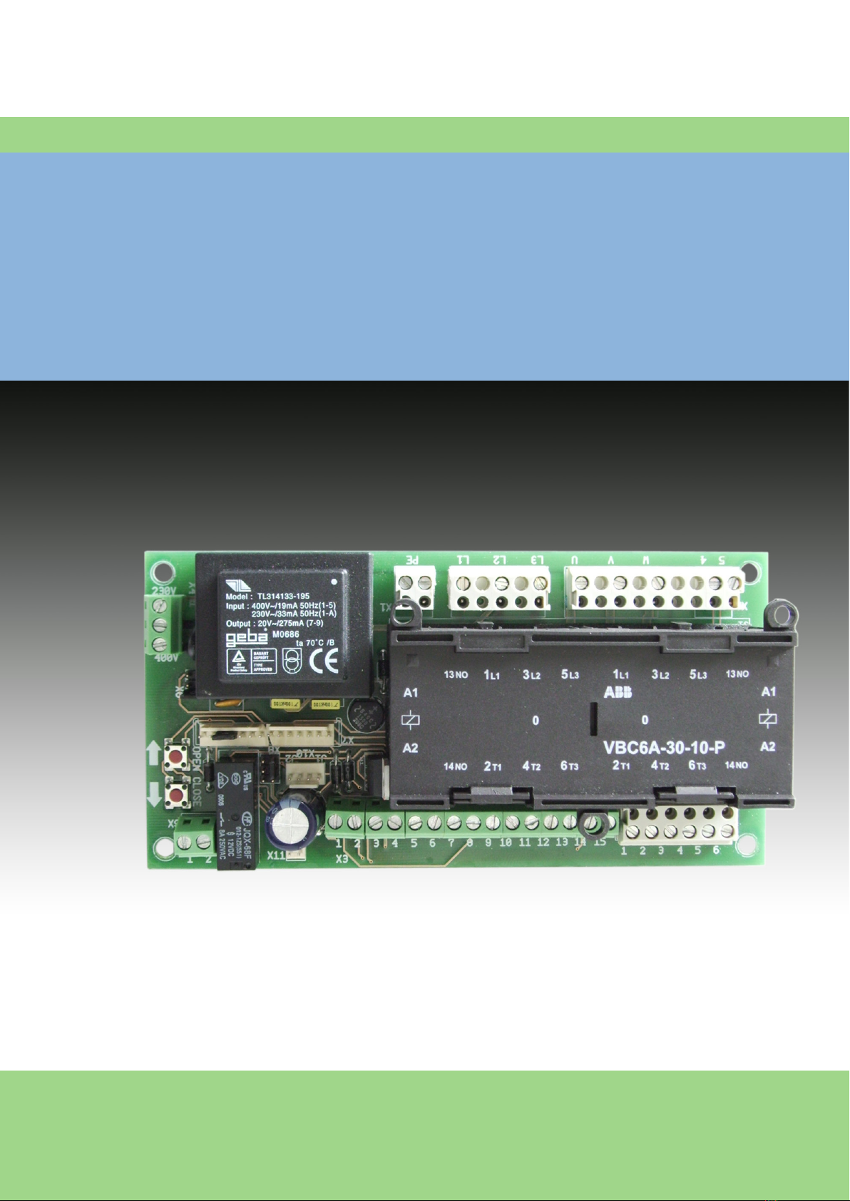
4.2 AS 210 B moederbord
12345678910 11 12 13 14 15 123456
123
PE L1 L2 L3 UVW45
X5
X3
X1 X2
X7
12
X9
AUF ZU
X4
X8
X6
J2 J1 X10
X11
J4 J5
J3
A
Verklaring:
A: Insteltoets OPEN (S01) /
Insteltoets DICHT (S02)
X1: Klemmenstrip netaansluiting
X2: Klemmenstrip motor / veiligheidsketting aandrving
X3: Klemmenstrip commandoapparaten
X4: Klemmenstrip netspanningsselectie
X5: Aansluitstrip eindschakelaar
X6: Aansluitstrip drievoudige toets
X7: Opsteeksokkel voor ZM SKS B printplaat
X8: Opsteeksokkel voor spiraalkabel
X9: Klemmenstrip verkeerslicht / erfverlichting
(alleen in combinatie met ZM SKS B steekkaart)
X10: Aansluitstrip zelfhoudend contact OPEN - DICHT
X11: Aansluitstrip remrelais
EMV
− EN 50014-1 (Emissienorm huishoudelke apparaten)
−EN 61000-3-2 (Limietwaarden voor de emissie van
harmonische stromen)
−EN 61000-3-3 (Limietwaarden voor spanningswisselingen,
spanningsschommelingen en ikkering in openbare laag-
spanningsnetten)
−EN 61000-6-2 (Elektromagnetische compatibiliteit (EMV) -
Deel 6-2: Algemene normen - Immuniteit voor industriële
omgevingen)
−EN 61000-6-3 (Elektromagnetische compatibiliteit (EMV)
- Deel 6-3: Algemene normen - Emissienormen voor
huishoudelke, handels- en lichtindustriële omgevingen)
Machinerichtlnen
−EN 60204-1 (Veiligheid van machines - Elektrische
uitrusting van machines; deel 1: Algemene eisen)
−EN 12100-1 (Veiligheid van machines - Basisbegrippen,
algemene ontwerpbeginselen -
Deel 1: Basisterminologie, methodologie)
Laagspanning
− EN 60335-1 (Huishoudelke en soortgelke
elektrische toestellen - Veiligheid)
− EN 60335-2-103 (Bzondere eisen voor poorten, deuren en
ramen)
Comité voor arbeidsplaatsen (ASTA)
−ASR A1.7 (Technische regels voor arbeidsplaatsen / Duitse
richtln voor aangedreven ramen, deuren en poorten)
4. Productoverzicht
NL
AS 210 B deurbesturing / Rev.A 2.0 – 5
5. Ingebruikname
5.1 Algemeen
Voor een onberispelke werking moet aan de volgende voor-
waarden zn voldaan:
−De deur is gemonteerd en klaar voor gebruik.
−De tandwielvertragingsmotor is gemonteerd en klaar voor
gebruik.
−De commando- en veiligheidsapparaten zijn gemonteerd en
klaar voor gebruik.
−De AS 210 B besturing is gemonteerd.
INFORMATIE
Volg de instructies van de betreffende fabrikanten op voor
de montage van de deur, de tandwielvertragingsmotor en de
commando- en veiligheidsapparaten.
5.2 Netaansluiting
Vereisten
Voor een onberispelk functioneren van de besturing moet
aan de volgende voorwaarden zn voldaan:
−De netspanning moet overeenkomen met de aanduiding op
het typeplaatje.
−Bij draaistroom moet er een rechtsdraaiend draaiveld zijn.
−Bij een vaste aansluiting moet een meerpolige
hoofdschakelaar worden toegepast.
−Bij draaistroomaansluiting mogen alleen
3-blokszekeringautomaten (10A) worden toegepast.
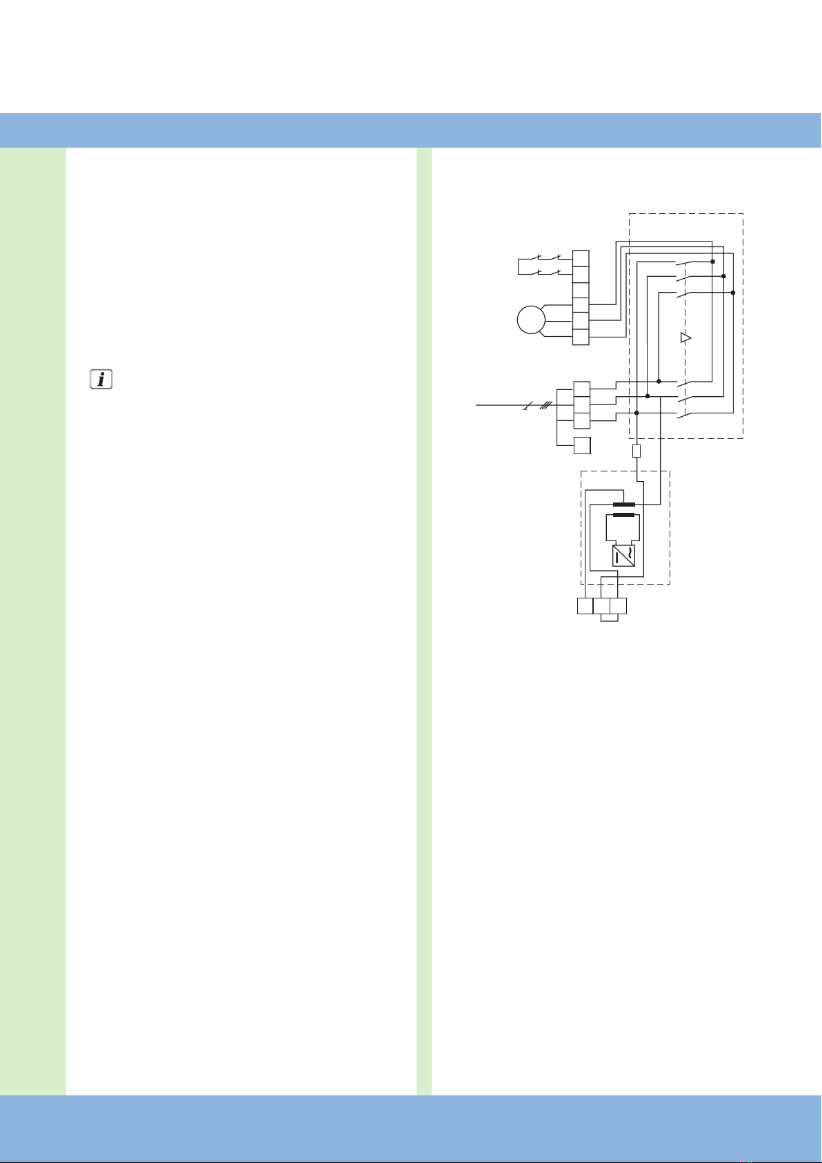
Gedetailleerd schakelschema en motor
400 V / 3-fasen
Verklaring:
F1 Thermische beveiliging besturingsspanning
F2 Thermische beveiliging motor
K1 Schakelaar OPEN
K2 Schakelaar DICHT
M Motor (400 V / 50 Hz / 3-fasen)
S3 Veiligheidseindschakelaar OPEN (opener)
S4 Veiligheidseindschakelaar DICHT (opener)
S7 Veiligheidseindschakelaar noodhandbediening
(opener)
T1 Transformator
X1 Klemmenstrip netaansluiting
X2 Klemmenstrip motor
X4: Klemmenstrip netspanningsselectie
54WVU L3 L2 L1 PE
12 3
400V
400 V / 50 Hz
6 – AS 210 B deurbesturing / Rev.A 2.0
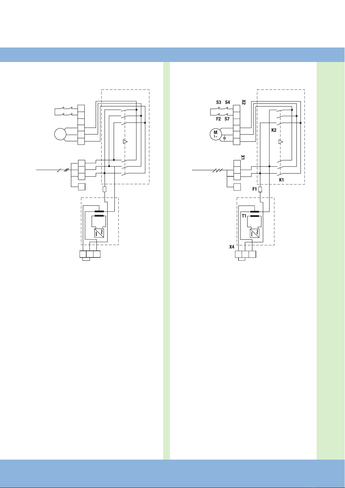
Gedetailleerd schakelschema en motor
230 V / 3-fasen
Verklaring:
F1 Thermische beveiliging besturingsspanning
F2 Thermische beveiliging motor
K1 Schakelaar OPEN
K2 Schakelaar DICHT
M Motor (230 V / 50 Hz / 3-fasen)
S3 Veiligheidseindschakelaar OPEN (opener)
S4 Veiligheidseindschakelaar DICHT (opener)
S7 Veiligheidseindschakelaar noodhandbediening (ope-
ner)
T1 Transformator
X1 Klemmenstrip netaansluiting
X2 Klemmenstrip motor
X4 Klemmenstrip netspanningsselectie
Gedetailleerd schakelschema en motor
230 V / 1-fasen
Verklaring:
F1 Thermische beveiliging besturingsspanning
F2 Thermische beveiliging motor
K1 Schakelaar OPEN
K2 Schakelaar DICHT
M Motor (230 V / 50 Hz)
S3 Veiligheidseindschakelaar OPEN (opener)
S4 Veiligheidseindschakelaar DICHT (opener)
S7 Veiligheidseindschakelaar noodhandbediening (ope-
ner)
T1 Transformator
X1 Klemmenstrip netaansluiting
X2 Klemmenstrip motor
X4 Klemmenstrip netspanningsselectie
Aansluiting:
Besturing op het elektriciteitsnet aansluiten.
Besturing op de motor aansluiten.
Kabelbundels moet direct voor de betreffende klem met een
kabelbinder worden vastgezet.
Ingebruikname
54WVU L3 L2 L1 PE
12 3
230V
230 V / 50 Hz
54NAUF ZU LN PE
12 3
230V
230 V / 50 Hz
NL
AS 210 B deurbesturing / Rev.A 2.0 – 7
5.4 Aansluitschema van commando- en
veiligheidsapparaten
Via de klemmen X3en X9 kunnen de aanwezige commando-
en veiligheidsapparaten worden aangesloten.
Klemmenstrip X3
- Knop STOP
- Knop OPEN
- Knop DICHT
- Onderlst (SKS)9
24 V DC max. 150 mA
- Impulsingang / afstandbediening9
- Fotocelbeveiliging inrit9
Klemmenstrip X9
- Potentiaalvre aansluiting voor
rood verkeerslicht of erfverlich-
ting9
9Alleen in combinatie met ZM SKS B steekkaart
1
2
3
4
5
6
7
8
9
10
11
12
13
14
15
1
2
5678
U
V
W
4
5
6
5
4
3
2
1
4
1
2
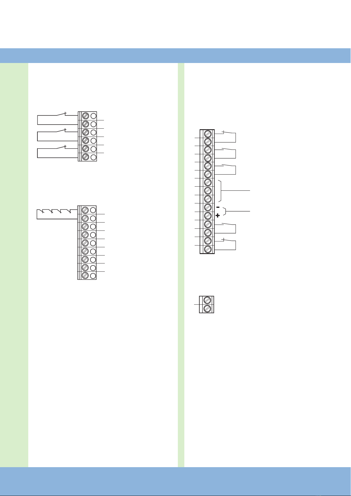
5.3 Aansluitschema eindschakelaar
(klem X5 en X2)
Klemmenstrip X5
Klemmenstrip X2
1Eindschakelaar OPEN
2Eindschakelaar DICHT
4Vooreindschakelaar DICHT
(Na activering wordt de deur niet omgekeerd)
5Thermische beveiliging motor
6Noodbediening (opener)
7Veiligheidseindschakelaar DICHT
8Veiligheidseindschakelaar OPEN

8 – AS 210 B deurbesturing / Rev.A 2.0
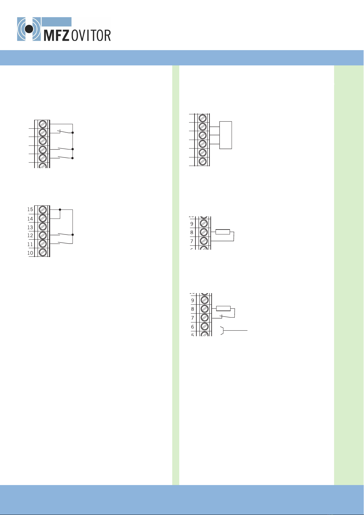
5.6 Aansluitvoorbeelden in combinatie met
de ZM SKS B steekkaart (klem X3)
Voor optisch-elektrische onderlst
- De dipschakelaar 1 moet op OFF staan.
Voor onderlst van 8,2 kOhm
- De dipschakelaar 1 moet op ON staan.
Voor pneumatische onderlst
- Een weerstand van 8,2 kOhm moet met de
DW- (drukgolf) schakelaar in serie worden geschakeld.
- De dipschakelaar 1 moet op ON staan.
- De dipschakelaar 2 moet op ON staan.
wt: wit
gr: groen
br: bruin
Ingebruikname
8,2
8,2
1
2
3
4
5
6
7
8
9
10
11
12
13
14
15
+12 V
Sig
GND
br
gr
wt
5.5 Aansluitvoorbeelden commando- en
veiligheidsapparaten (klem X3)
Knop OPEN / STOP / DICHT
(4-aderige oplossing)
- Knop STOP
- Knop OPEN
- Knop DICHT
Sleutelschakelaar OPEN / DICHT
- Knop OPEN
- Knop DICHT
1
2
3
4
5
6
7
8
9
10
11
12
13
14
15

NL
AS 210 B deurbesturing / Rev.A 2.0 – 9
Voor fotocellen met 3-dradentechniek
3Fotocel (NPN)
3
1
2
3
4
5
6
7
8
9
10
GND
+24V
5.7 Gedetailleerd aanzicht AS 210 B
X6 – opsteekstokkel voor 3-voudige knop
- wordt de opsteeksokkel niet
gebruikt, dan moet jumper 4
erop worden gestoken.
X8 - Opsteeksokkel voor spiraalkabel
- wordt de opsteeksokkel niet
gebruikt, dan moet jumper 3
erop worden gestoken.
X7 - Opsteeksokkel voor ZM SKS B printplaat
- wordt de opsteeksokkel niet
gebruikt, dan moet jumper 5
erop worden gestoken.
DICHT
OPEN STOP
J4
zwart /
geel
(STOP) wit (-)
J3
groen (Sig)
bruin (+12V)
J5
10 – AS 210 B deurbesturing / Rev.A 2.0
X10 - Aansluitstrip voor zelfhoudend contact
(OPEN + DICHT)
J1 (OPEN)
J2 (DICHT)
J1 en J2 moeten in combinatie met de ZM SKS B uitbreidings-
kaart open zn.
ATTENTIE!
Kans op functiestoring van de printplaat als gevolg
van verkeerde aansluiting!
Is J2 erop gestoken, dan volgt er geen stopcommando van
de onderlst in neerwaartse richting.
X11 - Aansluitstrip voor remrelais
ATTENTIE!
Kans op materiële schade van de printplaat door
verkeerde aansluiting!
Om schade aan de besturing te voorkomen, mag X11 in
geen geval van een jumper worden voorzien.
Op de aansluitstrip X11 kan er af fabriek een remrelais
worden aangesloten.
erop gestoken – zelfhoudend contact
niet erop gestoken = dodeman
Ingebruikname
Afmetingen
printplaat:
167 x 85 x 190 mm
Voeding via
L1, L2, L3, PE:
230 V of 400 V, 50 / 60 Hz;
Opnamevermogen max. 2200 W - 3,2 A;
inschakelduur 60% bij een duur van max. 120 s
Zekering: 10 A K-karakteristiek
Eigen gebruik van de
besturing:
Max. 100 mA
Stuurspanning: 24 V DC, max. 250 mA; beveiligd met een
zelfterugschakelende zekering voor externe
sensoren; alle besturingsspanningsingangen
zijn t4en opzichte van de voeding galvanisch
gescheiden
Besturingsingangen: 24 V DC, alle ingangen moeten potentiaalvrij
worden aangesloten. Min. signaalduur voor
ingangsbesturingscommando > 100 ms
Besturingsuitgangen: 24 V DC, max. 150 mA
Veiligheidscircuit /
noodstop:
Alle ingangen moeten per se potentiaalvrij
worden aangesloten; bij onderbreking van de
veiligheidscircuit is geen elektrische beweging
meer mogelijk, ook niet in de dodemansstand.
Ingang van de veilig-
heidslijst:*
Voor elektrische veiligheidslijsten met
8,2 kOhm, afsluitweerstand en voor dynamische
optische systemen
Relaisuitgangen:* Worden relaisuitgangen met inductieve
belastingen geschakeld (bijv. verdere relais of
remmen), dan moeten deze met de betreffende
ontstoringsmaatregelen (vrijloopdiode,
varistoren, weerstandcondensator) worden uit-
gerust. Werkcontact potentiaalvrij; min. 10 mA ;
max. 230 V AC / 4 A.
Eenmaal voor vermogensschakeling gebruikte
contacten kunnen geen zwakstroom meer
schakelen.
Temperatuurbereik: Gebruik: -10°C ... +45°C
Opslag: -25°C ... +70°C
Luchtvochtigheid: tot 80% niet condenserend
Gewicht: ca. 1,8 kg
Richtlijnen: Normen
* Alleen in combinatie met de ZM SKS B uitbreidingskaart
6. Technische gegevens

NL
AS 210 B deurbesturing / Rev.A 2.0 – 11
7. EG-inbouwverklaring
Hierb verklaren w dat de hieronder aangegeven product:
AS 210 B deurbesturing
aan de basiseisen van de machinerichtln (2006/42/EG)
voldoet:
De niet-voltooide machine voldoet verder aan alle bepalingen
van de
−EG-bouwproductenverordening (305/2011/EU)
−EG elektromagnetische compatibiliteitsrichtlijn
(2014/30/EU)
−EG-laagspanningsrichtlijn (2014/35/EU)
De volgende normen worden toegepast:
EN 60204-1
Veiligheid van machines, elektrische uitrusting van machines;
Deel 1: Algemene eisen
EN ISO 12100
Veiligheid van machines - Veiligheid van machines -
Basisbegrippen, algemene ontwerpbeginselen - Deel 1:
Basisterminologie, methodologie
DIN EN 12453
Gebruiksveiligheid van aangedreven deuren - Eisen
prEN 12453 : 2014
Veiligheid bij het gebruik van automatische deuren
(uitsluitend voor de punten 1.3.7 en 1.4.3 van bijlage I van de
Machinerichtlijn)
DIN EN 61000-6-2
Elektromagnetische compatibiliteit (EMV) -
Deel 6-2: Algemene normen – Immuniteit voor industriële
omgevingen
DIN EN 61000-6-3
Elektromagnetische compatibiliteit (EMV) -
Deel 6-3: Algemene normen – Emissienormen voor
huishoudelke, handels- en lichtindustriële omgevingen
DIN EN 60335-1
Huishoudelke en soortgelke elektrische toestellen -
Veiligheid - Deel 1: Algemene eisen
DIN EN 60335-2-103
Huishoudelke en soortgelke elektrische toestellen -
Veiligheid - Deel 2-103: Bzondere eisen voor poorten,
deuren en ramen
De relevante technische documentatie is in overeenstemming
met blage VII, deel B, van de EG-machinerichtln 2006/42/
EG opgesteld. W zetten ons in om deze op verzoek binnen
een redelke termn in elektronische vorm in te dienen b de
autoriteiten voor markttoezicht.
Voor de samenstelling van de technische documentatie is
gemachtigd:
De onvolledige machine mag pas in bedrf worden genomen
als is vastgesteld dat de machine, waarin de onvolledige
machine wordt ingebouwd, voldoet aan de bepalingen van de
machinerichtln (2006/42/EG).
Plaats, datum
Handtekening fabrikant
Functie van de ondertekenaar

#1700009779

EN
Operating Instructions for Door Controls AS 210 B
Door Control AS 210 B / Rev.A 2.0 – 1
2 – Door Control AS 210 B / Rev.A 2.0
1. Contents
1. Contents 2
2. Information in this document 2
3. General safety instructions 3
4. Overview of product 4
5. Initial operation 5
6. Technical data 10
7. EC Declaration of Incorporation 11
Original operating instructions
−Copyright.
−No part of these instructions may be reproduced without
our prior approval.
−Subject to alterations in the interest of technical progress.
−All dimensions given in mm.
−The diagrams in this manual are not to scale.
Key to symbols
DANGER!
Indicates a hazard with a high level of risk which, if not
avoided, will result in death or serious injury.
WARNING!
Indicates a hazard with a medium level of risk which, if not
avoided, could result in death or serious injury.
CAUTION!
Indicates a hazard with a low level of risk which, if not
avoided, could result in minor or moderate injury.
ATTENTION!
Indicates an imminent danger of damage or destruction.
CHECK
Indicates a check to be performed.
REFERENCE
Reference to separate documents which must be complied
with.
Action request
−List, itemisation
ÔReference to other sections of this document
2. Information in this document

EN
Door Control AS 210 B / Rev.A 2.0 – 3
3. General safety instructions
DANGER!
Failure to comply with the documentation could
result in life-threatening danger!
Be sure to follow all the safety instructions in this
document.
Warranty
The function and safety of the equipment is only guaranteed
if the warning and safety instructions included in these
operating instructions are adhered to.
MFZ Antriebe GmbH + Co. KG is not liable for personal
injury or damage to property if these occur as a result of the
warnings and safety advice being disregarded.
MFZ does not accept any liability or warranty for damage due
to the use of non-approved spare parts and accessories.
Using the equipment for its intended purpose
The AS 210 B controls are intended exclusively for controlling
door systems.
The controls may only be used in dry rooms.
Target group
Only qualied and trained electricians may connect,
programme and service the controls.
Qualied and trained electricians meet the following
requirements:
− have knowledge of the general and specic safety and
accident prevention regulations,
−have knowledge of the relevant electrical regulations,
−are trained in the use and care of appropriate safety
equipment,
−are capable of recognising the dangers associated with
electricity.
Instructions for installation and connection
−The controls must be disconnected from the electricity sup-
ply before carrying out electrical works. It must be ensured
that the electricity supply remains disconnected during the
works.
−Local protective regulations must be complied with.
−Mains cables and control cables must be laid separately.
− Consult the manufacturer before carrying out modications
or replacing the mains connection cable.
Information concerning operation
−Unauthorised persons (particularly children) should not be
allowed to play with permanently installed adjusting or
control devices.
−Keep remote controls beyond the reach of children.
Regulations and bases for testing
For connecting, programming and servicing, the following
regulations must be observed (the list is not exhaustive).
Construction product standards
− EN 13241-1 (Products without re resistance or smoke
control characteristics)
−EN 12445 (Safety in use of power operated doors -
Test methods)
−EN 12453 (Safety in use of power operated doors -
Requirements)
−EN 12978 (Safety devices for power operated doors and
gates - Requirements and test methods)
Electromagnetic compatibility
−EN 55014-1 (Radio disturbance, household appliances)
−EN 61000-3-2 (Disturbances in supply systems -
harmonic currents)
−EN 61000-3-3 (Disturbances in supply systems -
voltage uctuations)
−EN 61000-6-2 (Electromagnetic compatibility (EMC) -
Part 6-2: Generic standards - Immunity for industrial
environments)
−EN 61000-6-3 (Electromagnetic compatibility (EMC) -
Part 6-3: Generic standards - Emission standard for
residential, commercial and light-industrial environments)
Machinery guidelines
−EN 60204-1 (Safety of machinery, electrical equipment of
machines, part 1: general requirements)
−EN 12100-1 (Safety of machinery. Basic concepts, general
principles for design. Basic terminology, methodology)
4 – Door Control AS 210 B / Rev.A 2.0
Low voltage
−EN 60335-1 (Household and similar electrical appliances -
Safety)
−EN 60335-2-103 (Particular requirements for drives for
gates, doors and windows)
Committee for Workplaces (ASTA)
−Workplace regulation ASR A1.7 (“Doors and gates“)
4. Overview of productGeneral safety instructions
4.1 Functions
The basic model of the AS 210 B controls is designed only for
deadman operation.
The AS 210 B controls can be upgraded with the ZM SKS B
plug-in circuit card. With the help of this plug-in card, a clos-
ing edge safety device strip can be connected.
The following functions can then be set:
− red trafc light
−yard light
−automatic closing
−excess travel monitoring
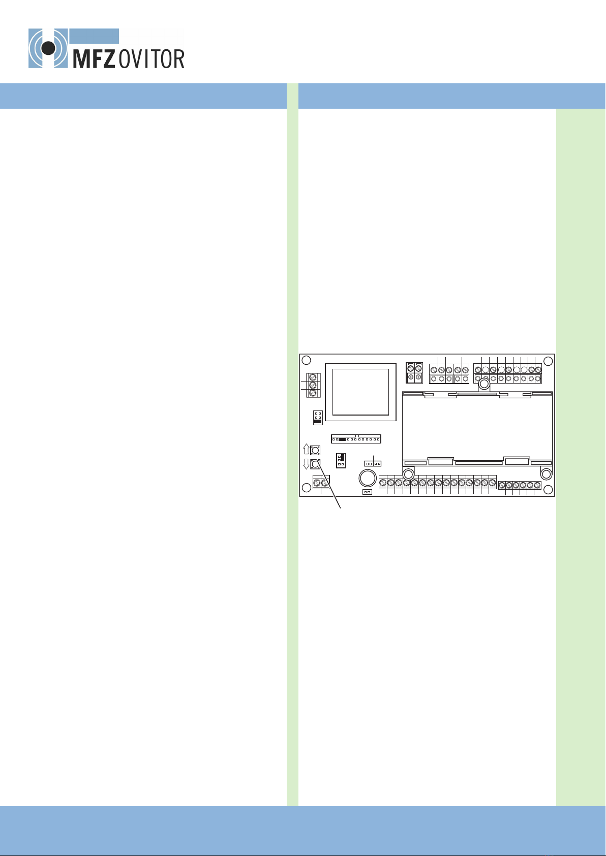
4.2 Motherboard, AS 210 B
12345678910 11 12 13 14 15 123456
123
PE L1 L2 L3 UVW45
X5
X3
X1 X2
X7
12
X9
AUF ZU
X4
X8
X6
J2 J1 X10
X11
J4 J5
J3
A
Description:
A: Setting button OPEN (S01) /
Setting button CLOSE (S02)
X1: Terminal block for mains connection
X2: Terminal block for motor / safety circuit for drive
X3: Terminal block for command devices
X4: Terminal block for mains voltage selection
X5: Terminal block for limit switches
X6: Terminal block for 3-way switch
X7: Plug-in base for ZM SKS B circuit card
X8: Plug-in base for spiral cable
X9: Terminal block for trafc light / yard light
(only in connection with a ZM SKS B plug-in circuit
card)
X10: Terminal block for press-and-release CLOSE- OPEN
X11: Terminal block for braking relay

EN
Door Control AS 210 B / Rev.A 2.0 – 5
5. Initial operation
5.1 General
To guarantee that the equipment functions properly, it must
be ensured that:
−the door is installed and operational.
−the MFZ drive motor is installed and ready for operation.
−the command and safety devices are installed and ready for
operation.
−the AS 210 B controls are installed.
REFERENCE
The relevant manufacturers’ instructions must be adhered to
for the installation of the door, the MFZ drive motor, and the
command and safety devices.
5.2 Mains connection
Preconditions
To guarantee that the controls function properly, the follow-
ing points must be ensured:
−The mains voltage must correspond to the voltage stated
on the type plate.
− For a three-phase current, a clockwise rotating eld is
required.
−For a permanent connection, an all-pole main switch must
be used.
−For a three-phase connection, only 3-way automatic circuit
breakers (10A) may be used.
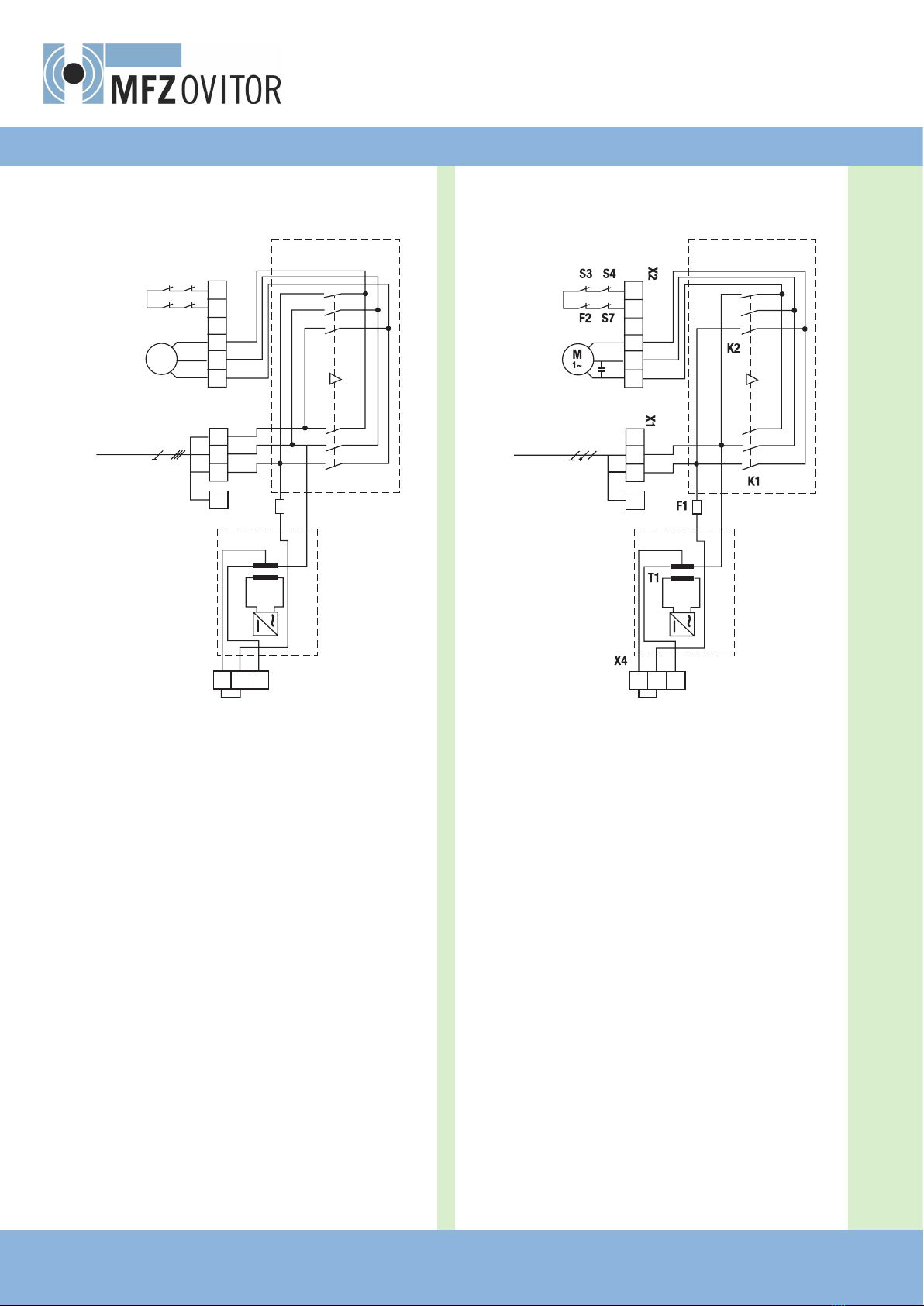
Detailed circuit diagram for mains connection and
motor 400 V / 3-phase
Description:
F1 Thermal fuse, control voltage
F2 Thermal overload protection for motor
K1 Protection OPEN
K2 Protection CLOSE
M Motor (400 V / 50 Hz / 3-phase)
S3 Safety limit switch OPEN
(normally closed contact)
S4 Safety limit switch CLOSE
(normally closed contact)
S7 Safety switch, emergency manual operation (normally
closed contact)
T1 Transformer
X1 Terminal block for mains connection
X2 Terminal block for motor
X4 Terminal block for mains voltage selection
54WVU L3 L2 L1 PE
12 3
400V
400 V / 50 Hz
6 – Door Control AS 210 B / Rev.A 2.0
Detailed circuit diagram for mains connection and
motor 230 V / 3-phase
Description:
F1 Thermal fuse, control voltage
F2 Thermal overload protection for motor
K1 Protection OPEN
K2 Protection CLOSE
M Motor (230 V / 50 Hz / 3-phase)
S3 Safety limit switch OPEN
(normally closed contact)
S4 Safety limit switch CLOSE
(normally closed contact)
S7 Safety switch, emergency manual operation (normally
closed contact)
T1 Transformer
X1 Terminal block for mains connection
X2 Terminal block for motor
X4 Terminal block for mains voltage selection
Detailed circuit diagram for mains connection and
motor 230 V / single phase
Description:
F1 Thermal fuse, control voltage
F2 Thermal overload protection for motor
K1 Protection OPEN
K2 Protection CLOSE
M Motor (230 V / 50 Hz)
S3 Safety limit switch OPEN (normally closed contact)
S4 Safety limit switch CLOSE (normally closed contact)
S7 Safety switch, emergency manual operation (normally
closed contact)
T1 Transformer
X1 Terminal block for mains connection
X2 Terminal block for motor
X4 Terminal block for mains voltage selection
Connection:
Connect the controls to the mains power supply.
Connect the controls to the motor.
Cable groups must be xed close to their relevant terminals
using a cable tie.
Initial operation
54WVU L3 L2 L1 PE
12 3
230V
230 V / 50 Hz
54NAUF ZU LN PE
12 3
230V
230 V / 50 Hz

EN
Door Control AS 210 B / Rev.A 2.0 – 7
5.4 Connection arrangement for command
and safety devices
Command and safety devices can be connected via terminals
X3 and X9.
Terminal block X3
- STOP button
- OPEN button
- CLOSE button
- Closing edge safety device (CES)9
24 V DC max. 150 mA
- Impulse input / radio9
- Photocell barrier9
Terminal block X9
- Potential-free connection for red
trafc light or yard light9
9Only in connection with an ZM SKS B plug-in circuit card
1
2
3
4
5
6
7
8
9
10
11
12
13
14
15
1
2
5678
U
V
W
4
5
6
5
4
3
2
1
4
1
2
5.3 Connection arrangement for limit
switches (terminals X5 and X2)
Terminal block X5
Terminal block X2
1 Limit switch OPEN
2Limit switch CLOSE
4Pre-limit switch CLOSE (after activation the door does not
reverse)
5Thermal overload protection for motor
6Emergency operation (normally closed contact)
7Safety limit switch CLOSE
8Safety limit switch OPEN
8 – Door Control AS 210 B / Rev.A 2.0
5.6 Connection examples in connection with
the ZM-SKS B plug-in module (terminal X3)
For optoelectric closing edge safety device
- DIP switch 1 must be set to the OFF position.
For 8.2 kOhm closing edge safety device
- DIP switch 1 must be set to the ON position.
For pneumatic closing edge safety device
- An 8.2 kOhm resistance must be connected in series with
the pressure switch.
- DIP switch 1 must be set to the ON position.
- DIP switch 2 must be set to the ON position.
wt: white
gr: green
br: brown
Initial operation
8,2
8,2
1
2
3
4
5
6
7
8
9
10
11
12
13
14
15
+12 V
Sig
GND
br
gr
wt
5.5 Connection examples for command and
safety devices (terminal block X3)
OPEN / STOP / CLOSE buttons
(4-lead solution)
- STOP button
- OPEN button
- CLOSE button
Key switch OPEN / CLOSE
- OPEN button
- CLOSE button
1
2
3
4
5
6
7
8
9
10
11
12
13
14
15
Table of contents
Languages:
Other MFZ Ovitor Gate Opener manuals


