Westfalia 18 39 13 User manual

Swing Gate Opener
Artikel Nr. 18 39 13
Instruction Manual

II
Please familiarize yourself with the proper usage of the device by reading and
following each chapter of this manual, in the order presented. Keep these
operating instructions for further reference.
This operating instruction contains important details for handling the device.
Please pass it on along with the unit if it is handed over to a third party!
Please read all safety instructions!
These instructions will make it easier for you to handle the device and help
prevent misunderstandings and possible damage or injury.
Dear Customers

III
Overview
1
4
2
5
6
7
8
9
10
12
14
16
18
20
19
17
15
13
11
3
Moving Gate
Can cause Injury or Death!
1. Keep Gate clear! Gate may move at any time.
2. Do not allow children to operate the gate or
play in the gate area.
3. The gate area is for vehicles only.
4. Read and understand the manual.
5. Pedestrians have to use a separate entry.
Do not remove this warning sign!
WARNING
Opener 1
Opener 2

IV
Overview
Pos.
Description
Pieces
1
Gate Opener
2 Pieces
2
Control Box
1 Piece
3
Triangular Key
2 Pieces
4
Warning Sign
2 Pieces in German
2 Pieces in English
5
Remote Control
2 Pieces
6
Post Bracket
4 Pieces
7
Post Pivot Bracket
2 Pieces
8
Gate Bracket
2 Pieces
9
Washer Ø M10 mm
14 Pieces
10
Hex Bolt M10 x 200 mm
8 Pieces
11
Lock Washer Ø M10 mm
14 Pieces
12
Hex Bolt M10 x 75 mm
4 Pieces
13
Washer Ø M8 mm
2 Pieces
14
Hex Bolt M10 x 30 mm
2 Pieces
15
Hex Nut M10 mm
14 Pieces
16
Hex Bolt M8 x 30 mm
2 Pieces
17
Hex Nut M8 mm
2 Pieces
18
Clevis Pin Ø 12 x 40 mm
2 Pieces
19
Hairpin Clip
4 Pieces
20
Clevis Pin Ø 12 x 30 mm
2 Pieces

1
Table of Contents
Safety Notes................................................................................................ Page 2
Preparation.................................................................................................. Page 4
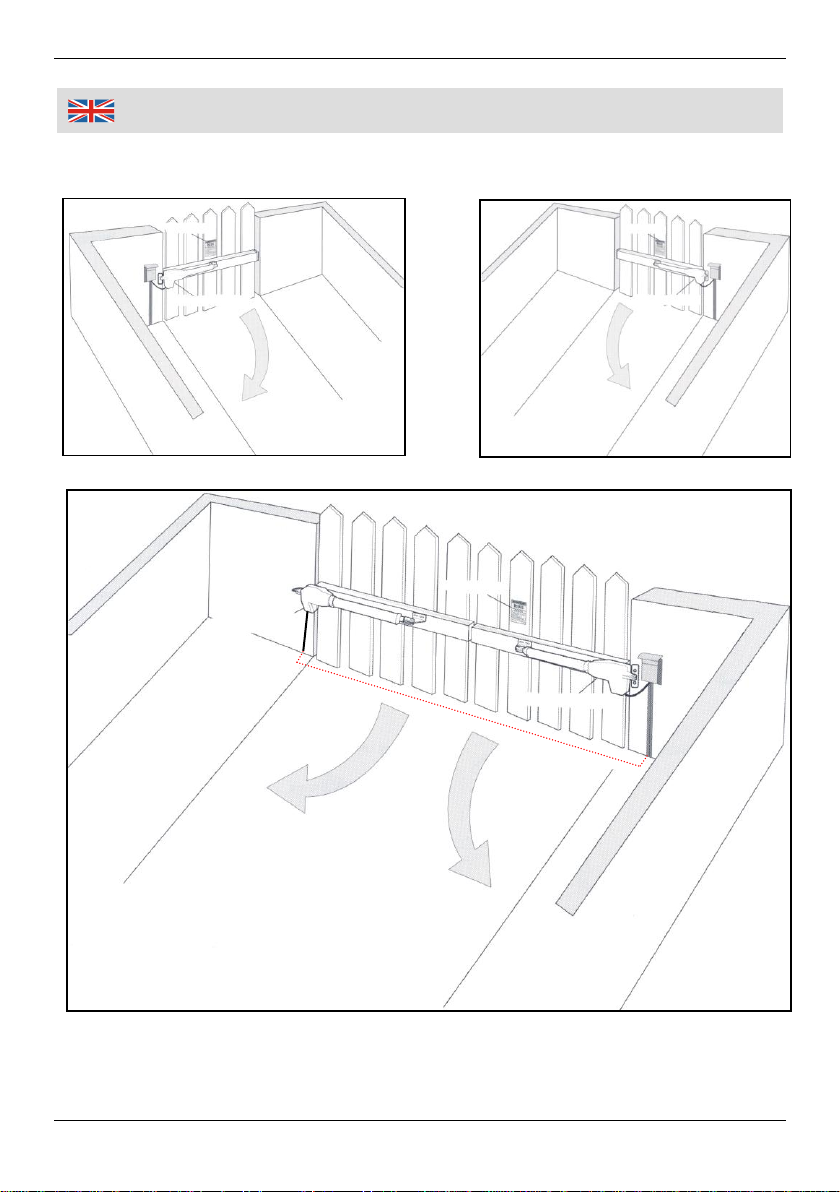
Mounting Possibilities ................................................................................. Page 5
Hints............................................................................................................ Page 6
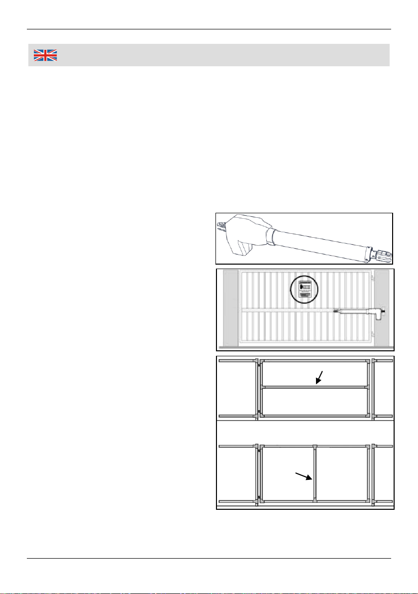
Types of Posts ............................................................................................ Page 7
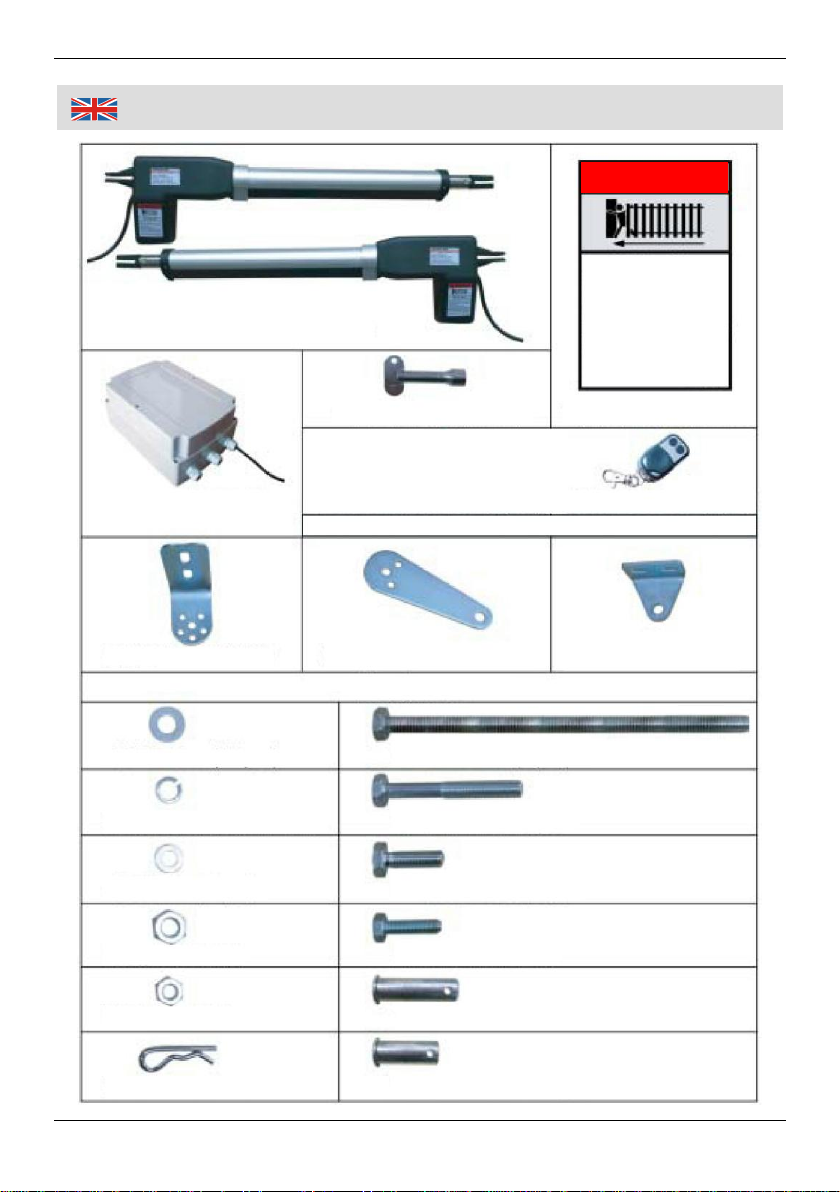
Assembly..................................................................................................... Page 8
Position of the Gate Opener ....................................................................... Page 9
Reference Table ......................................................................................... Page 10
Mounting ..................................................................................................... Page 11
Mounting and connecting the Control Box.................................................. Page 16
Wiring Diagram ........................................................................................... Page 17
Circuit Diagram ........................................................................................... Page 18
Programming one Gate Opener ................................................................. Page 19
Programming both Gate Openers............................................................... Page 20
P2 Setting Master/Slave Gate..................................................................... Page 20
P3 Setting the Master/Slave Open Interval................................................. Page 20
P4 Setting the Master/Slave Close Interval ................................................ Page 21
P5 Adjusting the Blocking Force for Gate Opener 1................................... Page 21
P6 Adjusting the Blocking Force for Gate Opener 2................................... Page 22
P7 Closing Time for Gate Opener 1 ........................................................... Page 22
P8 Closing Time for Gate Opener 2 ........................................................... Page 22
P9 Photocell Beam System ........................................................................ Page 22
PA Automatic Closing Time........................................................................ Page 23
Pb Soft Start................................................................................................ Page 23
PC Setting the Soft Start, Fast Running and Soft Stop Period................... Page 23
Pd Return to Factory Settings .................................................................... Page 25
Programming the Remote Control.............................................................. Page 26
Erase all Remote Control Codes ................................................................ Page 26
Using........................................................................................................... Page 27
Adjusting the Limit Switch........................................................................... Page 27
EMERGENCY Release............................................................................... Page 28
Using the Remote Control from the Car ..................................................... Page 28
Changing the Battery in the Remote Control.............................................. Page 29
Checking the Reversion.............................................................................. Page 29
Maintenance and Cleaning......................................................................... Page 29
Technical Data............................................................................................ Page 30
Connection Diagram for Accessory ............................................................ Page 31

Safety Notes
2
Make sure the voltage corresponds to the type label on the unit.
Persons with limited physical, sensorial or mental abilities are not allowed to
use the unit, unless they are supervised and briefed for their safety by a
qualified person.
The swing gate opener is designed for opening and closing light-weighted
swing gates. The swing gate opener is designed for private use only.
The swing gate opener is designed for operating swing gates in vehicle
drives. Pedestrians must use a separate entrance.
Basic knowledge in mechanics and electrics is required for properly installing
the swing gate opener. Incorrect mounting can cause serious injuries and
substantial property damages. Observe the local safety regulations to prevent
accidents. Westfalia assumes no liability for improper installation of the swing
gate opener.
Do not modify the swing gate opener in any way.
Electrical installation has to be carried out by a qualified professional only.
Check the whole swing gate system (joints mounting material etc.) for any
signs of wear or damages and do not use the swing gate opener with a
damaged swing gate system. Do not use the swing gate opener unless repair
work or alignment is carried out properly.
Disable the existing swing gate locks in order to avoid damages.
Ensure proper mounting when installing the swing gate opener. Check the
swing gate for proper mechanical operation. It is essential that the swing gate
can be easily opened and closed by hand.
The max. allowable gate size and gate weight must not be exceeded. Using
the gate opener on larger and heavier gate is not permitted.
Mount the control box within the sight of the gate. Mount the control box out of
the pivoting swing range of the gate, preferably in a height of 1.5 m from the
ground and out of reach of children. Do not allow children to play with the
control box or the remote control.
Attach the warning signs well visible on the gate and inform all user of the
swing gate opener about the risk during operation.
Only operate the gate opener if the gate is fully visible and there are no
obstructions, persons or animals. Keep persons or animals out of reach of the
gate as long as the gate is not completely opened or closed.
Please note the included General Safety Notes and the following
safety notes to avoid malfunctions, damage or physical injury:

Safety Notes
3
Please mind the danger area. There is risk of pinching. Please observe the
drawings on page 13.
Do not allow children to stand or play in the gate area.
Wait until the gate has come to a complete standstill before driving in or out.
Do not pinch the power cord in any way while connecting with the control box.
Hints for persons with cardiac pacemaker. The transmission range of the
remote control is within the relevant standards and generally harmless. To
eliminate residual risk we recommend not carrying the remote control directly
on your body. For your safety, when using the remote control keep it away
from your body and in direction to the gate.
Before undertaking any maintenance on the swing gate opener, unplug from
power mains (except of test run and while programming).
Do not grasp moving parts while the swing gate opener is in operation. There
is risk of pinching!
Keep the swing gate bottom and the ground clean and free of snow, ice,
stones etc.
Only use original spare parts, original accessory and mounting material.
Should the swing gate opener becomes damaged, do not use it any further
and have it repaired by a professional or send it back to our customer support
department. Do not disassemble the unit and do not try to repair it yourself.

Preparation
4
Before first Use
Unpack all parts of the swing gate opener set and check for any damage in transit
resp. for completeness. Compare the scope of delivery with the pages III + IV.
Dispose of packaging materials or store it out of reach of children. Plastic bags
etc. may become a deadly toy for children.
Mounting Conditions/Requirements
The swing gate opener is designed for light-weighted swing gate systems in
private use only.
The swing gate opener is designed for gates with max. weight of 300 kg and
with a length of max. 3 m and a max. height of 3 m. The structure of the gate
has to be rigid (Iron, Metal, Wood).
The swing gate system must be in good mechanical and trouble-free
condition and should not be damaged or has signs of wear. It must be
possible to open and close the gate by hand without any problems. The
mechanical gate lock must be dismounted resp. disengaged.
The control box may only be installed by a qualified professional in an easily
accessible place.
Preparation
1. To ensure proper and quick mounting, read the manual thoroughly.
2. Allow a second person to assist you. This will make installation easier.
3. Have the required tools available.
- Power Drill and Drill Bits - Tape Measure/Folding Ruler
- Open End Wrenches (Size 14 and 17) - Wire Stripers
- Small Level - Hacksaw
- Philips and Slot Screwdriver - Ball Pen/Pencil
4. Disengage the existing swing gate lock.
Hint: The swing gate does not need an additional lock as the swing gate
opener is self-locking when connecting to the control box. The gate cannot be
easily opened without damaging the gate opener or the hinges of the gate
system.

Mounting Possibilities
5
Warnschild
Warning Sign
Opener 2
Property
(2)
Property
(2)
Opener 1
Warning Sign
Warning Sign
Opener 2
Opener 1
Property
(2)

Hints
6
Power cable (red doted line shown in the picture on page 5) must be put into
a PVC conduit and placed underground in order to avoid damaging the
cables. If digging is not possible, put the power cable into a PVC conduit that
is stable enough to withstand vehicles passing over.
The swing gate opener is operated with 230 V~ 50 Hz. The electrical wiring
should be exclusively for the gate opener and it should be additionally
protected by a 10 A fuse.
Power supply should be connected with an EMERGENCY-STOP-Main
Switch. In case of questions, contact a professional.
For correctly programming the gate openers, it is essential that gate opener 1
is mounted at the right side of the gate and gate opener 2 is mounted at the
left side of the opener (view from
inside of the property).
The gate opener must be mounted
that way, so the motor is facing
downwards.
One or both gate openers can be
either mounted at the middle of the
gate (this will be the best static
position) or at the bottom of the gate
(for a uniform appearance).
If the gate system does not have
vertical braces or a horizontal cross
member, then the gate system has
to be reinforced prior to mounting
the gate opener.
Cross Member
Vertical Brace

Types of Posts
7
Timber
Metal Plate
Metal Plate
Timber
(6)
(7)
(6)
(7)
Concrete
(6)
(7)
4 Dowels
Ø 10 mm
The mounting material can be mounted on wooden posts, on square concrete
posts or concrete walls.
If the post diameter is smaller than 15 cm, make sure the post is set in
cement in order to ensure stability.
When mounting on stone or concrete posts, use dowels that cannot slacken.
Preferably use compound anchors (better than standard steel and PVC
expansion dowels).
When mounting on brick walls preferably fix a large steel plate on the wall and
make sure the plate covers several brick lines.
For mounting the post brackets (6) you can also use an angle plate. This
angle plate can be fixed around the post edge.

Assembly
8
(8)
(18)
Front Mount
(19)
(20)
Bracket Assy
Rear Mount
(19)
1. Assemble the post bracket (6) together with
the post pivot bracket (7), as shown in the
drawing.
2. Tighten the hex nut but do not overtighten.
3. Mount the gate opener 1 with the already
assembled bracket assy (post pivot bracket
and post bracket) and use the clevis pin (20)
and the hairpin clip (19) in order to lock the
opener. Make sure the gate opener is mount-
ed with the motor facing downwards.
4. Mount the gate bracket
(8) on the front mount
of the gate opener (1).
Use the clevis pin (18)
and secure with the
hairpin clip (19).
(14)
(6)
(7)
(6)
(9)
(11)
(15)

Position of the Gate Opener
9
Moving Rod is extended
Post
(6)
(7)
(6)
(7)
Post
The instructions in this manual are intended for Pull-to-Open gate installation.
That means the gate will be opened by retracting the gate opener rod. Therefore
the gate opener must be installed from inside of the property. Make sure the gate
does not extend over public footpaths or roads while operating.
Please mind the table on the next page in order to determine the correct position
of the mounting material resp. the gate opener.
The distances A + B must not exceed 42 cm. The distance A must be at least 8
cm or longer. Example: If distance A is 20 cm, the distance B may not exceed 22
cm. The resultant angle may not be smaller than 90°.
The red marked angle setting should be avoided.
Make sure that the flat side
of the gate opener (red
arrows) is situated at the
gate side. This will ensure
a wider opening angle.

Reference Table
10

Mounting
11
Total length of the gate opener with extended moving rod: 120 cm
Total length of the gate opener with retracted moving rod: 81 cm
1. Insert the triangular key (3) into the housing and lightly press down while
turning the key counter clockwise. By doing this the gate opener will be
unlocked. Now the moving rod can be extended.
The moving rod should always be lubricated sufficiently. Make sure the
moving rod does not become dirty or dusty.
Determine the distances A + B.
2. Adjust the moving rod and insert the triangular into the housing. Turn the key
clockwise in order to lock the rod in place.

Mounting
12
(3)
Bracket Assy
Post
Opener
(8)
Opener is in OPEN Position
3. Mount the gate opener on a trail basis on the gate and fasten with clamps in
order to check correct position.
Make sure the gate opener is level!
Determine the correct position of the gate opener and the bracket assy. Please
also observe the drawings on the next page.
Make sure the min. distance between gate and gate opener is 2.5 cm. This
distance must be maintained in the gate-closed position and the gate-opened
position.
Make sure the gate opener and the bracket do not
hit each other. If the angle is not correct, readjust
the angle with the 5 openings in the post bracket.
16
14
13
4
17

Mounting
13
Min. 2.5 cm
Min. 2.5 cm
Gate is in CLOSED Position (Moving Rod is extended)
Danger Area (Pinch Area)
Make sure the gate opener and the
bracket do not hit each other.
Danger Area
(Pinch Area)
Gate is in OPEN Position (Moving Rod is retracted)

Mounting
14
1. Mark the drilling holes through the
bracket assy and drill holes with 10 mm
diameter into the gate post.
2. Mark the drilling holes through the gate
bracket and drill holes with 10 mm
diameter into the gate.
3. Tighten all screws and nuts. Protruding
bolt ends (10) should be cut with the
hacksaw.
Cover the gate opener while drilling. Please note that dust and swarf might
damage the gate opener.
Use the included screws or other suitable screws and dowels for the resp.
surface.
Drill Holes
Bracket Assy
Gate is in OPEN Position
10 mm Holes

Mounting
15
(8)
(19)
Post
Opener
Bracket Assy
(19)
Gate in OPEN Position
Braces
Wood/
Metal
Braces
Sturdy Metal Tube
8
If the braces of the gate are thin, the braces can be reinforced with sturdy metal
tubes. By doing this, the gate bracket (8) can be mounted securely on the braces.
A wooden or metal plate can also be screwed on the gate.
Now securely tighten all bolts and nuts. The assembly is finished.

Mounting and connecting the Control Box
16
1. Mount the control box (2) with suitable
screws and dowels for the resp. surface.
Preferably mount the control box approx.
150 cm above the ground. Make sure
the control box is not exposed to direct
sunlight, rain, snow or direct water jet
(high pressure water jet etc.).
2. Unscrew the lock nuts of the strain
relief and insert the power cable of the
gate opener from below into the control
box. Pull enough cable and tighten the
lock nuts of the strain relief.
The cables are labelled with small flags.
Please observe the flags and arrange
them correctly.
Order of the cables for Gate Opener 1:
Red cable to +Motor1
Black cable to –Motor1
Red cable to ULT1
Black cable to COM
Yellow cable to DLT1.
Order of the cables for Gate Opener 2:
Red cable to +Motor2
Black cable to –Motor2
Red cable to ULT2
Black cable to COM
Yellow cable to DLT2.
Please also observe the wiring diagram on
the next page.
Screws and
dowels
(not
included)
Opener 1
Opener 2
Table of contents
Other Westfalia Gate Opener manuals
Popular Gate Opener manuals by other brands

Eagle
Eagle Power II installation manual

CAME
CAME Ati-S3 Quick setup guide

Shark
Shark 500KG Manual for installation and operation

Pujol
Pujol Radius Installation and adjustment instructions

Platinum Access Systems
Platinum Access Systems BLSW2212-B Installation instructions & owner's manual

DoorKing
DoorKing 6002 Owners and wiring manual