MFZ Ovitor CS 300 RM User manual

Operating Instructions for CS 300 RM Controls EN
CS 300 RM Gate Controls Rev. B 1.0 – 1
2 – CS 300 RM Gate Controls / Rev. B 1.0
1. Contents 3. General safety instructions
2. Key to symbols
Original operating instructions
−Protected by copyright.
−No part of this manual may be reproduced without our
prior approval.
−Subject to alterations in the interest of technical progress.
−All dimensions are given in millimetres.
−The diagrams in this manual are not to scale.
Guarantee
The function and safety of the equipment is only guaranteed
if the warning and safety instructions included in these opera-
ting instructions are adhered to.
MFZ Antriebe GmbH + Co. KG is not liable for personal injury
or damage to property if these occur as a result of the war-
nings and safety advice being disregarded.
Using the equipment for its intended purpose
The CS 300 RM control unit is intended exclusively for the
purpose of controlling tubular drives that have mechanical
limit switch systems.
Target group
Only qualied and properly trained electricians are allowed to
connect up, programme or service the control unit.
Qualied and trained electricians must have the following:
− Knowledge of the general and specic safety and accident-
prevention regulations
−Knowledge of the relevant electrical regulations
−Training in the use and care of appropriate safety equip-
ment
−The ability to recognise the risks associated with electricity
Instructions relating to installation and connection
−Before commencing electrical works, the system must be
disconnected from the power supply. Measures must be
taken to ensure that the power supply remains switched off
for the duration of the works.
−The local safety regulations must be observed.
−Power cables must be laid separately from control cables.
Danger of personal injury!
The safety instructions must be observed!
Warning! Danger to property!
The safety instructions must be observed!
Information
Special information
OR
Reference to other sources of information
1. Contents 2
2. Key to symbols 2
3. General safety instructions 2
4. Overview of products 3
5. Initial operation 5
6. Programming with the LED module 10
7. Programming with the LCD monitor 12
8. Navigator (LCD monitor only) 14
9. Overview of functions 16
10. Error messages and rectication 23
11. Technical data 24
12. EC Declaration of Incorporation 25
13. Appendix 26

EN
CS 300 RM Gate Controls / Rev. B 1.0 – 3
Regulations and test specications
The following regulations must be complied with when
connecting, programming or servicing the unit. (The list is not
exhaustive.)
Construction product standards
− EN 13241-1 (Products without re resistance or smoke
control characteristics)
−EN 12445 (Safety in use of power operated doors -
Test methods)
−EN 12453 (Safety in use of power operated doors -
Requirements)
−EN 12978 (Safety devices for power operated doors and
doors - Requirements and test methods)
EMC
−EN 55014-1 (Electromagnetic compatibility - Requirements
for household appliances)
−EN 61000-3-2 (Limits for harmonic current emissions )
− EN 61000-3-3 (Limitation of voltage changes, voltage uc-
tuations and icker in public low-voltage supply systems)
−EN 61000-6-2 (Electromagnetic compatibility (EMC) - Part
6-2: Generic standards - Immunity for industrial environ-
ments)
−EN 61000-6-3 (Electromagnetic compatibility (EMC) - Part
6-3: Generic standards - Emission standard for residential,
commercial and light-industrial environments)
Machinery Directive
−EN 60204-1 (Safety of machinery, electrical equipment of
machines, Part 1: General requirements)
−EN 12100-1 (Safety of machinery - Basic concepts, general
principles for design, Part 1: Basic terminology, methodo-
logy)
Low voltage
−EN 60335-1 (Household and similar electrical appliances -
Safety)
−EN 60335-2-103 (Particular requirements for drives for
gates, doors and windows)
Committee for Workplaces (Ausschuss für Arbeitsstätten -
ASTA)
−ASR A1.7 (Technical Regulations for workplaces - Doors
and gates)
4.1 Various options
The following package options are available for the CS 300
RM controls:
−CS 300 RM control unit with LCD monitor
−CS 300 RM control unit with LCD monitor in housing
−CS 300 RM control unit with LED module for setting the
OPEN and CLOSED door positions (no further settings are
possible).
−CS 300 RM control unit without LED module and without
LCD monitor (a module or monitor is required for adjusting
the settings)
All the above options can be tted with a plug-in weekly
timer (switch clock) and a plug-in radio receiver.
The following options are available for the housing:
−Housing unit with 3-button input unit CS
−Housing unit with 3-button input unit KDT
−Housing with ON/OFF key switch
−Housing with mains switch
−Housing with emergency off button
The operating instructions describe the connection options
and programming procedures for the following models:
−CS 300 RM control unit with LED board
−CS 300 RM control unit with attached LCD display board
4. Overview of products
4 – CS 300 RM Gate Controls / Rev. B 1.0
4. Overview of products
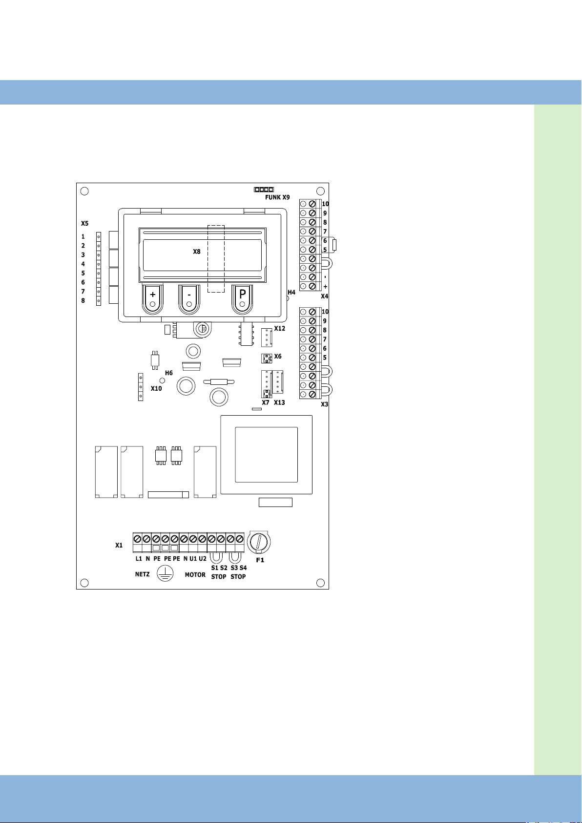
4.2 CS 300 RM main board
(with attached LCD display monitor)
Key:
X1: terminal block for mains
connection / motor
X3: terminal block for command
devices
X4: terminal block
safety devices / before-end
switch
X5: terminal block
relay
X6: terminals for internal ON-
OFF switch
X7: terminals for internal 3-but-
ton input unit
X8: socket for monitor
(under monitor)
X9: terminals for
radio receiver
X10: terminals for weekly timer
(switch clock)
X12: socket for external radio
receiver
X13: terminals for
CS 3-button input unit
H4: status display for safety edge
protection (SKS) – illumina-
ted when SKS is working
H6: Safety circuit status message
– lights up when the safety
circuit is closed
F1: 4A fuse

EN
CS 300 RM Gate Controls / Rev. B 1.0 – 5
5. Initial operation
5.1 General
Warning!
To guarantee that the equipment functions
properly, the following points must be
ensured:
The door is installed and operational.
- The MFZ tubular drive is installed and ready
for operation.
- The command and safety devices are instal-
led and ready for operation.
- The control housing with the CS 300 RM
control unit is installed.
Information:
For the installation of the gate/door, the MFZ
geared motor and the command and safety
devices, the relevant manufacturer’s instruc-
tions are to be adhered to.
5.2 Mains connection
Danger!
To ensure that the control unit functions pro-
perly, the following conditions must apply:
- The supply voltage must correspond to the
voltage shown on the type plate.
- The supply voltage must correspond to the
voltage of the door operator.
- If a permanent connection is to be made, an
all-pole mains switch must be installed.
Warning!
Before switching on the control unit for the
rst time, check to ensure that the cabling
works are complete and that all the motor
connections are secure at both the motor and
the control unit. All control voltage inputs are
separated galvanically from the mains power
supply.
6 – CS 300 RM Gate Controls / Rev. B 1.0
5. Initial operation
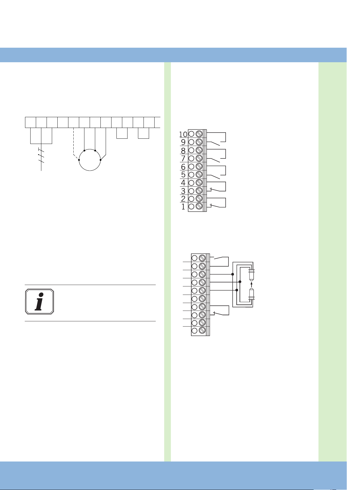
5.3 Assignment of connections for the motor
and the power supply
(terminal X1)
Terminal block X1
L1 N PE PE PE N U1 U2 S1 S2 S3 S4
M
230V / 1PH
230V / 1PH
S1-S4
Connection of mains switch (optional)
Connection:
Connect the control unit to the mains.
Connect the control unit to the motor.
Cable groups must be secured in place with a cable tie close
to their terminals.
Information:
Technical data, see page 24.
5.4 Assignment of connections for command
and safety devices
Command and safety devices can be connected to terminals
X3, X4 and X5.
Terminal block X3
- CLOSE button
- impulse button 1
- OPEN button
- STOP button
- Emergency off, slack rope switch,
wicket door contact, draw-in
protection
Terminal block X4
(for optoelectronic safety edge protection)
Part OPEN2
- safety edge protection
OPTO
- drive-through light
barrier3
- 24 V DC / 250 mA4
1 sequence control
2 button or selector switch
3 effective in down direction
4
for external switching devices (connection to terminals 1
and 2)
wt: white
gr: green
br: brown
1
2
3
4
5
6
7
8
9
10
+
-
wt
gr
br
EN
CS 300 RM Gate Controls / Rev. B 1.0 – 7
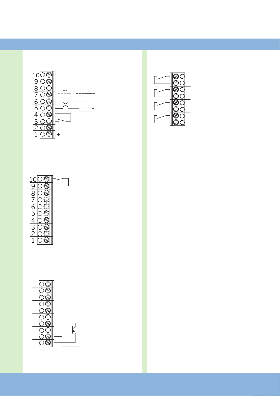
Terminal block X4
(for 8.2 kOhm safety edge protection)
- safety edge protec-
tion
- drive-through light
barrier -3
- 24 V DC / 250 mA4
Klemmleiste X4
(mit Vorendschalter für Reversierabschaltung)
- before-end switch
NO
Terminal block X4
(for 3-wire light barrier)
- 3-wire light barrier
Terminal block X5
(potential-free switch contacts)
- relay 1
- relay 2
- relay 3
- relay 4
8k2
1
2
3
4
5
6
7
8
9
10
24V
GND
1
2
3
4
5
6
7
8

8 – CS 300 RM Gate Controls / Rev. B 1.0
5. Initial operation
Key switch OPEN / CLOSE
- CLOSE
- OPEN
Impulse button
(sequence control)
- impulse button
Connection:
Connect any installed command and safety devices to the
control unit.
5.5 Connection examples for command and
safety devices (terminal X3)
OPEN / STOP / CLOSE buttons
(6-lead solution)
- CLOSE button
- OPEN button
- STOP button
OPEN / STOP / CLOSE buttons
(4-lead solution)
- CLOSE button
- OPEN button
- STOP button

EN
CS 300 RM Gate Controls / Rev. B 1.0 – 9

10 – CS 300 RM Gate Controls / Rev. B 1.0
6.1 Overview of the LED module
Key:
LED off
LED illuminated
LED ashing
6. Programming with the LED module
6.2 Operating modes of the LED module
With the LED module, the control unit has two modes of operation:
1. AUTOMATIC
2. ADJUSTMENT
Information:
The current mode of operation of the control unit is shown via the LEDs.
- In AUTOMATIC mode, no LEDs ash. The (+) and (-) buttons have no function.
- In the ADJUSTMENT mode, at least one LED ashes. The external buttons have no function.
Pressing the (P) button toggles between the modes of operation.
Operating mode 1: AUTOMATIC
In the AUTOMATIC operating mode the door system is operated automatically.
LED displays:
H1 H2 Status
The door is open. The OPEN limit switch has been reached.
The door is closed. The CLOSED limit switch has been reached.
The door is between end positions. No limit switch has been reached.
The OPEN and CLOSE limit switches have been interrupted
(illogical state = TERM SWITCH FAIL).

EN
CS 300 RM Gate Controls / Rev. B 1.0 – 11
Operating mode 2: ADJUSTMENT
In deadman mode, the OPEN/CLOSED end positions can be set.
LED displays:
H1 H2 Status
The OPEN end position is programmed at this door position.
The CLOSED end position is programmed at this door position.
The CLOSED and OPEN end positions are not programmed at this door position.
6.3 Setting the end positions
Setting the OPEN end position
Change the mode of operation to ADJUSTMENT by pressing the (P) button.
Press the (+) button to drive the door to the desired end position in the OPEN direction.
Adjust the mechanical limit switches.
Change to AUTOMATIC mode by pressing the (P) button.
Setting the CLOSED end position
Change the mode of operation to ADJUSTMENT by pressing the (P) button.
Press the (-) button to drive the door to the desired end position in the CLOSE direction.
Adjust the mechanical limit switches.
Change to AUTOMATIC mode by pressing the (P) button.
Warning!
The door can be damaged if driven beyond the end position.

12 – CS 300 RM Gate Controls / Rev. B 1.0
7.1 Overview of the LCD monitor
7. Programming with the LCD Monitor
A
B
C D E
AUTOMATIC
STANDBY
Key:
A: Operating mode /
Diagnosis info
B: Parameters /
Diagnosis info
C: (+) button
D: (-) button
E: (P) button
H: Jumper
H

EN
CS 300 RM Gate Controls / Rev. B 1.0 – 13
7.2 Operating modes of the LCD monitor
The control unit has four modes of operation with the LCD
monitor:
1. AUTOMATIC
2. ADJUSTMENT
3. INPUT
4. DIAGNOSIS
When the jumper H is removed, the
(+) button, the (-) button and the (P) button have no function.
The display still continues to function.
Operating mode 1: AUTOMATIC
In the AUTOMATIC operating mode the door system is opera-
ted automatically.
Display:
- Displays the action being carried out.
- Displays any errors.
If the “self locking” parameter in the Input menu is set to
MOD2 or MOD3, then the display changes from AUTOMATIC
to MANUAL.
The (+) and (-) buttons have no function.
Operating mode 2: ADJUSTMENT
In ADJUSTMENT mode, the door is driven to the OPEN/CLO-
SED end positions in deadman mode and the mechanical limit
switches are set.
Display:
- Displays the operating status
The external buttons have no function.
Operating mode 3: INPUT
In the INPUT operating mode, the values of various parame-
ters can be altered.
Display:
- Displays the selected parameter
- Displays the set value or status
Operating mode 4: DIAGNOSIS
In DIAGNOSIS mode, door-related monitoring can be carried
out.
Display:
- Displays the monitored function
- Displays the status of the function

14 – CS 300 RM Gate Controls / Rev. B 1.0
8. Navigator (LCD monitor only )
AUTOMATIC
STANDBY
P
> 1 second
ADJUSTMENT
STANDBY
+
-> Position, DOOR OPEN ADJUSTMENT
MAIN UP Deadman mode
-
-> Position DOOR CLOSED ADJUSTMENT
MAIN DOWN Deadman mode
P
> 1 second
INPUT
+
and
-
> 2 seconds INPUT
DEUTSCH : Scroll up through menu:
+
> 2 sec
Scroll down through menu:
-
> 2 seconds
Select value:
P
> 1 second
Increase value:
+
Decrease value:
-
Save value:
P
Return to mode: INPUT:
+
and
-
> 1 second
INPUT
RUNNINGTIME : 60
P
> 1 second
INPUT
OPEN TIME : 0
INPUT
FOREWARNING : 0
INPUT
REVERS.TIME : 0.3
INPUT
MOD1-3 STANDBY : Mod1
INPUT
FAST CL. : OFF
INPUT
RELAY 1 : Mod6
INPUT
RELAY 2 : Mod7
INPUT
RELAY 3 : Mod1
INPUT
RELAY 4 : Mod14
INPUT
DELAY-UP : OFF
INPUT
SELF LOCK : MOD1
INPUT
SU/WI : MOD1
INPUT
REVERS : MOD1
INPUT
LB OPEN : MOD2
INPUT
LB CLOSE : MOD1
INPUT
SKS LEAD : MOD1
DIAGNOSIS
Scroll up through menu:
+
> 2 seconds
Scroll down through menu:
-
> 2 seconds
Return to mode -AUTOMATIC:
P
Only query is possible
UP-SWITCH : OFF
SECT.-SWITCH : OFF
DOWN-SWITCH : OFF
SKS : ON
IMPULS : OFF
SWITCH CLOCK : OFF
LIGHT BARR : ON
STOP CHAIN : ON
BES-OPEN : ON
BES-CLOSE : ON
CYCLE : 4
EN
CS 300 RM Gate Controls / Rev. B 1.0 – 15
AUTOMATIC
STANDBY
P
> 1 second
ADJUSTMENT
STANDBY
+
-> Position, DOOR OPEN ADJUSTMENT
MAIN UP Deadman mode
-
-> Position DOOR CLOSED ADJUSTMENT
MAIN DOWN Deadman mode
P
> 1 second
INPUT
+
and
-
> 2 seconds INPUT
DEUTSCH : Scroll up through menu:
+
> 2 sec
Scroll down through menu:
-
> 2 seconds
Select value:
P
> 1 second
Increase value:
+
Decrease value:
-
Save value:
P
Return to mode: INPUT:
+
and
-
> 1 second
INPUT
RUNNINGTIME : 60
P
> 1 second
INPUT
OPEN TIME : 0
INPUT
FOREWARNING : 0
INPUT
REVERS.TIME : 0.3
INPUT
MOD1-3 STANDBY : Mod1
INPUT
FAST CL. : OFF
INPUT
RELAY 1 : Mod6
INPUT
RELAY 2 : Mod7
INPUT
RELAY 3 : Mod1
INPUT
RELAY 4 : Mod14
INPUT
DELAY-UP : OFF
INPUT
SELF LOCK : MOD1
INPUT
SU/WI : MOD1
INPUT
REVERS : MOD1
INPUT
LB OPEN : MOD2
INPUT
LB CLOSE : MOD1
INPUT
SKS LEAD : MOD1
DIAGNOSIS
Scroll up through menu:
+
> 2 seconds
Scroll down through menu:
-
> 2 seconds
Return to mode -AUTOMATIC:
P
Only query is possible
UP-SWITCH : OFF
SECT.-SWITCH : OFF
DOWN-SWITCH : OFF
SKS : ON
IMPULS : OFF
SWITCH CLOCK : OFF
LIGHT BARR : ON
STOP CHAIN : ON
BES-OPEN : ON
BES-CLOSE : ON
CYCLE : 4

16 – CS 300 RM Gate Controls / Rev. B 1.0
9. Overview of functions
9.1 Automatic operating mode
Display Description
AUTOMATIC
OPENING PHASE The door is driven to the OPEN end position
AUTOMATIC
CLOSING PHASE The door is driven to the CLOSED end position
AUTOMATIC
STANDBY The door is stationary
Information:
If the “self locking“ parameter in the Input menu is set to MOD2 or MOD3, then the display changes from AUTOMATIC
to MANUAL.
Display Description
MANUAL
MAIN UP The door is driven to the OPEN end position
MANUAL
MAN CLOSE The door is driven to the CLOSED end position
MANUAL
STANDBY The door is stationary

EN
CS 300 RM Gate Controls / Rev. B 1.0 – 17
9.2 Input operating mode
Function Description Possible settings Factory setting
ENGLISH Select the menu language DEUTSCH
ENGLISH
FRANCAIS
ESPANOL
NEDERLANDS
POLSKI
CESKY
ITALIANO
ENGLISH
RUNNING-
TIME
Monitors the maximum running time for an open and close movement 1 – 250 seconds 60 seconds
OPEN TIME After the door has opened, it runs in the CLOSE direction again after the set time has
elapsed.
Open time > 0 = impulse functions only in the OPEN direction
0 – 600 seconds 0 =
Auto close off
FOREWAR-
NING
The trafc light ashes before the door starts to close.
The preset forewarning time is only active if the open time is > 0 or if operated via
radio impulse.
0 – 120 seconds 0 = Off
REVERS.
TIME
Time spent stationary each time the door changes direction
0.1 - 2.0 seconds (in
1/10 second steps)
0.3 seconds
MOD1-3
STANDBY
MOD 1: OFF when resting
MOD 2: ON when resting
MOD1
MOD2
MOD1
FAST CL. ON: The open time is interrupted after a vehicle passes the light barrier (the
door then closes immediately).This function is also active if the open time
is set to 0.
OFF: The open time continues as usual
ON
OFF
OFF
RELAY 1
RELAY 2
RELAY 3
RELAY 4
All 4 relays can have a relay module of 1 to 28 assigned to them.
MOD1: Red trafc light lights up during door movement and ashes as a war-
ning before door movement starts
MOD2: Red trafc light ashes during door movement and as a warning before
door movement starts
MOD3: Red trafc light lights up during door movement and as a warning before
door movement starts
These 3 modes are affected by the parameter M1-3 STANDBY
MOD4: Impulse when OPEN command is given
MOD5: Error message
MOD6: OPEN end position
MOD7: CLOSE end position
MOD8: OPEN end position negated
MOD9: CLOSE end position negated
MOD11: Pre-limit position CLOSE
MOD12: Pre-limit CLOSE position to CLOSE end position
MOD13: Magnetic lock function
MOD14: Brake
MOD15: Brake negated
MOD16: Brake remains ON during open time
MOD17: Safety edge protection (SKS) activated
MOD18: (Red trafc light 4)
Forewarning - ashing
Door movement - off
MOD20: Activation of the optoelectronic transmission system
MOD21: Test of draw-in protection before door opening run (additional module
required)
MOD22: Test of external safety devices before door closing run (additional module
required)
MOD1 – MOD28
MOD1 – MOD28
MOD1 – MOD28
MOD1 – MOD28
MOD6
MOD7
MOD1
MOD14

18 – CS 300 RM Gate Controls / Rev. B 1.0
Function Description Possible settings Factory setting
MOD23: (Green trafc light)
OPEN end position - light on
Forewarning - OFF
Door movement - OFF
MOD25: Yard light function 2 minutes after OPEN command
MOD26: Activation of radio transmission system
MOD27: Impulse signal after end position in the OPEN direction has been
reached.
MOD28: Relay OFF
DELAY-UP ON: Gives forewarning before opening
OFF: Opens immediately
ON
OFF
OFF
SELF LOCK MOD1: Automatic operation
MOD2: Manual operation for OPEN + CLOSE
MOD3: Manual operation for CLOSE
MOD1 - MOD3 MOD1
SU/WI Connection to terminal block X4 (9 + 10)
MOD1: Pre-limit switch CLOSE (N.O.)
MOD6: Activation of automatic closing
Closed: No automatic closing of the door
Open: Automatic closing of the door is active
MOD7: External input for timer (switch clock)
The door opens as soon as the contact closes and then remains at the
OPEN position until the contact opens. The door then closes automatical-
ly. This function can be aborted by pressing the CLOSE button. The door
then closes.
MOD9: Continuous CLOSE signal 1
Closed Door CLOSES with safety devices activated and remains in
CLOSED position until contact opens. OPEN commands are
ignored. If the safety edge protection (SKS) is triggered 3
times, the door then remains in the OPEN position.
Open: Normal function
MOD1 - MOD10 MOD1
MOD10: Continuous CLOSE signal 2
As for MOD9 except that after the SKS has been triggered 3 times, the
door reverses for 750 ms and then remains stationary in that position.
REVERS MOD1: No reversing takes place if the pre-limit switch CLOSE is activated.
MOD2: No reversing takes place even when the pre-limit switch CLOSE is activa-
ted.
MOD1
MOD2
MOD1
LB CLOSE MOD1: Stop when triggered
MOD2: Stop and reverse when triggered
MOD 1
MOD 2
MOD 2
LB OPEN MOD1: Light barrier not active
MOD2: If the light barrier is triggered between the pre-limit CLOSE position and
the CLOSE end position, the door stops moving. The red trafc light
lights up. The pre-limit switch CLOSE is set automatically to the CLOSED
end position + 600.
MOD 1
MOD 2
MOD 1
SKS LEAD MOD1: No function
MOD2: Leading light barrier (MFZ)
MOD 1
MOD 2
MOD 1
9. Overview of functions

EN
CS 300 RM Gate Controls / Rev. B 1.0 – 19
Explanation of the relay modes:
A. Trafc light functions
MOD Description CLOSED end
position
OPEN end posi-
tion Forewarning Door moving
MOD 1 Red trafc light 1 ON / OFF * OFF Flashing Continuously lit
MOD 2 Red trafc light 2 ON / OFF * OFF Flashing Flashing
MOD 3 Red trafc light 3 ON / OFF * OFF Continuously lit Continuously lit
MOD 18 Red trafc light 4 OFF OFF Flashing OFF
MOD 23 Green trafc light OFF Continuously lit OFF OFF
* Depends on parameter MOD1-3 REST
B. Position messages
MOD Description Comments
MOD 6 OPEN end position The relay closes the contact when the door is in the OPEN end position.
MOD 7 CLOSED end position The relay closes the contact when the door is in the CLOSED end position.
MOD 8 Not OPEN end position The relay closes the contact when the door is not in the OPEN end position.
MOD 9 Not CLOSED end position The relay closes the contact when the door is not in the CLOSED end position.
MOD 11 Pre-limit position CLOSE The relay closes the contact when the door is in the pre-limit position CLOSE.
MOD 12 Pre-limit position CLOSE to CLOSED end position The relay closes the contact when the door is in the area between the CLOSED end
position and the pre-limit position CLOSE.*
* Only possible if an external pre-limit switch (MOD 1) is connected to the SU/WI input (X4 9+10).

20 – CS 300 RM Gate Controls / Rev. B 1.0
C. Impulse signals
MOD Description Comments
MOD 4 Impulse upon OPEN command The relay closes the contact for 1 second when the door receives an OPEN command.
This impulse can be used to control lights, for instance.
MOD 27 Impulse when OPEN end position is reached The relay closes the contact for 2 seconds when the door reaches the OPEN end
position.
This impulse can be used, for instance, to open a second barrier.
D. Brake functions
MOD Description Comments
MOD 14 Brake The switching contact of the brake rectier is activated via the relay to achieve a
faster brake function. The contact is closed, and the brake is therefore released, as
soon as the door moves (zero current brake).
MOD 15 Brake negated The switching contact of the brake rectier is activated via the relay to achieve a
faster brake function. The contact is opened, and the brake is therefore released, as
soon as the door moves (operating current brake).
MOD 16 Brake remains ON during open time The switching contact of the brake rectier is activated via the relay to achieve a
faster brake function. The contact is closed, and the brake is therefore released, as
soon as the door moves (zero current brake). In order to stop the door more smooth-
ly at the OPEN end position, the switching contact is not switched at the OPEN end
position (OPEN TIME).
9. Overview of functions
Table of contents
Other MFZ Ovitor Gate Opener manuals


Popular Gate Opener manuals by other brands

Mighty Mule
Mighty Mule MMS915 installation manual

Assa Abloy
Assa Abloy NORTON RIXSON 6200 Series Programming instructions

RIB
RIB NORMAL manual

CAME
CAME BKV Series installation manual

LIFE home integration
LIFE home integration ACER Instructions for installation, use and maintenance

BFT
BFT BOTTICELLI 800 U Installation and user manual


