MFZ Ovitor E6L User manual

OVITOROY
SIENITIE24
FIN‐00760HELSINKI
FINLAND
Tel.+358‐207106600
Fax.+358‐207106601
CONTROLUNITE6L
FORONEDOORORGATEDRIVEUNIT
USER’SMANUAL

2‐ControlUnitE6L/Rev6.11
1.CONTENTS
1.Contents..................................................................................................................................2
2.Generalsafetyinstructions......................................................................................................4
3.Overviewofproduct................................................................................................................4
3.1.Productdescription...........................................................................................................4
3.2.Structure...........................................................................................................................5
3.3.PowersectionboardE6‐1LandterminalboardE6‐2L .......................................................5
3.4.Programversion ...............................................................................................................5
3.5.BoardsCON3andCON4....................................................................................................6
3.6.Protectionofthemotor ....................................................................................................6
4.Basicfunctions ........................................................................................................................7
4.1.Limitswitchesandadjustmentofdoorstoppinglocations ................................................7
4.2.Automaticclosing .............................................................................................................7
4.3.Runningtimelimiter .........................................................................................................8
4.4.Monitoringtheclosingtime..............................................................................................8
4.5.FunctionofThe‘STOP’buttoninautomaticclosing...........................................................9
4.6.Reversaldelay...................................................................................................................9
4.7.Selectionofradiocontrolforfullorreducedopening........................................................9
4.8.Single‐buttoncontrol(Impulsecontrol).............................................................................9
4.9.Loadguard .....................................................................................................................10
4.10.Introductionrun............................................................................................................11
5.SafetyEdge............................................................................................................................12
5.1.Functioningofthesafetyedge........................................................................................12
5.2.Testingthesafetyedge...................................................................................................12
5.3.Pneumatic/Electricsafetyedge.......................................................................................12
5.4.Foldingdoor....................................................................................................................14
6.Photocells..............................................................................................................................15
6.1.Theamplifierforatransmitter‐receivertypesafetyphotocellintegratedwiththe
electronicsboard...................................................................................................................15
6.2.Testingphotocells...........................................................................................................16
6.3.SeparatesafetyphotocellE6‐4,Single‐channel ...............................................................16
6.4.SeparatesafetyphotocellEU2‐4,1or2Channels ...........................................................17
6.5.UsingphotocellamplifiersE6‐4andEU2‐4asopeningphotocells ...................................19
7.Installationofanextradeviceboardequippedwithanedgeterminal...................................20
8.Warningandtrafficlights ......................................................................................................21
8.1.Warninglightcontrol......................................................................................................21
8.2.WarninglightcontrolboardE6‐5‐01...............................................................................21
8.3.WarninglightcontrolboardE6‐5‐05...............................................................................23
8.4.E6‐VLVControlcardforoncomingtrafficlight ................................................................26
9.Accessorycards .....................................................................................................................31
9.1.VPLVboardE6‐5‐06 ........................................................................................................31
9.2.SUTIboardE6‐5‐07 .........................................................................................................33
9.3.BoardE6‐5‐03forautomaticclosingwithquittance........................................................35
9.4.ProgramboardE6‐5‐04 ..................................................................................................37
9.5.SUPUboardE6‐5‐08 .......................................................................................................40
10.Firedooruse.........................................................................................................................41
12/10

ControlUnitE6L/Rev6.11‐3
11.Serviceandtroubleshooting ................................................................................................. 42
11.1.ServiceterminalE6‐6‐02/3E.......................................................................................... 42
11.2.FaultanderrormessagethroughserviceterminalE6‐6‐02/3E...................................... 43
11.3.Faulttrackinginstructions ............................................................................................ 45
11.4.LEDsindicatingtheoperatingmodeofthelimits .......................................................... 46
11.5.Service .......................................................................................................................... 46
12.Technicaldata ...................................................................................................................... 47
13.Declarationofincorporationofpartlycompletedmachinery................................................ 48
14.PowersectionboardE6‐1Lwiringdiagramdraw.no.:443..................................................... 49
15.Controlvoltagediagramforopeningandclosingdrivesdraw.no.:336L............................... 50
16.Internallay‐outofcontroldevicesinelectronicsdraw.no.:337L .......................................... 51
17.Regulatingdevices,wiringdiagramdraw.no.:340L............................................................... 52
18.ControlboardsCON3andCON4,exampleofconnectiondiagramdrawno.:385L................. 53
19.LogicboardE6‐2Ldrawno.:462V.......................................................................................... 54

4‐ControlUnitE6L/Rev6.11
2.GENERALSAFETYINSTRUCTIONS
Targetgroup
• Onlyqualifiedandtrainedelectriciansmayconnect,
programmeandservicethecontrols.Qualifiedand
skilledelectriciansmust:
• Haveknowledgeofthegeneralandspecificandacci‐
dentpreventionregulations.
• Haveknowledgeoftherelevantelectricalregula‐
tions.
• Betrainedintheuseandcareofappropriatesafety
equipmentandclothing.
• Becapableofrecognisingthedangersassociated
withelectricity.
Instructionsforinstallationandconnection
• Beforecommencingelectricalworks,thesystem
mustbedisconnectedfromtheelectricitysupply.
Measuresmustbetakenthattheelectricitysupply
remainsdisconnectedforthedurationoftheworks.
• Localsafetyregulationsmustbeobserved.
• Mainscablesmustbelaidseparatelyfromcontrol
cables.
3.1.PRODUCTDESCRIPTION
ThecontrolunitE6LisOVITOR’sbasiccontrolunitforauto‐
maticdoorsandgates.ThecontrollogicoftheE6Lhas
beenimplementedbysoftware.Thesafetycircuitsare
connecteddirectlyinserieswiththemotorcontroltoen‐
surethatnofunctionrelatedtosafetydependsonthe
modeoftheprogramortheelectronics.Inthebasicver‐
sion,themotorcontroltakesplacebycontactors,butspe‐
cialarrangementsalsoenableotherkindsofmotorcon‐
trol,suchasinputthroughafrequencyinverter.Itispossi‐
bletoextendthebasicversionbyinstallingboardsforpe‐
ripheraldevicesorcomplementaryfunctionsontoprein‐
stalledplug‐insockets.Thereisasocketonthebasicboard
foraradioreceiveraswellasforanadditionalsafetypho‐
tocellboard.Otherextraboardsaretobeinstalledinto
threebusterminals.Ordinarybasicsettings,suchasthe
delayofautomaticclosingandthedurationoftherunning‐
timelimiter,aredonebymeansofrotaryswitchesonthe
board.Certainbasicmattersrelatedtothemodeofopera‐
tioncanbesetwithaDIP‐typeselectorswitchandshort‐
circuitplugsontheboard.
Thelight‐emittingdiodes(LED)indicatingtheoperating
modeoftheperipheraldevicesaresituatedabovetheter‐
minalblock;theoperatingmodesoftheprogramandof
theprocessorcanbeobservedontheLED’softheboard.
Thecontrolsystemcanbeusedforcheckingthecondition
oftheusedequipmentandthedooritself,testingthe
safetyedgeandsafetyphotocellandcheckingthecondi‐
tionofthedoorbalancewiththeloadcontrol.
Thecontrolsystemalsotakesaccountofoperations
neededduringafirealarmifthedoorisusedasafire
door.
3.OVERVIEWOFPRODUCT
12/10

ControlUnitE6L/Rev6.11‐5
Figure1.ControlUnitE6L
1.BoardE6‐2L
2.Terminalforintegratedphotocell
transmitterandreceiver
3.Terminalforbuttonsonthecover
4.Busterminalsforextradevice
boards:
warninglightb.E6‐5‐01
warninglightb.E6‐5‐05
VPLVboardE6‐5‐06
SUTIboardE6‐5‐07
boardE6‐5‐03forautoclosingwith
quittance
programboardE6‐5‐04
SUPUboardE6‐5‐08
VLVboardE6‐VLV
serviceterminal
5.Rotaryswitchesfortimesettings
6.Programcircuit
7.DIP‐switchesforselectingcontrol
mode
8.Socketfotseparatesafetyphoto‐
cellamplifierboard
9.Terminalsforperipheralcontrol
devices
10.Directionalcontactorsofmotor
11.Mainswitch
12.ControlVoltageTransformer
13.AuxiliaryRelays
14.BoardE6‐1L
3.2.STRUCTURE
Whenthedriveunithasanormalsingle‐speedthree‐phasecurrentmotorwhichhasanominalmaximumcurrentvalueof
6A,thecontrolunitiscomposedoftwoboards(E6‐1LandE6‐2L)connectedwithterminalstogether,asshowninadjacent
Figure1.
3.3.POWERSECTIONBOARDE6‐1LANDTERMINALBOARDE6‐2L
OnthepowersectionboardE6‐1Larethedirectionalcontactorsofthemotor,controlvoltagetransformer,auxiliaryrelays
forperipheraldevicesandthemainswitchifrequired.Fordriveunitshavinganelectricmotorwithahighernominalcurrent
than6A,oraspecialmotor,thepowersectionofthecontrolunitwillbebuiltbywiringandtheboardE6‐1Lwillnotbe
used.TheE6‐2Lboardisaterminalboard/electronicsboard.Terminalsforthecontroldevices,abayonetsocketforthebut‐
tononthecover,anintegratedsafetyphotocellamplifier,aseparatesafetyphotocellsocket,anelectronicsafetyedgecon‐
trolunitsocket,aone‐channelradioreceiversocket,DIPswitches/shortcircuitplugsforcontrolmethodselectionandtime‐
settingrotaryswitchesarelocatedontheboard.Theboardalsoincludesbusterminalsforadditionalfunctionboards,pre‐
sentedbelow,thatcanbeusedtomaketheunitevenmoreversatile.
3.4.PROGRAMVERSION
Whentheunitisswitchedonandtheserviceterminalisconnectedtothebusterminal,theserviceterminalwilldisplaya
programversionnumber,e.g.6.00.Also,theuser’smanualhasaversionnumber,e.g.6.00.Iftheprogramversion’snumber
differsfromtheusermanual’snumbertheunit’sprogramwillnotnecessaryperformalloftheoperationspresentedinthe
manual.Theunit’sprogramcanbeupdatedwithamemoryboardorcomputer.
1
2
3
5
6
7
9
11
12
13
14
4
10
8

6‐ControlUnitE6L/Rev6.11
Thesimplestmethodistouseamemoryboard,placingitinthesocket,X14,nexttotheprocessorwhendisconnectedfrom
thepowersupply.Whentheunitisswitchedon,theprogramwillautomaticallyupdate.Updatingtakesawhileandthe
LEDs,H101...H104,willblink.Oncetheupdatingisfinished,theLEDswillstopblinking.Switchtheunitoff,removethe
memoryboardandtheunitwillbereadyforoperationwhenyouswitchitonagain.
3.5.BOARDSCON3ANDCON4
InspecialcontrolunitswithoutpowersectionboardE6‐1L,therelaysK3andK4neededforperipheralfunctionswillbesub‐
stitutedwithaseparateboardCON3orCON4.Similarly,iftherelaysonthepowersectionboardarealreadyinuseandaux‐
iliaryfunctionsareneeded,theboardCON3orCON4shouldbeattached.
CON4‐boardisequippedwithtworelaysK3andK4functioninginthesamewayasanadditionalfunctioncardcontrolling
themshouldcontroltherelaysK3andK4ontheeffectboardE6‐1LorontheboardCON3.
CON3‐boardisequippedwithfiverelaysK3,K4,K5,K6andK7.RelaysK3andK4functionasmentionedabove.Thefunction
ofrelaysK5,K6andK7isdefinedbytheadditionalcardcontrollingthem.Thefunctionofadditionalcardsisdescribedlater
inthismanual.ThecontrolcircuitdiagramsfortheboardsCON3andCON4areattheendofthismanual(drawing385L).
DependingofmountingtherearetwoversionsofCON4‐board,AandB.InE6applicationstheonlyoptionisA.
Figure2.BoardsCON3andCON4
3.OVERVIEWOFPRODUCT
3.6.PROTECTIONOFTHEMOTOR
WiththecontrolunitE6L,theprotectionofthemotorisintendedtobecarriedoutbyathermaltripinthewindingofthe
motor.Thecontactofthetripopensasthemotorheatsduetoafaultoranoverload.Thecontactofthenormallyusedtrip
opensatthetemperatureof+130oCandclosesaftercoolingdownto+80oC.Theconnectingcapabilityofthetripis250Vac
1,6Acosφ=0,6and2,5Acosφ=1.Thetripisnormallyconnectedtoterminals101and102onboardE6‐1L;cf.drawingno.
443andthecase‐by‐casewiringdiagram.Ifthevoltageismorethan230Vac,thetripmustbeconnectedforinstancetoa
STOP‐circuitonthe24Vsideincontrol.Inthiscasetheterminals101and102shouldbeshort‐circuitedwithaloop.
MostofthedriveunitssuppliedbyOVITOROyhaveaready‐installedtripinthewinding.Driveunitswithaspecialmotor
and/orwithoutthetripmustbeprotectedwithaseparatethermalrelayoraprotectiveswitchforamotor.Themotorof
thedriveunitmaynotbeleftunprotected.
12/10

ControlUnitE6L/Rev6.11‐7
4.1.LIMITSWITCHESANDADJUSTMENTOFDOORSTOPPINGLOCATIONS
Stoppinglocationsofthedoorarefixedwithmechanicallimitswitches.ThecontrolunitE6Lcontrolsdriveunitwiththese
limitswitches.Innormaluse,threelimitswitchesareneeded:openlimit,closedlimitandthesafetydevicelimit.Thecon‐
tactsoftheopenandclosedlimitsopenwhenthedoorreachesitsextremeposition.Thecontactsofthesafetydevicelimit
close5...50mmbeforetheclosedpositionofthedoor.Thesafetydevicelimiteliminatestheopeningfunctionfromthe
control,butstopsthedooratanimpulsefromthesafetydevice.Thisfunctionpreventsthedoorfromopeninganewwhen
thesafetyedgehitsthefloorortheframe.Thestoppingfunctioncanbeeliminatedincasesofafoldingdoorequippedwith
safetyedgeinboththecollidingfrontedgesofthedoor,wherethesafetyedgestoucheachotherbeforethefullyclosed
positionofthedoor.Forthehalf‐openfunction,ahalf‐openlimitisalsorequired,withitscontactsclosinginthehalf‐open
position.LED’sH49...H51andH53indicatethemodeofoperationofthelimits,cf.drawingno.336L.Inthedrawing,the
positionofthecontactscorrespondstothemechanicalandelectricpositionofthelimitswitchcontactswhenthedooris
closed.ThefunctioningoftheLED’salsodependsonthemodeoftheregulatingunitsconnectedinseriesbeforethem.
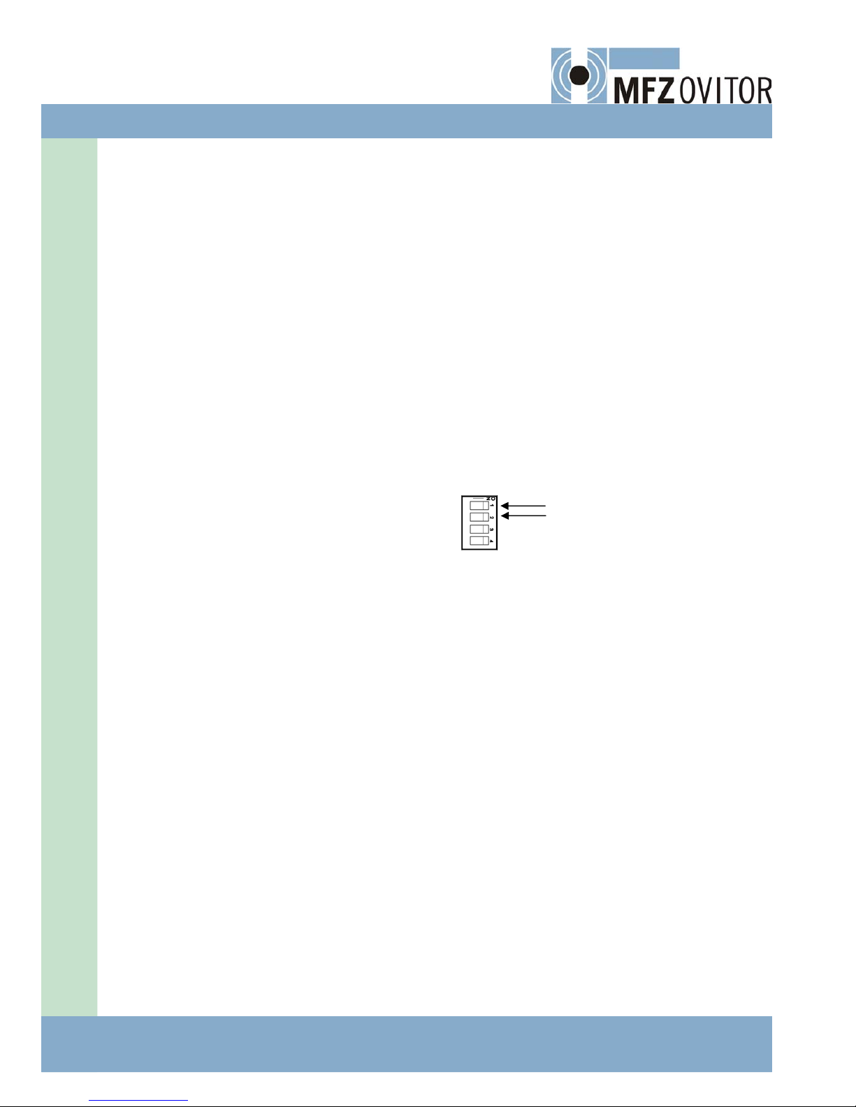
Itiseasiertoadjustthelimitswhenthecontrolissettohold‐to‐run.Thecontrolcanbeswitchedtohold‐to‐runintheopen
directionusingshortcircuitplugNo.2ofterminalJ6andinthecloseddirectionwithplugNo.3ofterminalJ6.Whenthe
shortcircuitplugisinplacethecontrolwillswitchtohold‐to‐run.Oncethelimitshavebeenset,theshortcircuitplugscan
beremovedandthecontrolwillchangetoimpulsedirected.
4.2.AUTOMATICCLOSING
Bymeansofaselectorswitchconnectedtoterminalblocks12and13ofthecontrolunit,adoororsimilarcanbemadeto
closeautomaticallyfromtheopenorhalf‐openposition,whenthecontactsoftheswitchareclosed.Whenthecontactsof
theswitchareopen,noautomaticclosingwilltakeplace;cf.drawingno.337L.WithjumpersNo.2and3ofterminalJ7auto‐
maticclosingcanbechosenfromeitherhalf‐openorfully‐openpositionorboth.IfbothjumpersNo.2and3areofforon,
automaticclosingworksfromeitherposition.IfjumperNo.2isonand3isoff,automaticclosingworksfromfully‐openposi‐
tion.IfjumperNo.3isonand2isoff,automaticclosingworksfromhalf‐openposition.Operationwithautomaticclosingis
notpermittedwithoutsufficientsafetydevices.
Thedelaybeforeautomaticclosing,thatis,thetimethedoorstaysopen,issetwithrotaryswitchS133intheupperright
cornerofboardE6‐2LandwithterminalJ4jumperNo.8.NOTE!Whentherotaryswitchisinposition0andthejumpernot
inplace,theautomaticclosingfunctiondoesnotwork.Thetimeisdeterminedaccordingtothetablebelowbytheposition
oftherotaryswitch.IfthecontrollerisequippedwiththeserviceterminalE6‐6‐02/3E,thedisplayshows,whentheposition
oftherotaryswitchischanged,foramomentthetext‘A80‘andafterthatthesettime.
4.BASICFUNCTIONS
S133positionStayopentime[s]
J4jumperno.8OFF
Stayopentime[s]
J4jumperno.8ON
S133positionStayopentime[s]
J4jumperno.8OFF
Stayopentime[s]
J4jumperno.8ON
0noautoclose90815500
11120917600
23180A20800
35240B251000
46280C301500
58320D402000
610360E503000
712400F603600
4.3.MONITORINGTHECLOSINGDRIVE
Fortheeventualitythattheclosebuttongetsstuck,thecontrolhasbeenequippedwithclosingdrivemonitoring.Ifthe
closebuttonsendsaconstantclosingimpulsewhilethedoorisopening,thedoorwillnotcloseimmediatelyfromtheopen
position,butthecontrolwillrequireeitheranewclosingimpulseinordertocloseoritonlyclosesafterthestayopentime
setforautomaticclosing.

8‐ControlUnitE6L/Rev6.11
4.4.RUNNINGTIMELIMITER
ThecontrolunitE6Lhas,asasafetydevice,arunningtimelimiterthatstopsthemotoraftertheexpiryoftherunningtime
requiredforanormalopeningandclosingmotion.Thepermittedrunningtimeissetatthestageofintroductionofthe
door,bytherotaryswitchS132intheupperrightcornerofboardE6‐2L;cf.drawingno.340L.Therunningtimeisdeter‐
minedaccordingtothefollowingtable,bythepositionoftherotaryswitch.Thepermittedrunningtimeissetat2...10s
longerthantherunningtimerequiredforthenormaltravelofthedoor.Ifthecontrollerisequippedwithserviceterminal
E6‐6‐02/3E,thedisplayshows,whenthepositionoftherotaryswitchischanged,foramomentthetext‘A130‘andafterthat
thesettime.
Ifthesetcontinuousrunningtimeofthemotorisexceeded,theredLEDH103islitandthedoorstops.Ifthecontrolleris
equippedwithserviceterminalE6‐6‐02/3E,thenwhiletheLEDH103islit,thedisplayshowsthetext‘E9‘.Thiscanhappen,
forexample,whentheslippingclutchofthedriveunitslipsaftertheforcerequiredbythedoorhassurpassedthesetvalue.
TheredLEDissituatedontheCPUboardE6‐2L,cf.drawingno.340L.Thefaultindicationdisappears,andtheLEDturnsoff,
whenthedoorisagaindrivenintheopeningorclosingdirection.Iftherunningtimelimiterstopsthedooragain,checkBE‐
FOREdrivingthedoorineitherdirectionthat:
• thedoorcanfreelymoveinitsguidetracksfromoneextremepositiontotheother;
• therearenoforeignobjectsbetweenthehinges,sections,etc.ofthedoor;
• thedoorhasnotfrozenimmobile;
• nothingelseispreventingthenormalmovementofthedoor;
• thedoorhasnotbeensetonmanualusewiththereleaseleverofthedriveunit.
Ifeverythingisinorder,drivethedoorintheopeningorclosingdirectionfromoneextremepositiontotheother,observing
thedoormovementthroughoutthetravel.Ifthefaultindicationisrepeated,theresistanceagainstmotionofthedoorhas
forsomereasonincreased,and/ortheslippingclutchworkingassafetydeviceofthedriveunitisslipping.Thetimecanbe
setalittlelonger,butitisalsoimportanttofindoutthereasonwhythetravellingtimesetatintroductionhasincreased.
4.BASICFUNCTIONS
S132positionMaxrunningtime[s]S132positionMaxrunningtime[s]
05860
17970
210A80
315B90
420C100
530D120
640E180
750F300
4.5.FUNCTIONOFTHE‘STOP’BUTTONINAUTOMATICCLOSING
IfautomaticclosingissetinthecontrolandiftheSTOPbutton,connectedtoterminals38‐39or40‐41or42‐43or44‐
45,isbeingpressedwhilethedoorstandsinitsopenposition,thiswillproducetheresettingofthesequenceforautomatic
closing.Asthebuttonisreleased,thetimecountrecommences,andthedoorclosesautomaticallyafterthesettime.Ifthe
stopbuttonconnectedtotheseconnectorsorthecover’sstopbuttonispressedformorethan5secondswhenthedooris
open,thedoorwillnotcloseautomaticallybutstayopen.Thedoorcanbeclosedagainwiththeclosebutton,whichresets
theautomaticclosingfunction.
12/10
ControlUnitE6L/Rev6.11‐9
IftheSTOPbuttonconnectedtoterminals34‐35or36‐37isbeingpressed,thesequenceforautomaticclosingdoesnot
start,butthedoorstaysopen.Thesituationisclearedbypressingtheclosebutton,uponwhichthedoorclosesandfunc‐
tionsnormallyagain,sothatthenexttimeitclosesautomaticallyfromtheopenposition.Normally,thesafetymicro‐switch
ofthemanualusedisengagementlever,theslackcableswitchorasimilarsafetydeviceisconnectedtoterminals34‐35
and36‐37.Whenthefunctionofsuchasafetydevicereturns,automaticclosingcouldcauseadangersituation.Whenus‐
ingaprogramboardasanextradevice,thefunctioningofallstopbuttonscanbesettostopautomaticclosing.
4.6.REVERSALDELAY
Ifthedoorreceivesanopenimpulsewhileitisclosing,itstopsandopensafterashortdelaybeforereversal.Thereversal
delayaimsatreducingstrainsonthedoor,driveunitandfixations.If,however,theopenimpulsecomesfromthesafety
edgeasthedoorcollideswithanobstacle,thedooropensimmediatelywithoutdelay.Forsafetyreasons,nodelaycanbe
permittedinacollisionsituation.
4.7.SELECTIONOFRADIOCONTROLFORFULLORREDUCEDOPENING
TheradiocontrolontheterminalboardE6‐2LofthecontrolunitE6Lcanbeselectedtoopenthedooreithertofullopening,
ortoreducedopening.Theselectionisdonebyplacingthejumpersituatednexttotheradiosocketintothepositioncorre‐
spondingtothedesiredfunction.InthepositionX1theradiocontrolwillopenthedoorintofullopeningandintheposition
X2intoreducedopening,seedrawingsno.340Land337Lattheendpartofthismanual.Thepositionofthejumperistobe
changedonlywhentheboardisfreefromvoltage.Thechangingispracticallydonewiththinpointedpliers.
4.8.SINGLE‐BUTTONCONTROL(IMPULSECONTROL)
Thecontroldevicesofsingle‐buttoncontrolareconnectedtoterminals22...33accordingtodrawing337L.Theprogram‐
mingofsingle‐buttoncontrolisdonewiththeDIPswitchS131situatedintheupperrightcornerofboardE6‐2Landusing
shortcircuitplugno.1ofterminalJ7,cf.drawingno.340L.
Single‐buttonclosingissetbyturningswitchno.1ofS131intothepositionON.Nowthesingle‐buttoncontrolclosesthe
doorfromtheopenpositionandopensthedoorfromallotherpositions.Ifswitchno.1isturnedintothepositionOFF,sin‐
gle‐buttoncontrolsimplyopensthedoor.Ifavehicledetectoramplifier,forinstance,isconnectedtothesingle‐buttoncon‐
trol,theswitchiskeptinthepositionOFF.Single‐buttonstoppingissetwithswitchno.2ofS131.InthepositionONof
switchno.2,single‐buttoncontrolalwaysstopsamovingdooratthefirstpulseandopensitatthesecond,thatis,aclosing
doorstopsatthefirstpulseandopensatthesecond.Anopeningdoorstopsatthefirstpulseandreopensatthesecond.By
selectingthepositionOFFforswitchno.2,apulsefromthesingle‐buttoncontrolopensaclosingdoorimmediately,without
astoppingfunctionintheopeningdirection.TheswitchiskeptinthepositionOFFif,forinstance,avehicledetectorampli‐
fierisconnectedtothesingle‐buttoncontrol.
Single‐buttonclosingfromotherthantheopenpositionwillbedefinedbytheshortcircuitplugno.1interminalJ7.Inthat
casetheDIPswitches1and2mustbeinONposition.Theshortcircuitplugno.1beinginplacethedoor,stoppedwhen
movinginopendirection,startstocloseatthefirstimpulse.Thenextimpulsestopsthedoorandthenextoneopensit
again.Theoperationisnotallowedifitcancauseasafetyrisk.
4.9.LOADGUARD
ThecontrolunitE6Lisequippedwithaloadguard.Duringtheimplementationandservicingofthedoor,thecontrolsystem
isintroducedwiththepowerneededtomovethedoor.If,duringnormaluseofthedoor,thepowerdeviatesfromthein‐
troducedvalue,thecontrolwillreacttothechangedload.Anopeningdoorwillstopand,ifsorequired,closeafteraset
timeandaclosingdoorstopandre‐openiftheloaddeviatesfromtheenteredvalue.TheloadismeasuredwithaPNPtype
pulsesensorinthegear,whichmonitorstherotationspeed.Thesensorisconnectedtoterminals60(+24Vdc),61
(electronicszeropotential)and62(signal)ofboardE6‐2L.
10‐ControlUnitE6L/Rev6.11
Thecontrolsystemcontinuouslymeasuresthepowerneededtomovethedoor.Thesystemalsocontinuouslyupdatesthe
requiredpower,whichincreasesinnormalconditionsasthedoorwearsandthebalancechangesetc.Oncethepowerhas
increasedsothattherotationspeedhaschangedtomatchthegapbetweenthesetvalueandtheoriginalmeasuredvalue,
thecontrolautomaticallychangestohold‐to‐runandtheunitnotifiesaservicingrequest.Atthesametime,theredLED,
H103,blinksrapidlyapproximatelythreetimesasecondandiftheserviceterminalisconnecteditdisplaystheerrorcode,
“E 31”.Insuchacase,thepowerdiagramsmaynotbere‐runbutTHEDOORMUSTBESERVICED.Afterthedoorhasbeen
servicedandchecked,themotionpowerismeasuredaccordingtotheinstructionsbelow.
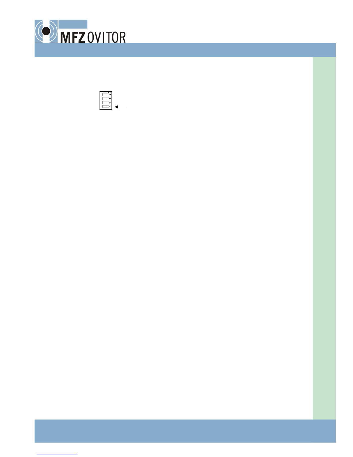
AloadguardoperationisselectedwithjumperNo.1ofterminalJ6.Iftheloadguardisinuse,jumperNo.1isdisconnected.
Iftheloadguardisnotinuse,jumperNo.1mustbeinstalled.
Astart‐updelayisdefinedfortheloadguard.Itsoperationistestedduringthestart‐updelay.Iftheguarddoesnotpassthe
testthedoorcontrolwillchangetohold‐to‐runinbothdirections.Onthesameboard,E6‐2L,theredLEDH103,willblinkat
arateof2secondsONand2secondsOFF.
Thesystemisalsosuitedtoinverteruse.InverteroperationisdefinedusingjumperNo.1ofterminalJ4.Duringinverteruse,
theshortcircuitplugisinplace.
4.BASICFUNCTIONS
JumperJ6/1LoadControlJumperJ4/1InverterUse
OFFControlONOFFDoornotininverteruse
ONControlOFFONDoorininverteruse
JumperJ4/4Start‐upDelay
OFF0,8seconds
ON1second
Jumper
J4/6
Jumper
J4/7
ClosingTime
OFFOFF0s
OFFON1s
JumperJ4/2
OFF
ON
Jumper
J7/4
OFF
OFF
Sensitivity
open
5%
8%
Jumper
J4/3
OFF
ON
Jumper
J7/4
OFF
OFF
Sensitivity
close
3%
6%
ONOFF2sOFFON12%OFFON10%
ONON6sONON16% ONON16%
Theloadguardstopstheopeningdooriftheloaddeviatesfromtheintroducedvalue.Toeasetheremovalofanobstacle,
thedoorcanbeclosedforasettimeaccordingtotheattachedtable.ThetimeisdefinedwithshortcircuitplugsNo.6and
7ofterminalJ4.IftheloadguardhasstoppedtheopeningdoortheredLEDH102blinksatarateof2secondsONand2
secondsOFF.Theserviceterminalthendisplaystheerrorcode,“E 20”.Thefaultdisappearswhenthedoorisopenedor
closedandtheoverloadhasbeenremoved.Thesensitivityoftheloadguardintheopendirectionisadjustedwithjumper
No.2ofterminalJ4andwithjumperNo.4ofterminalJ7,inaccordancewiththeattachedtable.Sensitivityisdefinedasa
percentageofthemeasuredvalues.
Theloadguardstopsandopenstheclosingdoorwithoutareversaldelayiftheloaddeviatesfromtheintroducedvalue.If
theloadguardhasstoppedandopenedaclosingdoor,theredLEDH102blinksatarateof2secondsONand2seconds
OFF.Theserviceterminalthendisplaystheerrorcode,“E 4”. Thefaultdisappearswhenthedoorisopenedorclosedand
theoverloadhasbeenremoved.ThesensitivityoftheloadguardinthecloseddirectionisadjustedwithjumperNo.3of
terminalJ4andwithjumperNo.4ofterminalJ7,inaccordancewiththeattachedtable.Sensitivityisdefinedasapercent‐
ageofthemeasuredvalues.
12/10
ControlUnitE6L/Rev6.11‐11
ThesizeoftheloadchangeintheoriginalmeasuredvaluesisdefinedusingjumperNo.5ofterminalJ4,inaccordancewith
attachedtable.Sensitivityisdefinedasapercentageofthemeasuredvalues.Iftheloadthedoorplacesonthegear
changesfromtheoriginal,introducedvaluebysomuchthattheset,permittedchangevaluesaresurpassed,theservice
terminaldisplaydisplaystheerrorcode,“E 31”.Simultaneously,theredLEDH103blinksquicklyontheE6‐2Lboard,repre‐
sentingadoorservicerequest.Atthesametime,thedoorcontrolswitchestohold‐to‐runintheopenandcloseddirection.
Inasituationlikethis,theloaddiagramsmustnotbere‐runbutTHEDOORMUSTBESERVICED.Afterthedoorhasbeen
servicedandchecked,anewintroductionrunisperformedwhichremovestheerrormessage.
JumperJ4/5LoadChange
OFF6%
ON10%
4.10.INTRODUCTIONRUN
Anintroductionrunisperformedduringdoorimplementationandservicing.Theintroductionrunisstartedbypressingthe
introductionrunstart‐upbutton,S5,betweenterminalsJ4andJ6orbysettingjumperNo.1ofterminalJ6inplacefora
whileandthenremovingitorcontinuouslypressingtheclosebuttonwhilethedoorisclosingandcontinuingtopressitfor
10secondsafterthedoorhasstoppedmoving.Ifpressingcontinuesformorethan22seconds–ifthebuttonjams,forex‐
ample–thecontrolwillnotswitchtointroductionrunmode.LEDsH103andH104blinkontheboardinturnandtheservice
terminaldisplayshowsthetext,“Lear”untiltheintroductionrunisfinished.While“LEAr”isdisplayed,the“OPEn”and
“CLOS”textsflashonthedisplaywhenthebuttonsareused.Thecontrolswitchestoautomatichold‐to‐run.Theintroduction
runproceedsinhold‐to‐runmodeinthefollowingmanner:
• Firstopenthedoortotheopenlimit.
• Nextcloseittotheclosedlimit.
• Re‐openthedoortotheopenlimit.
• Re‐closethedoortotheclosedlimit.
Openingandclosingmustbeperformedwithoutstopping,fromlimittolimitinhold‐to‐runmode.Makesurethatthesafety
photocellbeamisnotbrokenandthatthesafetyedgegivesapulseduringtheintroductionrun.Makesurebylookingthe
LEDsofthesafetyedgeandtheclosedlimitthatthedoorstopsinclosedpositionthroughthelimitswitch,notthroughthe
safetyedge:theLEDofclosedlimitgoesoutfirst.Whenneededshort‐circuitthesafetyedgeanddisablethesafetyedge
testingtemporarily.
Afterasuccessfulintroductionrun,theLEDsstopblinkingandthe“LEAr”textdisappearsfromtheserviceterminaldisplay.
Theintroductionrunisfinishedandthecontrolchangestoautomaticallyimpulsedirected.

12‐ControlUnitE6L/Rev6.11
5.SAFETYEDGE
5.1.FUNCTIONINGOFTHESAFETYEDGE
Ifapulseisreceivedfromthesafetyedgewhilethedoorisinclosingmovementbetweentheopenlimitandthesafetyde‐
vicelimit,theredLEDH102onboardE6‐2Llightsup;cf.drawingno.340L.Immediatelyafterthesafetyedgepulsethedoor
willopen.Ifautomaticclosinghasbeensetinthecontrol,thelatterprobeswiththesafetyedgefortheremovaloftheob‐
stacleinfrontofthedooredge.Thecontrollertriestoclosethedoor,andifapulsecomesindicatingcollisionagainstthe
safetyedge,thedoorwillreopen.Thecontroltriestentimesfortheremovaloftheobstacle,andiftheobstaclehasnot
disappearedfrominfrontofthedoor,thedoorwillremainopen.Thefirsttestingwilltakeplaceafterthetimesetfordelay
beforeself‐clearancedelay,andifthatisnotinuse,after60s.Thesecondtestingtakesplaceafterdoublethattime,the
thirdaftertriple,etc.Whenusingtheprogramboardasanextradevice,thetestingfunctioncanbeeliminated,sothatthe
doorremainsopenafterthesafetyedgepulseandwillnotcloseautomatically.InthiscasetheredLEDH102remainson.
TheLEDgoesoutandthedoorcloseswhenitisdrivenwiththeclosebutton.
5.2.TESTINGTHESAFETYEDGE
Themostimportantsafetydeviceofmovingdoorsisasafetyedgeinthecollidingedgeofthedoor.Apneumaticsafety
edgeistheonemostcommonlyused.ThecontrolunitE6Lisequippedwithasafetyedgetestingfunction.Thecontroller
teststhefunctioningofthesafetyedgeeverytimethedoorclosestightlyagainstthefloor,theframeorasimilarobstacle.If
nopulsecomesfromthesafetyedgeatthatmoment,thecontrolchangestohold‐to‐runintheclosingdirection.Theinfor‐
mationonthenon‐functioningofthesafetyedgeremainsinpermanentstorage,andthefaultindicationcanonlybecleared
withapulsefromthesafetyedge.
Iftherehasbeennopulsefromthesafetyedgeatthemomentthedoorreachedtheclosedposition,thered
LEDH104onboardE6‐2Llightsup,andthecontrolswitchesovertohold‐to‐runintheclosingdirection,cf.drawingno.
340L.IfthecontrolisequippedwithserviceterminalE6‐6‐02/3E,thedisplayshowsthetext‘E5‘whileH104ison.TheLED
H104goesoff,whenapulsecomesfromthesafetyedge.
Thefunctioningofthesafetyedgetestingcanbeobservedbydetachingthepressurehosecomingfromthesafetyedgeto
thepressureswitchandafterthisdrivingthedoorintotheclosedposition.Afterthedoorstopsintheclosedposition,the
redLEDH104mustlightup.IftheLEDdoesnotlightup,eitherthetestingofthesafetyedgehasbeenprogrammedoff,or
themembraneofthepressureswitchhasgotaconcussion,sothatthepressureswitchstillgivesapulse.Thepulsefromthe
safetyedgecanbeobservedfromthegreenLEDH47goingout,cf.drawingno.336L.Theeyedoesnotcatchtheveryshort
pulsewhichthelogic,however,recognises.Inaddition,wheneverapulsecomesfromthesafetyedgewhilethedoorisclos‐
ingbetweentheopenlimitandsafetydevicelimit,theredLEDH102ontheboardE6‐2Llightsupaccordingtosection
FUNCTIONINGOFTHESAFETYEDGE,cf.drawingno.340L.Ifnecessary,terminals46and47ofthesafetyedgecanbeshort‐
circuitedduringcontrolofthetesting,cf.drawingno.336L.Thecontrolofthistestfunctionmustbedonewithgreatcare,
asthedoorisatthattimebeingdrivenwithoutanysafetyfunction.
Incaseswheretherearenosafetyedgesortheydonothitanything,e.g.withtrafficbarriers,thesafetyedgetestingfunc‐
tioncanbeprogrammedoff.TheeliminationofthesafetyedgetestingisdonewiththeDIPswitchS131situatedintheup‐
perrightcornerofboardE6‐2L,cf.drawingno.340L.Turningswitchno.3ofS131intothepositionOFFcancelsthesafety
edgetesting.InthepositionONofswitch3,thesafetyedgetestingisinfunction.Ifthecontrollerisequippedwithservice
terminalE6‐6‐02/3E,thedisplayshows,whenthepositionoftheswitchischanged,forashortmomentthetext‘L60‘and
afterthat‘OFF‘or‘ON‘accordingtothepositionoftheswitch.
5.3.PNEUMATIC/ELECTRONICSAFETYEDGE
ControlunitE6Lcanbeequippedwithapneumaticand/orelectronicsafetyedge.Thepneumaticsafetyedgeisusedwhen
itsconditioncanbemonitoredinaccordancewiththesection,“SAFETYEDGETESTING.”Thepneumaticsafetyedgeiscon‐
nectedtoterminals46and47.Ifthesafetyedgeisnotused,theconnectorsmustbeshortcircuitedwitheachother.
12/10

ControlUnitE6L/Rev6.11‐13
Theelectronicsafetyedgeisusedwhenthereisnotestpulsefromthesafetyedgewhenthedoorisclosed,e.g.slidingand
foldingdoors.Tocontrolthecondition,theelectronicsafetyedgerequiresaseparatemonitoringunitSEM2whichisin‐
stalledusingconnectorX18ontheleftedgeoftheE6‐2Lboard.Inadditiontothemonitoringunit,thecontrolsystem’sown
safetyedgetestingcanbeused.Iftheelectronicsafetyedgeemitsapulsewhenittouchesthefloorortheequivalent,the
door’scontrolsystemwilltestthepulsefromthesafetyedge.Inthisway,thesafetyedgeoperationisdouble‐monitored.If
theelectronicsafetyedgeisnotused,thepinsoftheterminal,J3,nexttothesocketmustbeshortcircuitedwithaplug.
8,2kΩ1%
Whenthereisonly
oneelectronic
safetyedgeinuse,
theothermustbe
replacedwith
8.2kΩ1%resistor
SafetyEdge
X18
Figure3.SEM2.Connectionofelectronicsafetyedge.
SinceSEM2has2channels,itcanbeusedfortheindicationofoneortwoelectronicsafetyedges’obstaclerecognitionand
themalfunctionindicationforthesafetyedgeoritscabling.ThesensorsconnectedtoSEM2musthavean8.2kΩterminal
resistor.Withthehelpoftheidlecurrentthatrunsthroughtheterminalresistor,theSEM2canindicateapossiblesensor
circuitdisconnectionormalfunction.Alwaysmakesurethattheterminalresistorisinstalledonthefinalendofthesafety
edge.Youcanalsoconnectseveralsafetyedgesinseriesbutthelastsafetyedgeintheseriesmustbeconnectedwithan
8.2kΩterminalresistor.Whenconnectingsafetyedges,pleasenotethatthecircuitresistanceoftheusedcablesmustbe
nomorethan100Ω.
SEM2hastwoseparate,identicalsupervisingcircuitsformonitoringsafetyedgestatus.Bothcircuitsmonitorbothsafety
edges.Ifonesupervisingcircuitbreaksasingleorseveralcomponents,theothercircuitcanindicatetheobstaclerecogni‐
tionormalfunctionofbothsafetyedges.
WhentheSEM2monitoringunitisusedforonlyoneelectronicsafetyedge,theothersafetyedgemustbeconnectedwith
an8.2kΩ1%resistor.Innormaldeliveries,theresistorisready‐connectedwithbothconnectorsandthesinglesafetyedge
isconnectedinaccordancewiththefigure.Ifthereisonlyonesafetyedge,SEM2monitorsitusingbothsupervisingcircuits.
Whentheamplifierunitisconnectedtothesupplyvoltageandsafetyedgesandtheircablingisundamaged,noLEDswillbe
oninthemonitoringunitandthecircuitofthecontrolunitwillbeunbroken.OnlytheH47LED,indicatinganunbrokencir‐
cuit,willbeswitchedoninthedoor’sboard,E6‐2L.Whenthesafetyedgemeetsanobstacleortheresistanceoftheedge
circuitdrops,theyellowLEDs,H1andH3,willturnoninthemonitoringunit,thecontrolsystem’scircuitwilldisconnectand
theLED,H47,willswitchoff.Ifthesafetyedgecircuitisdisconnectedoritsresistanceincreases,theredLEDs,H2andH4,
willswitchoninthemonitoringunit,thecontrolsystem’scircuitwilldisconnectandtheLED,H47,willswitchoff.
IfonlyoneoftheLEDs,H1,H2,H3orH4,isswitchedonthismeansthatthereisamonitoringunitmalfunction,thecontrol
system’scircuitwilldisconnectandtheLED,H47,willswitchoff.Insuchacase,themonitoringunitmustbereplaced.
14‐ControlUnitE6L/Rev6.11
5.SAFETYEDGE
Theoperationofthesafetyedgesystemandthemonitoringunitmustbecheckedregularly,forexamplewheneverthe
doorisserviced.Whenthesafetyedgegivesapulsee.g.duetocontactwithahand,thedoor’scontrolsystemmustreact
accordingtotheselectedoperatingmode.Whentheothersafetyedgecableisdisconnected,thedoor’scontrolsystem
mustreactaccordingtotheselectedoperatingmode.Thedoorandmonitoringunitmayonlybeservicedbyanauthorised
servicetechnician.
5.4.FOLDINGDOOR
Ifthecontrolleddoorisafoldingdoorwithsafetyedgesinthecollidingedgeshittingeachotherbeforethefoldsofthe
doorhavestraightenedoutintothefullclosedposition,thestoppingeffectofthesafetyedgemustbeprogrammedoff.
TheeliminationisdonewiththeDIPswitchS131situatedintheupperrightcornerofboardE6‐2L,cf.drawingno.340L.
Turningswitchno.4ofS131intothepositionONby‐passesthesafetyedgeselectricallyatthefunctioningzoneofthe
safetydevicelimitswitch.Ifthesafetyedgesdonothiteachother,theswitchisleftinthepositionOFF.Ifthecontrolleris
equippedwithserviceterminalE6‐6‐02/3E,thedisplayshows,whenthepositionoftheswitchischanged,foramoment
thetext‘L50‘andafterthat‘OFF‘or‘ON‘accordingtothepositionoftheswitch
12/10

ControlUnitE6L/Rev6.11‐15
6.PHOTOCELLS
6.1.THEAMPLIFIERFORATRANSMITTER‐RECEIVERTYPESAFETYPHOTOCELLINTEGRATEDWITHTHE
ELECTRONICSBOARD
Anamplifierforatransmitter‐receivertypesafetyphotocellisintegratedwithelectronicsboardE6‐2L.Theamplifier,atrim‐
merforamplifieradjustmentandtransmitterandreceiverterminalsarelocatedontheleft,uppercorneroftheboard.The
transmitterandreceiverareconnectedaccordingtothefollowingfigure4.
Leftconnectors1and2oftheconnectorareinstalledwiththetransmitter(LT),theredsignalcabletoconnector1andthe
blacksignalcabletoconnector2.Therightsideconnectorsoftheconnectorareconnectedwiththereceiver(LR),the
sheathorblackcabletoconnector3andtheyellowsignalcabletoconnector4.NOTE!Theconnectorhasfiveconnectors
andthemiddleoneisleftempty.
Thephotocellamplifieristunedasfollows:
S301ON(pinsshortcircuitedwithaplug):widedoorway(greateramplifica‐
tion)
S301OFF(withoutashortcircuitplug):narrowdoorway(smalleramplifica‐
tion)
R308:adjustmentofamplification.
H300(green):lightsupwhentheamplificationisadjustedtosufficientmagni‐
tudewiththeR308andwhenthelightbeamisintact.
H301(green):lightsupwhenthephotocellamplifierhasoperatingvoltage.
H302(green):goesoutwhenthephotocellamplifiercontactopens.
TheLEDsarelocatedabovetheextradeviceterminalsontheleftedgeoftheconnector.
Thecorrectadjustmentofthephotocellamplifierisperformedattheinstallationsitebytestingwhetherthephotocellfunc‐
tionsreliably.Theamplificationmaynotbesettooweaknortoostrong.Thereceivershouldbeinstalledontheshadier
side,outofdirectsunlight.
Ifitisnecessarytolengthenthecablesofthetransmitterorthephotocellreceiver,thetransmittercableshouldgenerally
belengthened.Thetransmitterandreceiverconductorsshouldnotruninsidethesamecablesheath.Ifthismustbedone,
thecablemustbeofthedouble‐protectedtype.Fromtheoperationalpointofview,themostreliablewayistoinstallapro‐
tectedcableforeach.
ThesimplestwaytoalignthetransmitterandthereceiveristoconnectamicroammeterinserieswiththereceiverintheAC
band.Thetransmitterandthereceivershouldbeadjustedsothatthecurrentshownbythemeterisasgreataspossible,
thusindicatingtheoptimumalignment.
Ifanintegratedphotocellisnotused,shortcircuitplugNo.4ofterminalJ6mustbeconnected.
6.2.TESTINGPHOTOCELLS
OneofthefeaturesofcontrolunitE6Lcomprisesthetestingoftheclosingsafetyphotocelloperation.Thesafetyphotocell
istestedwheneverthedooropens.Withanintegratedphotocell,photocelltestingisperformedbydisconnectingthetrans‐
mittervoltagethatcorrespondstothedisconnectionofthephotocellbeam.Thetestingoperationisvisiblewhenthedoor
opensafterthegreenH56LEDhasgoneoff.IftheLEDdoesnotgooffbecauseofamalfunctionorthesafetycircuitinthe
closeddirectiondoesnotdisconnect,thecontrolchangestohold‐to‐runinthecloseddirection.Simultaneously,thered
LED,H104,blinksrapidly.Ifthecontrolhasaserviceterminal,itdisplaystheerrorcode“E 30”.Theerroralarmdisappears
whenthephotocelltestingissuccessful.Ifnophotocelltestisperformed,shortcircuitplugNo.6ofterminalJ6mustbe
connected.Safetyphotocelloperationmustbecheckedduringeachservicingoratleastonceayear.
Figure4.
LRLT
S301
R308
43
2
1
LT LR
red
black
sheath
yellow

16‐ControlUnitE6L/Rev6.11
Inadditiontotheintegratedphotocell,theE6‐2Lboardhasaseparatesocket,X103,whichcanbeconnectedinserieswith
otheroutsidephotocells,forexampleaseparatesinglechannelE6‐4oraseparatetwo‐channelEU2‐4oraseparatemirror
photocell.Whenconnectingamirrorphotocell,youneedaseparatescrewterminalpushedintoconnectors55and56of
connectorX103.Theelectronicszeroforthemirrorphotocellcanbeacquiredfromconnector58.Ifaseparatephotocellis
notused,connectors55and56ofconnectorX103mustbeinstalledwithatwo‐partscrewterminalwhoseconnectorsmust
beshortcircuitedwitheachother.
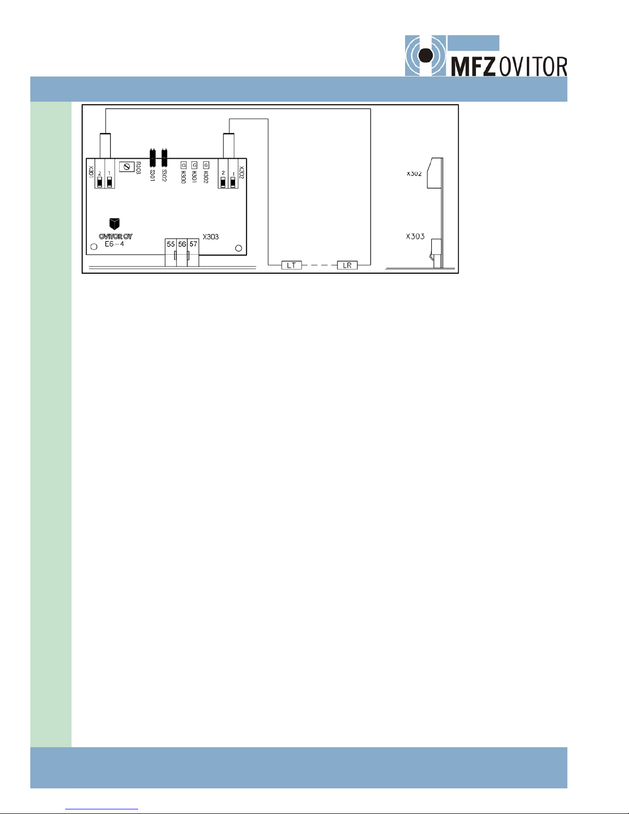
6.3.SEPARATESAFETYPHOTOCELLE6‐4,SINGLE‐CHANNEL
TheseparatesafetyphotocellamplifierboardE6‐4isinstalledintotheplug‐insocketX103intherightedgeofboardE6‐2L,
cf.drawingno.340L.IfaterminalblockwithajumperhasbeeninstalledinsocketX103,theterminalblockisfirstremoved
bypullingout,andthenterminalX303ofthephotocellamplifierboardispushedintosocketX103sodeepthatitsclawsget
intoperfectgripwiththecorrespondingclampstepoftheX103.Installedinanormalway,theboardonlyfitsinoneposi‐
tion.ThecomponentsideoftheboardfacestheE6‐2LsideoftheCPUboard.Thetransmitterandthereceiverareinstalled
ontheamplifierboardaccordingtothewiringdiagram.Thereceiver(LR)ismountedonterminalX301,thesheathontopin
1andthesignalconductor(yellow)ontopin2.
Thetransmitter(LT)isconnectedtotheterminalX302,thesignalconductor(red)ontopin1andthesheathortheblack
conductorontopin2.NOTE!Theorderofpinsisfromrighttoleft.Ifanothertypeofphotocellisused,itisinstalledaccord‐
ingtothewiringdiagramandtheinstructionofdrawingno.340L.
PhotocellamplifierE6‐4istunedupasfollows(cf.figure5):
• S301ON(pinsshort‐circuitedwithaplug):widedoorway(greateramplification);
• S301OFF(withoutashortcircuitplug):narrowdoorway(smalleramplification);
• S302ON(pinsshort‐circuitedwithaplug):thephotocellamplifierswitchedoffwhenthephotocellbeamisbroken,
so‐calledlightoperation.TheS302istobeswitchedintheONpositionincaseofasafetyphotocell;
• S302OFF(withoutshortcircuitplug):photocellamplifierisswitchedoffwhenthephotocellbeamisNOTbroken;
so‐calleddarkoperation.TheS302isconnectedintheOFFpositionwhentheamplifierisusede.g.asanopening
photocellinaseparatesocketFC2;
• R308:adjustmentofamplification;
• H300(green):lightsupwhentheamplificationisadjustedsufficientlygreatwiththeR308andwhenthelightbeam
isintact;
• H301(green):lightsupwhenthephotocellamplifierhasgotoperatingvoltage;
• H302(green):goesoutwhenthephotocellamplifiercontactopens
Thecorrectadjustmentofthephotocellamplifierisdoneattheplaceofinstallationbytestingareliablefunctioningforthe
photocell.
• Theamplificationmaynotbesettooweaknortoostrong.
• Thereceivershouldbeinstalledontheshadiersidesothatsunlightdoesnotshineonitdirectly.
• Ifitisnecessarytolengthenthecablesofthetransmitterorthereceiverofthephotocell,thecableofthetransmit‐
tershouldgenerallybelengthened.Thetransmitterandreceiverconductorsshouldnotruninsidethesamecable
sheath.Ifthismustbedone,thecablemustbeofdouble‐protectedtype.Fromthepointofviewofoperation,the
mostreliablewayistoinstallforboththeirownprotectedcable.
• Thealignmentofthetransmitterandthereceiverismostsimplydonesothatamicroampere‐meterisconnectedin
serieswiththereceiverintheACband.Thetransmitterandthereceiverareadjustedsothatthecurrentshownby
themeterisasgreataspossible,thusindicatingtheoptimumalignment.
6.PHOTOCELLS
12/10
ControlUnitE6L/Rev6.11‐17
INSTALLATION
POSITION
TRANSMIT‐
TER
RECEIVER
R308=ADJUSTMENTOFAMPLIFICATION
S301ON‐WIDEDOORWAY
OFF‐NARROWDOORWAY
S302ON‐LIGHTOPERATION
OFF‐DARKOPERATION
Figure5.PhotocellamplifierE6‐4
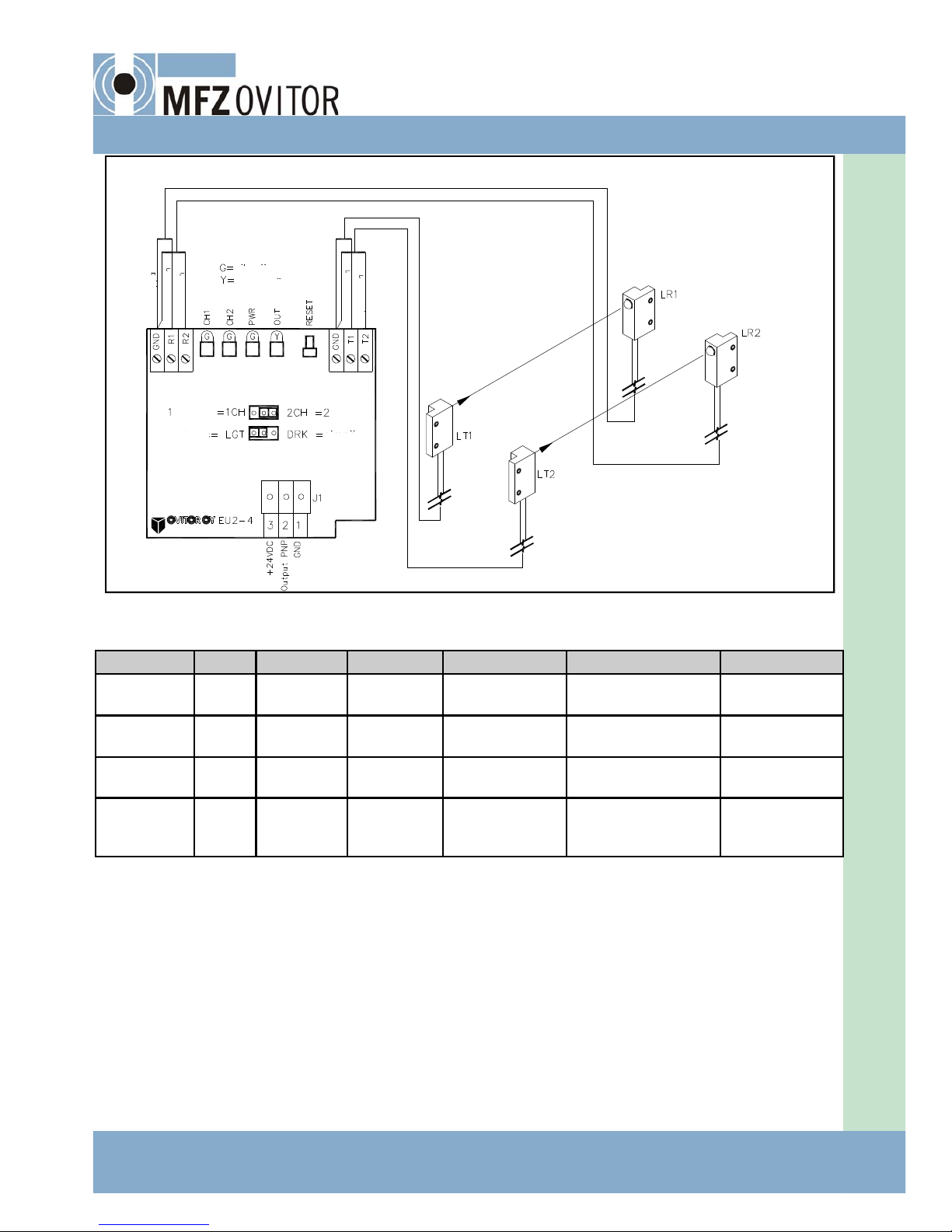
6.4.SEPARATESAFETYPHOTOCELLEU2‐4,1OR2CHANNELS
ThesafetyphotocellEU2‐4isdirectlysuitableforthecontrolunitE6L.Theamplifierboardwilloperatein1or2channel
modedependingofthepositionoftheshortcircuitplug1CH/2CH.Themiddlepinofthe3‐pinterminalisconnectedtopin
1CH(1channel)ortopin2CH(2channels).In1channelmodethetransmitterisconnectedtoterminalsT1andGND,the
receivertoterminalsR1andGND.In1channelmodethelevelindicatingLEDCH2isnoton.
TheselectionbetweenlightanddarkoperationmodeismadebytheshortcircuitplugDRK/LGT.Themiddlepinofthe3‐
pinterminalisconnectedtopinDRK(dark)ortopinLGT(light)accordingtotheoperationinuse.Incaseofsafetyphotocell
theconnectionislight.
ThetypeofthetransmitterofsafetyphotocellEU2‐4isLT01‐WS‐15M,thetypeofreceiverisLR02‐WS‐15M.Thetransmit‐
terLT‐WS‐15MandthereceiverLR‐WS‐15MofthepreviousphotocelltypesE6‐4,PA‐seriesandMPA‐series,arenotdirectly
suitabletousewithEU2‐4transmittersandreceivers,buttheymustalwaysbeusedastheirownpair.Whenusingtransmit‐
tersandreceiversofthepreviousphotocelltypesinthenewamplifierEU2‐4,inordertowork,theymustbeusedastheir
ownpair.Whenusingnewtransmittersandreceiverswithanamplifierofprevioustypes,pleasecontactOVITOROY.
ThesafetyphotocellamplifierboardEU2‐4isinstalledintotheplug‐insocketX103intherightedgeofboardE6‐2;see
illustration1.IfaterminalblockwithajumperhasbeeninstalledinsocketX103,theterminalblockisfirstremovedbypull‐
ingitout,andthenterminalJ1ofthephotocellamplifierboardispushedintosocketX103sodeepthatitsclawsgetinto
perfectgripwiththecorrespondingclampstepoftheX103.Installedinanormalway,theboardonlyfitsinoneposition.
ThecomponentsideofboardEU2‐4facesthecomponentsideoftheE6‐2Lboard.Thetransmitterandthereceiverofthe
photocellareconnectedontheamplifierboardaccordingtothewiringdiagramandillustration6.Theopeningphotocell
amplifierboardismountedonaseparatesocketFC2.
PhotocellamplifierEU2‐4istunedupautomaticallywhenthealignmentsoftransmittersandreceiversarecorrectandthe
amplifieroperatingvoltagewillbeswitchedon,ortheRESETbuttonontheboardwillbepushed.Whenswitchingpower
on,thegreenLEDPWRintheamplifierlightsup,andiftransmittersandreceiversarecorrectlyaligned,alsotheyellowLED
OUTlightsupindicatingbeamunity.SimultaneouslytheoperationlevelindicatinggreenLED’sCH1andCH2flashslowly
andafterawhilekeeponlightingconstantly.IfthelevelindicatinggreenLED’scontinuouslyflashslowly,thephotocellam‐
plificationisatmaximumrange.Thereasonforthatisnormallyawrongalignmentoftransmittersandreceiversanditmust
bechecked.IfthelevelindicatinggreenLED’sflashquickly,thereceiversareinfluencedbyasevereextraneousdisturbance.
InthatcasetheyellowLEDOUTgoesout.
18‐ControlUnitE6L/Rev6.11
6.PHOTOCELLS
LED’sFUNCTIONINGINLIGHTOPERATIONMODE
Figure6.PhotocellamplifierEU2‐4
LR=receiver
LT=transmitter
LEDColourOnOffFlashingslowlyFlashingcontinuouslyFlashingquickly
LevelLEDCH1GreenBeam1solidBeam1
broken
TuningAmplificationatmaxExtraneous
disturbance
LevelLEDCH2GreenBeam2solidBeam2
broken
TuningAmplificationatmaxExtraneous
disturbance
Operation
voltagePWR
GreenInorderMissingFaultyamplifierFaultyamplifierFaultyamplifier
OutputOUTYellowBeamssolidBeambroken
orextraneous
disturbance
Swingingobstacle
breaksthebeam
Swingingobstacle
breaksthebeam
Swingingobstacle
breaksthebeam
• Whenusingtwochannelsthebothtransmittersmustbeonthesameside,seefigure6.
• Thereceiversshouldbeinstalledontheshadiersidesothatsunlightdoesnotshineonthemdirectly.
• Ifitisnecessarytolengthenthecablesofthetransmitters/receiversofthephotocells,thecablesofthetransmitterare
tobelengthened.Thetransmitter/receiverconductorsshouldnotruninsidethesamecablesheath.Ifdone,thecable
mustbeofdouble‐protectedtype.Themostreliablewayistoinstallforallofthemtheirownprotectedcable.
• Thealignmentofthetransmitterandthereceiverismostsimplydonebyconnectingamicroammeterinserieswiththe
receiverintheACband.Thetransmitterandthereceiverareadjustedsothatthecurrentshownbythemeterisasgreat
aspossible,thusindicatingtheoptimumalignment.
• Thefunctioningofphotocellisbesttestedbybreakingforinstancewithahandthebeamandlookingatthesametimeif
thechannellevelLEDgoesout.Whenclosingthedoormuststopandopenwhenthephotocellworks.
Green
sheath
DARK
channel
LIGHT
Yellow
yellow
yellow
black
red
red
channels
12/10

ControlUnitE6L/Rev6.11‐19
6.5.USINGPHOTOCELLAMPLIFIERSE6‐4ANDEU2‐4ASOPENINGPHOTOCELLS
PhotocellamplifiersE6‐4andEU2‐4canalsobeusedasopeningphotocells,inwhichcasetheamplifierisintheso‐called
darkoperationmode.Theselectionofthedarkoperationmodeisdonewiththeshort‐circuitplugontheamplifierboards,
ashasbeenexplainedinthesafetyphotocellinstructionsabove.Theinstallationandwiringofthephotocelltransmitters
andreceiversarethesameasinsafetyphotocelloperation.Inopeningphotocelloperation,theamplifierisinstalledinthe
separateamplifierbaseFC2,installedwithDin‐rail,inaccordancewithfigure7,NOTinthesafetyphotocellbaseX103pre‐
installedonthecircuitboard.
Theterminalsontheamplifierbaseareconnectedtothedesiredopeningterminals.Whenmakingthewiring,remember
thecorrectdirectionofcurrentontheamplifierboard.Thevoltagetobecontrolledisinputontheamplifierbasetotermi‐
nal255,andthecontrollingvoltageisoutputfromterminal256.Thezeropotentialofelectronicsisconnectedtoterminal
257.Whenrequired,thedirectionofcurrentmustbecheckedinthediagramoftheinnergroupingofcontroldevices,in
thefinalsectionofthemanualconcerned.Below,thereisanoptionforthewiringoftheamplifierbaseoftheopeningpho‐
tocell(figure8).
Figure7.AmplifierbaseFC2Figure8.WiringoftheamplifierbaseFC2
DIN‐railincontrolunit
TheamplifierbaseFC2canalsobeutilisedwhenseparateidlecurrentsafetydevicesareconnectedinseries,suchasa
safetyphotocellandavehicledetector.Itmustberememberedinserialconnectionthatthephotocellamplifierisfirstinit
andtherelayoutputofthevehicledetectorafterit.Terminal255ofamplifierboardFC2isconnectedtoscrewterminal55
addedtothebaseofthesafetyphotocellofthecentralboard.Terminal256ofamplifierboardFC2isconnectedtoonepole
oftheopeningcontactoftherelayoutputofthevehicledetector.Theotherpoleoftheopeningcontactoftherelayoutput
ofthevehicledetectorisconnectedtoscrewterminal56addedtothebaseofthesafetyphotocellofthecentralboard.
Terminal257ofamplifierboardFC2isconnectedtoaterminalinzeropotentialofthecentralboard.

20‐ControlUnitE6L/Rev6.11
7.INSTALLATIONOFANEXTRADEVICEBOARDEQUIPPEDWITHANEDGETERMINAL
TheedgeterminaloftheextradeviceboardisconnectedtothefreeBUSterminalofboardE6‐2L.TheterminalsareBUS1,
BUS2andBUS3.Thedirectionofinstallationisshowninillustration9.Theextradeviceboardterminalmustfitcompletely
intotheBUSterminal.CheckthatthegreenLEDontheextradeviceboardlightsup.Thisshowsthattheprogramhasrecog‐
nisedtheboardtypeandthattheboardisreadyforoperation.
IftheLEDdoesnotlightupandthereareseveralextradeviceboardsinthecontroller,youcansearchforthedefective
boardasfollows:
1.Switchpoweroffofthecontroller.
2.RemoveallextradeviceboardsfromterminalsBUS1,BUS2andBUS3.
3.Reinstalloneboardatatime.
4.Switchpowerbackon.
5.IftheLEDlightsup,theboardinquestionisOK.
6.Repeatsteps1...5forallextradeviceboards.
7.IftheLEDdidnotlightupinanyextradeviceboard,thefaultisinthebasiccontroller.
TheserviceterminalequippedwithadisplaydoesnothaveaLED.Instead,afunctioningboardwillshowanumericseriesor
atextonthedisplay.Inadefectiveterminal,thedisplayisoutoritssegmentsarelitsporadically.
BOARD
E6‐2L
Installingtheboardbackwardsisnotpossiblebe‐
causeofthedoweledholeintheextradeviceboard
andacutpininthecorrespondingplaceoftheBUS
Extradeviceboardcompo‐
nentside
Figure9.Installationofanextradeviceboard
12/10
Table of contents
Other MFZ Ovitor Gate Opener manuals


Popular Gate Opener manuals by other brands

Comunello Automation
Comunello Automation ABACUS 220 Installation and user manual

Erreka
Erreka VIVO-M201M Quick installation and programming guide

Centsys
Centsys D3 user guide

Maximum Controls
Maximum Controls Max Megatron 1400 Installation and owner's manual

DoorKing
DoorKing 6004 manual

FAAC
FAAC 740 D manual


