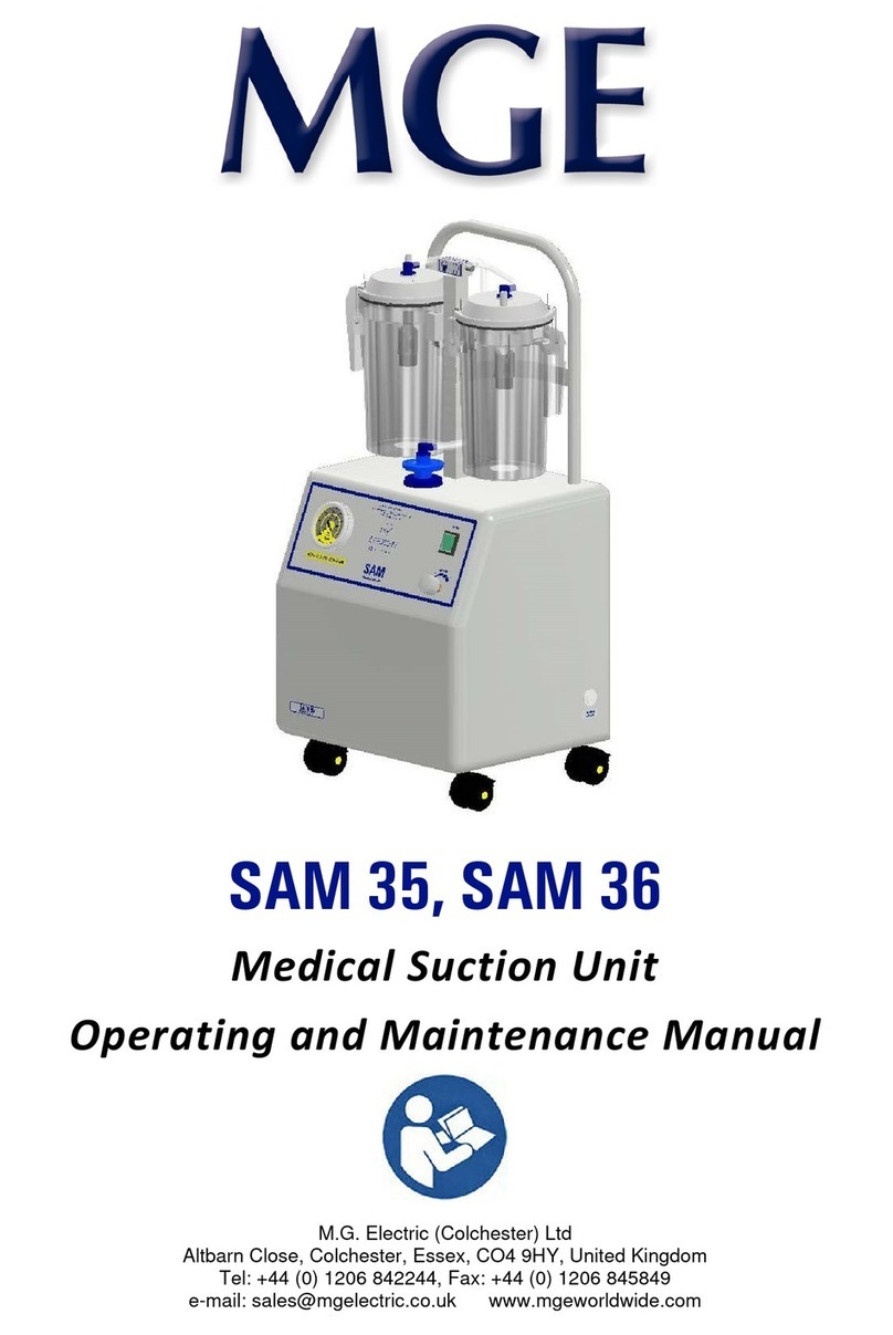
MGE UPS Systems SAM Operating instructions

SAM e.p.s
Portable Suction
Operating and Maintenance Manual
MG Electric (Colchester) Ltd
Altbarn Close, Colchester, Essex, CO4 9HY, United Kingdom
el: +44 (0) 1206 842244, Fax: +44 (0) 1206 845849
e-mail: sales@mgelectric.co.uk www.mgeworldwide.com

SAM e.p.s – UK
Operation and Maintenance Manual
Manual 156 - Issue 08 Page 2 of 28
Dear Customer,
We take this opportunity to thank you for purchasing a SAM Medical Suction Unit.
Please read the operating instructions and listed precautions thoroughly before attempting to operate the unit.
MG Electric manufactures its range in accordance with the requirements of BS EN ISO 9001 and BS EN ISO
13485.
I DEX
INS RUC IONS FOR USE
General Description
Preparation for Use
Operator Controls
Fluid Collection Container
Internal Battery
Operation of the SAM e.p.s
After Care of the SAM e.p.s
Carrying the SAM e.p.s
MAIN ENANCE
Daily Procedures
Weekly Maintenance
Monthly Maintenance
Service Maintenance
Battery Replacement
ransport and Storage
Flow Rates
Effect of Altitude
Quick est for Unit Functionality
Over-Vacuum Safety Cutout
Cleaning and Replacement of Parts
Circuit Diagram
Power Supply
Battery
Battery Storage
Process Control and Service
Resetting the Unit
Flow Diagram
OP IONS AND RECOMMENDED SPARES
Spares
Consumables
General Layout
rouble Shooting
ECHNICAL SPECIFICA ION
General Dimensions
Electromagnetic Compatibility (EMC)
MGE DA A CAP URE ON SAM E.P.S - MSP 1456
Equipment Requirements
Method
Notes
Other Products in the SAM Range –
Research and Development

SAM e.p.s – UK
Operation and Maintenance Manual
Manual 156 - Issue 08 Page 3 of 28
Definition of symbols used in these instructions -
he Instruction for Use must be referred to!
Manufacturers’ details and date of
manufacture.
Warning, Electricity
Disposal in accordance with directive
2012/19/EU
ype B applied part.
Ingress Protection -3- Ingress against Particulates
Ingress Protection -4- Ingress against water.
Caution! Or Warning
Dangerous voltage.
Warning
he SAM e.p.s must never be operated in the presence of flammable gas, or without a suitable filter.
Only use the unit in environmental conditions as specified in the maintenance section. Do not
immerse the unit in water or other liquids – this may cause damage and create an electrical hazard.
Do not pump cleaning solution through the unit. Isolate the mains supply before cleaning the unit.
Isolate the mains supply before removal of rear cover! Only collection systems that are approved by
MG Electric can be used with the SAM e.p.s. No modification of this equipment is allowed.
I STRUCTIO S FOR USE
BEFORE operating your new SAM e.p.s unit please read the following instructions carefully.
Become thoroughly familiar with the operation and maintenance of the unit before using. Only persons trained
in its use should operate the unit.
Do not block the exhaust outlet at the rear of the unit during use, as this will cause low flow and possible
damage.
IMPORTA T - The battery must be connected before initial use of the unit –
Refer to the installation sheet with the battery.
Remove the battery cover – connect the battery to the connectors located in the compartment. Install the
battery, locating the connectors inside the aperture on the right. Replace the cover and charge the unit. he
unit must be reset by turning the unit ON and then OFF.
Return of Medical Equipment
Should you wish to return any equipment to MG Electric (Colchester) Limited, or one of our designated
distributors, Health Service Guideline HSG (93) 26 Decontamination of equipment (prior to
inspection, service or repair) must be adhered to. Failure to follow this guideline will invalidate any
warranty claims and result in the equipment being destroyed.
IP 34

SAM e.p.s – UK
Operation and Maintenance Manual
Manual 156 - Issue 08 Page 4 of 28
General Description
HE SAM e.p.s unit is a robust electrically powered fully portable medical suction pump intended for field
and transport use in both Medical facilities and out in the community. It is intended for intermittent operation
to remove secretions, blood or vomit from a patient’s airway to allow ventilation. It may be used continuously
– for the charge of the battery – where considered necessary.
It may also be used in a fully occluded condition
for short periods (10 minutes max.) - continuous use in an occluded condition will impair its performance and
is not recommended.
It may be powered by an external DC or AC supply mains, or from its internal 12V battery. he battery may
be charged externally from an external DC or AC supply mains.
A single rotary switch allows the operator to select a number of pre-set vacuum settings between zero and
550+mmHg. Visual indication of settings and conditions is via LCD’s on the control fascia of the unit. A low
battery indicator light shows the status of the battery and there is a light to indicate when the unit is being run
from mains power. reatment can be provided during re-charging.
Higher vacuum levels are generally selected for oropharyngeal suction, and lower vacuum levels for tracheal
suction, children, and infants.
here are no contraindications.
Collection Vessel – the SAM e.p.s unit has been designed to accept a reusable collection vessel or various
disposable liner systems as shown in this manual. he collection vessel sits securely in a tilting cradle. he
standard unit is fitted with the SAM 1 reusable collection vessel. Only collection systems approved by MG
Electric can be used with the SAM e.p.s.
Tilting Cradle – When the unit requires setting on uneven terrain or surface the collection vessel and cradle
may be tilted through 30 increments to maintain a vertical or near vertical position for the vessel and thus
avoiding potential spillage or reduced capacity and allowing treatment to continue. he cradle may be
removed by tilting forward and pushing up from underneath. It should not be pulled from the top as this could
result in damage to the cradle.
Illumination Lamp – If the unit has to be operated in reduced light - the facility to illuminate the operating
area for a selectable period has been provided. he battery life will be reduced when the lamp is used.
Patient tubing and Catheter – Adjacent to the collection vessel is the location for storing tubing and catheter
– in their sterile packaging. These are not supplied with the unit - order MSP120 .
Collection
Vessel
Illumination
Lamp
Control
Panel
Patient
Catheter
Not
Supplied
Patient
ubing
Not
Supplied
ilting
Cradle
Control
Knob

SAM e.p.s – UK
Operation and Maintenance Manual
Manual 156 - Issue 08 Page 5 of 28
Control Panel
Preparation for Use
Connect the unit to a suitable supply mains using the cable provided. he green charging lamps and the
yellow external supply lamp will light on the fascia panel. Fully charge the unit. Initially this may take up to a
maximum of 3 hours, but subsequent charging times will be much reduced.
After the initial charge - he SAM e.p.s may be used whilst the batteries are charging through an external
supply mains but the charging process will provide trickle charge only.
Ensure the Fluid Collection Container is connected to the filter – Connect the desired equipment to the patient
inlet port on the collection container top.
Operator Controls
he SAM e.p.s employs a single operating knob, which combines both ON/OFF and vacuum selection for
operation of the unit.
Control Knob – he unit is switched ON by selecting the required setting. Each setting indicates the maximum
achievable vacuum level for the selected position – 80, 120, 200, 350, 500, and 550+ mm hg. he value of
the free airflow changes with the vacuum setting – see the maintenance section for details.
he unit is switched OFF by returning the control knob to ‘Off’. he unit is reset by turning the unit to ‘Off’.
Vacuum Setting – Indicates the selection of vacuum settings available.
Service Indicator – he indicator is illuminated when the unit has completed 500 hours of running or 500
fast-charge cycles, and requires servicing. It may be cancelled by resetting internally (during a maintenance
service) or externally using the illumination lamp button. Refer to the maintenance section before resetting.
Vacuum Indicator – he indicator shows the actual level of vacuum during use.
Battery Indicator – his indicates the level of charge in the battery.
4 Green LED’s lit static– Battery is fully charged.
3 Green LED’s lit static – reduced charge.
4 Green LED’s cycle in sequence – Battery is on ‘Fast Charge’.
2 Amber LED’s lit static – requires charging.
1 Red LED – Battery power about to expire.
4 Red LED’s – flashes 5 times – Low voltage - the unit goes into ‘Stop’ mode.
Illumination Lamp – he unit has a lamp to illuminate the working area when in reduced lighting.
Press once for ON – the lamp will switch OFF automatically after 1 minute.
Press once for ON – wait 2 seconds – Press once for OFF.
Press twice for ON – the lamp will remain on until turned off or the unit is reset from the
control knob.
Service
Indicator
Vacuum
Indicator
Battery
Indicator
Illumination
Lamp
Vacuum
Setting
Control
Knob
External
Power
Filter
Housing

SAM e.p.s – UK
Operation and Maintenance Manual
Manual 156 - Issue 08 Page 6 of 28
External Power – When illuminated - indicates that external power is connected. he unit may be used whilst
being charged but the charging process will provide trickle charge only.
Filter Housing – he unit MUS be fitted with a MGE Hydrophobic filter capsule to ensure proper protection.
Contamination Defence Air Filter Assembly
A disposable hydrophobic air-filter capsule locates in the unit above the control
panel. his allows a clear flow of air whilst providing an excellent block against
accidental back flow. he Hydrophobic filter prevents costly pump damage or
contamination from liquids being passed through and ensures that jar overfilling
does not result in contaminants being ejected from the suction unit.
he connector, and ‘O’ rings are autoclavable. he filter capsule is disposable and
must not be autoclaved, but renewed in accordance with the recommendations
detailed in the ‘Daily Procedures’.
Fluid Collection Container
Caution! – All collection containers must be
securely mounted in the cradle. he SAM
e.p.s must be located on a firm stable
surface to avoid any spillage or falling.
he vacuum tube from the filter to the collection vessel
locates under the guide lip.
Standard - SAM 1
he SAM e.p.s is fitted with a reusable SAM 1 strong, self-
sealing autoclavable Polyester Carbonate (P.E.C.) collection
container as standard. here is an Overflow Protection float
valve inside the container, which reduces the chance of
liquid being drawn into the pump.
Overflow Protection Valve
he Overflow Protection valve in the SAM 1 is designed to shut off the vacuum to the collection container
when the fluid level reaches approximately 1000ml. When the valve operates, the SAM e.p.s must be switched
off and the full container replaced by an empty one.
It should be noted that even after the valve has shut off, fluid would continue to be drawn into the container
to an extent dependent upon the level of vacuum in the container at the time when the valve closes.
Warning: he overflow valve may not operate fully against frothing; this is why it is important to fit
a hydrophobic filter.
Disposable Liner Systems
he SAM e.p.s has been designed to accept various disposable liner systems. When fitted, protection of the
unit against overflow is entirely dependent upon the correct use of the appropriate liner in accordance with
the manufacturers instructions. Further information may be found in the maintenance and spares section of
this manual. Only collection systems approved by MG Electric can be used with the SAM e.p.s.
Hydrophobic Filters must be used
No liability can be accepted by MG Electric for units affected by the occurrence of overflow when Disposable
Liner Systems are being used.
Hose Connections for differing collection systems
he cradle may be tilted through 30 for easy removal and changing of the collection container and avoiding
potential spillage.
Guide
Lip
Hose
Connection

SAM e.p.s – UK
Operation and Maintenance Manual
Manual 156 - Issue 08 Page 7 of 28
SAM 1 Reusable Collection System - Standard
•Place the canister in the cradle.
•Connect the tubing from the filter to the angled
connector on top of the lid (marked ‘VACUUM’).
•Pass the tube under the guide lip.
•Connect the patient tube to the ‘PA IEN ’ connection.
•urn on the SAM suction unit.
•Check the desired vacuum is established.
•After the suction procedure – disconnect the patient tube.
Abbott ‘Receptal’ Closed Disposable Suction System
•Fully extend the liner A, and place it into the canister. Make sure
that the liner is tightly secured in the canister. Place the canister in
the cradle making sure that the canister tee C is tight.
•he liner incorporates an internal shut off valve, which protects
the vacuum source from contamination. Connect the vacuum
source tubing (from the filter) to one side of the canister tee C and
the lid to the other side using the ‘yellow to yellow’ coding.
•Connect the patient tube to the patient connection, either directly
or by using the optional elbow piece, which prevents kinking of
the patient tubing.
•urn on the SAM unit to inflate the liner and the ‘Receptal’ is now
ready for use.
•For maximum safety and to minimise the risk of contamination when dismantling, the fluid level must
not rise above the ‘DO NO FILL ABOVE HIS LINE’ mark on the canister.
•At the end of the procedure, the SAM unit should remain switched on while the patient suction tubing
is removed from the patient port and discarded.
•Disconnect the liner lid tubing from the canister tee and immediately reconnect the yellow connector
to the patient port with a push and twist motion.
•urn the vacuum off and use the thumb tab to remove the liner for disposal. The liner
lid tubing must not be used as a carry handle.
Serres Disposable Suction Bag System
he system comprises the Suction Bag (A), he Canister (B), and the angle
connector (C). Before autoclaving, rinse the canister well to remove any
detergent.
•Place the canister (B) in the cradle. Connect the tubing from the
SAM filter to the angle connector (C) via the guide lip.
•Unfold the suction bag (A) and push it down tightly into the suction
canister.
•Connect the patient tube to the patient connection.
•urn on the SAM unit.
•Check the desired vacuum is established and the suction bag is
fully inflated by occluding the patient tube.
•After the suction procedure – disconnect the patient tube and close
the connection with the plug provided on the lid.
•urn OFF the SAM unit.
If necessary, the suction canister only, may be washed (85°C) and
autoclaved (121°C). Before washing, disconnect the angle connector.
A
B
C
Guide
Lip
Hose
Connection
A
B
C

SAM e.p.s – UK
Operation and Maintenance Manual
Manual 156 - Issue 08 Page 8 of 28
Vac-Sax Disposable Suction Container System
he system comprises the Suction Bag (A), he Canister (B), and the
connector (C). Before autoclaving, rinse the canister well to remove
any detergent.
•Place the canister (B) in the cradle. Connect the tubing from
the SAM filter to the connector (C) via the guide lip.
•Push down the suction bag (A) into the suction canister.
•Connect the patient tube to the patient connection.
•urn on the SAM unit.
•Check the desired vacuum is established and the suction bag
is fully inflated by occluding the patient tube.
•After the suction procedure – disconnect the patient tube and
close the connection with the plug provided on the lid.
•urn OFF the SAM unit.
If necessary, the suction canister only, may be washed (85°C) and autoclaved (121°C). Before washing,
disconnect the angle connector.
Internal Battery
Nickel Metal Hydride batteries have been selected for their
durability and longevity. he battery will be maintained in a
charged state provided the following points are observed:
•
Switch off the SAM e.p.s after the pump has stopped
due to a discharged battery.
•
o charge the battery following discharge - switch off
the SAM e.p.s unit – connect and switch on an
external power supply. he cable must be positioned
to avoid becoming a trip hazard.
•
If the SAM e.p.s is required during charging or whilst
being powered by the power supply - Switch on the
SAM e.p.s.
•
he SAM e.p.s must be connected to an external supply mains when available and on a regular basis.
he battery will lose useable charge over several days if not connected to an external supply mains.
•
he SAM e.p.s will always require a reset after the battery is disconnected or reconnected. Reset by
turning the unit ON and then OFF.
•
Whenever possible, the unit should be stored in a cool, dry environment to help maintain battery life.
he battery will, when fully charged, operate the SAM e.p.s continuously for up to approximately 120 minutes
(at 500+mm hg. Free flow) see maintenance section. he battery indicator will light as a warning when the
battery requires charging. he SAM e.p.s unit (battery) can be left on permanent charge, but as a minimum,
should be charged once a week.
Power source
he unit has supplied with it, a Mains AC power cord.
he unit can be operated from the internal 12Vdc battery or
operated and charged from the following external supply
mains –
AC mains – AC power cord – 100-240Vac ±10%, 50/60Hz
DC supply – DC power cord – 12-28Vdc±10%.
Note DC supply – the unit can only be run directly from a
12Vdc supply mains – other dc voltages will only charge the
battery.
When connected to an external supply mains the external power indicator
lamp will illuminate.
If the unit is to be without external power for more than one week – disconnect the battery by
accessing the battery connection via the battery compartment. Disconnect the grey battery connector
only.
DC power
connector
socket
AC mains
connector
socket
C
B
A

SAM e.p.s – UK
Operation and Maintenance Manual
Manual 156 - Issue 08 Page 9 of 28
When using the SAM e.p.s unit via the ac supply mains it is important -
he location of the SAM e.p.s must always allow for the removal of the power lead to enable the unit to be
isolated from the mains power supply if necessary and it must be located on a firm and stable base avoiding
causing any trip hazard.
Operation of the SAM e.p.s
Having charged the battery fully, prepared the unit with the desired collection vessel and filter, the unit is
ready for use. he unit may be operated from its internal battery or from an external mains supply. he SAM
e.p.s will work without a battery when connected to a supply mains. The SAM e.p.s will always require a reset
after the battery is disconnected or reconnected - this is done by turning the unit ON and OFF.
•Connect the patient tubing to the ‘PA IEN ’ inlet of the collection vessel.
•urn the unit ON by setting the control knob to the desired vacuum level.
•When the suction operation is completed set the control knob to ‘Off’.
•Operating temperature - 5C to +45C
After Care of the SAM e.p.s
he collection vessel should be emptied when it reaches 750ml.
•Disconnect the filter connection from the collection vessel.
•Remove the collection vessel from the cradle.
•Remove the patient tubing from the collection vessel.
•Safely dispose of the contents of the collection vessel according to local protocols.
•Clean the SAM e.p.s according to the instructions ref: maintenance section
•It is recommended that the filter capsule be changed after each days use, or immediately if it becomes
wetted by froth, or, after aspiration of any infective material.
•Prepare the SAM e.p.s for its next patient.
Carrying the SAM e.p.s
•
When carrying the SAM e.p.s using the shoulder strap, be careful not to snare the unit on any
restrictions or obstructions along the pathway.

SAM e.p.s – UK
Operation and Maintenance Manual
Manual 156 - Issue 08 Page 10 of 28
MAI TE A CE
IMPORTA T: Other than routine daily procedures, maintenance or repairs to MG Electric products must be
carried out by fully trained and qualified engineers (EBME) or an authorized MG Electric dealer.
WAR I G: o modification of this equipment is allowed.
Some parts may be hot to the touch.
Contamination may be present on any components – follow local protocols.
IMPORTA T - The battery must be connected before initial use of the unit –
Refer to the installation sheet with the battery.
Remove the battery cover – connect the battery to the connectors located in the compartment. Install the
battery, locating the connectors inside the aperture on the right. Replace the cover and fully charge the unit.
he unit must be reset by turning the unit ON and then OFF. o maintain satisfactory operation of the battery
it is recommended the SAM e.p.s. be placed on continuous charge when not in use.
Daily Procedures
•An anti-foam agent may be put into the fluid collection container, without disinfectant solution, before
use to prevent the possibility of frothing. It should not however, be placed into the container for
extended storage periods. Liquid sucked through to the motor will cause damage and invalidate the
warranty.
•If the unit has been powered by its battery, connect to the external Power supply and recharge.
•Inspect the mains power cable for damage and replace if necessary.
•It is recommended that the Contamination Defence (CD) filter capsule be changed after each days
use, unless specifically advised otherwise by a qualified medical professional that it is safe not to, or
after each patient, or immediately if it becomes wetted by froth, or, after aspiration of any infective
material.
•Examine the cradle for instability and replace if necessary.
•Examine the collection container for damage. Replace if necessary.
•Examine the external tubing for ageing, damage, or contamination and replace where necessary using
equivalent tubing.
Weekly Maintenance
•If it is not possible to put the SAM e.p.s. on continuous charge when not in use, make sure the battery
is fully charged at least once a week.
Monthly Maintenance
•Check the vacuum and the flow at the collection container top.
Procedure – Using a fully charged battery.
With the collection vessel empty, turn the control knob to 500 and read the indicated vacuum on the
vacuum indicator. Occlude the suction inlet (Patient connection) on the collection container top.
Note the indicated vacuum – this should not be less than 500mm hg (67 kPa). If the SAM unit is
unable to achieve this vacuum then it requires servicing.
•Carry out the daily maintenance procedure
Service Indicator – he indicator is illuminated when the unit has completed 500 hours of running or 500 fast
charge cycles and requires servicing. Part of the stored data needs to be reset, thereby cancelling the service
light. It may be cancelled by re-setting internally or externally. In both instances, all four battery LED’s on the
front of the unit will flash amber to indicate a successful reset and the service light will turn off.
Angled
Connector
Filter
Capsule

SAM e.p.s – UK
Operation and Maintenance Manual
Manual 156 - Issue 08 Page 11 of 28
he operational temperature range of
the battery is +45C to -20C
+45°C
-20°C
he storage temperature range of the
battery is +20C to -20C
+20°C
-20°C
Resetting the service Light Internally (during a maintenance service) -
he service light may be cancelled by resetting internally – refer to data capture section.
his is via the Data connection port on the main PCB. his method allows for the downloading of the stored
data before reset.
Resetting the service Light Externally –
By pressing the Illumination lamp button for 20 seconds, a reset of the data counter is achieved. he stored
data is reset without the facility to save.
Service Maintenance
The following should only be carried out by a fully qualified engineer with the
appropriate training
•Carry out the monthly procedure.
•Poor performance of the unit would indicate the internal pump requires maintenance.
•Before any work is carried out, disconnect the
electrical supply – Battery and mains power to the
unit.
•Carefully remove the back cover taking care not to pull on any cables. he exhaust tube will require
disconnecting to enable the back cover to be removed.
Pump Maintenance - if required
•Remove the pump from the outer case.
•Remove the front cover of the pump.
•Remove the pump head from the pump casing and examine the piston rings and cylinder for signs of
damage and wear.
•Inspect the umbrella valve on the cylinder carefully for wear and damage.
•Inspect the umbrella valve on the piston carefully for wear and damage.
Note the valves in each assembly - it is advisable to check one at a time noting how the components
are assembled.
•Replace any worn or damaged components as necessary and re-assemble.
•Return the pump unit to the outer case and re-connect the internal tubing.
Service Maintenance Continued
•Check the internal and external tubing for ageing or wear. Replace with equivalent tubing where
necessary.
•Check the internal wiring for ageing or wear. Replace with equivalent material and terminations where
necessary.
•Check the foam pump pads for ageing and replace where necessary.
•Examine the mains cable for wear or damage and replace if necessary using equivalent cable.
•Check the integrity of the labyrinth seal on both faces of the case prior to re-assembly.
•Replace the back cover. Do not overtighten the rear cover fixings.
•Examine the collection container for damage. Replace if necessary.
•Examine the overflow valve float mechanism to ensure that this has free movement.
•Check the vacuum and flow performance at the collection container as previously described.
•Fully recharge the battery.
Testing - Any dismantling and re-assembly of this equipment - for whatever purpose - must be followed by
testing in accordance with the manufacturers recommendations as specified for Monthly maintenance.
Battery Replacement
he battery is supplied partially charged –
Do NO misuse the battery.
Do NO attempt to pull the battery from the case by its leads.
Do NO use any metal implements such as screwdrivers to prise the battery from its location.
Batteries should be stored in a cool, dry environment and, if possible, at the temperature shown.

SAM e.p.s – UK
Operation and Maintenance Manual
Manual 156 - Issue 08 Page 12 of 28
emperature max +40°C min -20°C
Humidity max +80% min +30%
he battery SHOULD be disconnected if the unit is to be stored without external power for more than one
week. Disconnection is via the grey connector only inside the battery compartment. A reset must be carried
out after reconnection. To reset - turn the unit ON and then OFF.
Fast charge only occurs between a battery temperature of 11C and 50C to protect the battery.
At the end of its life, the battery must not be disposed of as urban waste. It must be taken to a special
local authority differentiated waste collection centre or to a dealer providing this service
Transport and Storage
ransport: Equipment will be adequately boxed and protected to ensure no damage occurs during normal
transportation of goods providing the ambient conditions are within the following parameters:
Equipment should be stored indoors and should not exceed the temperature and humidity conditions stated
above. he equipment should be stored in its original packaging providing no external damage is evident.
When the unit is held in storage, or used very infrequently, Particular care must be taken when inspecting
flexible components, such as valves, to ensure embrittlement has not occurred. SAM units should be stored in
a cool, dry environment.
Flow Rates
Approximate free airflow at different vacuum settings – at filter
80mm hg 120mm hg 200mm hg 350mm hg 500mm hg 550+mm hg
10.7 kPa 16.0 kPa 26.7 kPa 46.7 kPa 66.7 kPa 73.3 kPa
9 lt/min 12 lt/min 16 lt/min 24 lt/min 31 lt/min 32 lt/min
Vacuum Range 80 mm Hg. [10.7 kPa] – <550 mm Hg. [73.3 kPa] min.
Vacuum 550+ mm Hg. [73.3+ kPa] Maximum
Vacuum Indicator accuracy - ±5% of full scale.
Effect of Altitude
Altitude effects all vacuum pumps and it should be noted that there will be a reduction in the maximum
achievable vacuum / negative pressure level equivalent to approximately 3.5% per 300m (approximately
1000ft) rise in altitude.
Quick Test for Unit Functionality
A quick means of testing the functionality of the SAM e.p.s is –
Occlude the patient port.
urn on the unit to the first position and read the indicated vacuum on the vertical scale.
urn the knob to the next setting and again check the indicated vacuum.
Repeat through all settings.
If the indicated vacuum is the same as that selected then the unit is functioning correctly.
Over-Vacuum Safety Cutout
If the measured vacuum level rises and remains at least one setting above the ‘Set’ level on the control knob
for over 10 seconds, then the unit will shut down illuminating the top 2 red battery lights to indicate a vacuum
issue. urning the unit off and on will reset this condition but if the issue persists, the unit will shut down again
until the problem is rectified.
Cleaning and Replacement of Parts
Disconnect the unit from the supply mains before any cleaning is commenced.
When cleaning or replacing any part of the SAM e.p.s unit appropriate protective clothing and gloves MUS
be worn to avoid contamination. Disposal of contaminated parts must be according to local protocols. Do not
immerse the unit in water or other liquids – this may cause damage and create an electrical hazard. Do not
pump cleaning solution through the unit. Isolate the mains supply before cleaning the unit.

SAM e.p.s – UK
Operation and Maintenance Manual
Manual 156 - Issue 08 Page 13 of 28
Contamination Defence Air Filter Assembly
A sealed disposable hydrophobic air-filter capsule manufactured in high impact
polystyrene encapsulating a bonded micro glass fibre disc and micro-porous
membrane. his allows a clear flow of air whilst providing an excellent block
against accidental back flow. he Hydrophobic filter prevents costly pump
damage or contamination from liquids being passed through and ensures that
jar overfilling does not result in contaminants being ejected from the suction
unit. he 0.3-micron particle retention of the filter medium gives not less than
99.985% D.O.P.
he connector, and ‘O’ rings are autoclavable. he filter capsule is disposable
and must not be autoclaved, but renewed in accordance with the
recommendations detailed in the ‘Daily Procedures’.
Cleaning Procedure – SAM 1
he collection vessel is constructed from a Medical Grade Polyester Carbonate and is fully autoclavable. Due
to the many methods of cleaning and sterilisation and their effects, reference should be made to the
information sheet Flow-meter MO011 supplied. Solvent-based cleaning agents must not be used.
Overflow Protection Valve
he Overflow Protection valve is designed to shut off the vacuum to the collection container when the fluid
level reaches approximately 1000ml. When the valve operates, the SAM e.p.s must be switched off and the
full container replaced by an empty one. It is recommended the container be replaced before reaching this
level.
It should be noted that even after the valve has shut off, fluid would continue to be drawn into the container
to an extent dependent upon the level of vacuum in the container at the time when the valve closes.
Warning: he overflow valve may not operate fully against frothing. o prevent frothing anti-foam
agent may be used. Liquid sucked through to the motor will cause damage and invalidate
the warranty.
Cleaning of the Case
he cradle may be removed by tilting forward and pushing up from underneath. It should not be pulled from
the top as this may cause the cradle to stick or result in damage to the cradle.
o clean the outside case of the SAM suction unit –
disconnect the unit from the power supply - wipe over
with
a clean damp cloth or use an appropriate mild disinfectant solution (following the manufacturers
instructions) - avoiding excessive moisture.
Solvent-based cleaning agents must not be used.
Do not wash the unit under running water or submerge it in water.
Do not use abrasive cleaners.
Tubing
he silicon tubing used in conjunction with this equipment
is a replaceable item. It should be changed regularly
according to the level of usage and where it has become in
any way contaminated or damaged.
Vacuum Filter Line
he silicon service tube must be connected between the
hydrophobic filter and the vacuum port on the collection
vessel. he tube has an elbow connector on one end for
fitting to the filter and a plain open end for fitting to the
‘VACUUM’ port of the collection vessel. he tube must be
located under the moulded lip on the rear of the cradle.
Moulded lip
Filter/Angled
connector

SAM e.p.s – UK
Operation and Maintenance Manual
Manual 156 - Issue 08 Page 14 of 28
Circuit Diagram
Isolate the mains supply before removal of rear cover!
Disconnect and remove the battery before removal of the rear cover.
BATTERY
PACK
PUMP
MOTOR
POWER
SUPPLY
FRO T
PA EL PCB
CO TROL
PCB
MAI
PCB
EXTER AL
I PUT AC
EXTER AL
I PUT DC
RIBBO
CABLE
Supply: 12-24Vdc±10% and 100-230Vac±10%, 50/60Hz.
Running current: 6A max.
Charging current: 1.5A Fast Charge
Fuse rating: 6A external/internal supply and battery.
4A Motor.
200mA Solenoid Valve.
Battery type:
Nickel Metal Hydride re-chargeable, 12V, 4.5Ah
Power Supply
he mains input power supply accepts 80 to 264 Vac. at 50/60Hz. If ac. power is supplied to the unit then it
will always be used as the preferred power source during operation.
he unit will also accept a D.C. Input of either 12 or 24 volts. If this input is 12 volts then once again it will
be the preferred power source during normal operation. A 24 Vdc. external source can only be used to charge
the battery as the motor and solenoid valve are both rated at 12Vdc.
If either of the above sources is present then it will be used to charge the internal battery pack. he DC input
range for charging is 11 to 28 volts. hese inputs are fused at 6amps
Battery
he battery – when connected - will be charged when the unit is not in use and when an external power
source is available. When returned to the off state the unit will enter a fast charge condition, which charges
the battery pack. he battery is monitored throughout this process to determine when the battery is fully
charged. he fast charge is then terminated and replaced by a trickle charge to keep the battery fully charged.
he fast charge is terminated when the battery voltage fails to continue rising, thereby indicating that the
chemical process of recharging is complete. For further protection of the battery pack, fast charge will also
terminate if the battery temperature rises above 50 C or if the fast charge cycle has exceeded 3 hours. Again,
to protect the battery, fast charge will not start if the battery temperature is less than 11 C.
he battery fast charge circuit relies on monitoring the temperature of the battery. he fast charge circuit will
not operate should the thermistor connection (the black connector) from the battery not be connected.
Approximate battery operation time (free air flow)
80mm hg 120mm hg 200mm hg 350mm hg 500mm hg 550+mm hg
12Hr-50mins. 6Hr-50mins. 4 Hr-40mins. 2Hr-55mins. 2 Hr -10mins. 2 Hr-00 mins.
If, during use, the battery voltage drops below 9 volts the pump, valve and ultra-bright LED are all turned off.
All four battery LEDs flash red 5 times at 1-second intervals to indicate this condition and the unit enters an
idle state until turned off. his is to protect the battery against over discharging. he battery is fused at 6amps.
In this event, the battery must be re-set by turning the unit OFF.

SAM e.p.s – UK
Operation and Maintenance Manual
Manual 156 - Issue 08 Page 15 of 28
he life of the battery is dependent on its ability to hold sufficient charge to operate the SAM e.p.s. he
chemical process of continual charge and discharge has an effect on that ability over a period. he battery in
time, will reach a point whereby it is unable to hold a sufficient charge to satisfactorily operate the unit and
achieve the performance outlined above. he battery must then be replaced.
Battery Storage
he battery can be stored in a charged or discharged state, and at temperatures between -20°C and +45°C
when installed in the SAM e.p.s. Heat can cause deterioration of the active chemicals and it is better to store
batteries in a cool, clean, dry, environment at a temperature between -20C and +20C. If the battery is to be
stored long-term without charging, changes may occur that can temporarily reduce the battery’s capacity and
voltage under load. Before returning a battery to service, it may be necessary to charge and discharge it, to
bring it up to capacity. If capacity remains low then the battery should be replaced.
Process Control and Service
he main PCB controls and communicates with the other two PCB’s via a single 16W ribbon cable.
he processor contains non-volatile memory that is used to store operational data. his data is divided into 2
sections – one that may be reset and another that remains for the life of the unit.
Data that may be reset includes operational time for each pressure setting, the time the batteries have been in
fast charge and the number of cycles. Data that may not be reset includes ‘life’ operational time of the unit
and the number of data resets.
his data is monitored by the microprocessor and when operation time exceeds 500 hours then the service
LED is illuminated. A service is also requested after 500 fast charge cycles. It should be noted that this does
not affect the performance of the unit in any way and is purely for indication
he data is accessed via the Data port on the main PCB. he Data Capture software MSP1456 is Windows
based and used to download and save this data. It may also be used to reset the data, thereby cancelling a
service request.
For non-windows based systems, a simple terminal emulator may be used to access the data. he Baud rate
is 9600, 8 data bits, no parity. o retrieve the data enter #PRIN followed by carriage return. o reset the data
enter #RESE again followed by carriage return.
Resetting the Unit
If the unit appears not to be functioning correctly, always after a battery disconnection or reconnection then
simply turning the control knob to the OFF position then ON and back OFF will result in a PCB reset.
If the unit still appears not to function correctly, it should be returned to a qualified technician for further
diagnosis.
Flow Diagram
Collection
Jar
Hydrophobic
Filter
Vacuum Pump
Sensor
Solenoid Valve
Exhaust
Patient

SAM e.p.s – UK
Operation and Maintenance Manual
Manual 156 - Issue 08 Page 16 of 28
OPTIO S A D RECOMME DED SPARES
HE SAM e.p.s is a robust and fully portable high vacuum suction unit. User Instruction Manuals are offered
in English. Other languages are available on request.
he unit comes complete with an autoclavable 1 litre fluid collection container, and disposable hydrophobic
filter as standard.
here are several optional extras available which complement the unit in use.
•A shoulder strap
•A Wall-mounting bracket for use on vertical surfaces and in vehicles. Available with or without a
designated power cord – that will allow for automatic connection for charging.
•A flexible cover that will provide general protection when using the Mounting Bracket.
Accessories
Description Order reference Component Description
Powered vehicle bracket WBRK EPS LV 11-0222 Powered bracket – 12Vdc
Powered wall bracket WBRK EPS UK 11-0221 Powered bracket – 230Vac UK
WBRK EPS EU 11-0226 Powered bracket – 230Vac EU
Wall mounting bracket WBRK EPS 11-0162 Wall bracket assembly
SAM 1 collection vessel MSP1411 09-0340 Plastic collection container
Flexible cover MSP1431 11-0267 Flexible cover
Carrying strap MSP1432 11-0269 Carry strap
Data capture cable kit MSP1456 11-0308 Data capture cable kit
Spares
All spares detailed in this section can be purchased by the user.
It is recommended that only competent persons should undertake the replacement of spare parts.
ORDER REF. PACK DESCRIPTIO COMPO E TS COMPO E T DESCRIPTIO
MSP1003 24Pk - Disposable hydrophobic filters 8176 24 disposable hydrophobic filter
MSP1004 10Pk - Elbow connectors 10531 Vacuum connector
450.96UU O-ring
MSP1018 Silicon filter tubing ∅6mm 020.32UU Silicon tubing - 1 metre x ∅6mm
MSP1021 Filter O-rings 450.96UU 10 O-rings – Elbow connector
450.97UU 10 O Rings – Filter mount
MSP1029 10Pk - Float valve 8672 Float valve
MSP1030 10Pk - 1 litre jar O-rings 7374 O-ring
MSP1156 Silicon tube – 25m 11045 25m silicon tube - ∅6 x ∅12
MSP1188 Schuko power cable 00-1390 Power Cable with Schuko plug
MSP1199 5Pk - Catheter pack 7685 SAM catheter
MSP1204 Catheter and tube 7685 Catheter
7685 2m ube
MSP1342 Connector & hose – VacSax 05-0098 Connector – VacSax
020.32UU Silicon tube - ∅6 x 2m
MSP1370 10Pk - aper connector 04-0381 aper connector – VacSax
MSP1351 Patient ube – 2m. 7686 SAM patient tube – 2m
MSP1411 1 litre PEC collection container 09-0340 1-litre poly-carbonate container
MSP1433 Motor & pump assembly 11-0089 Motor & pump assembly SAM e.p.s
MSP1434 PCB- Set of 3 11-0144 Front panel PCB
11-0145 Control PCB
11-0143 Main PCB
MSP1437 Ni-Mh battery 12V 11-0150 Ni-Mh battery 12V, 4.5Ah
MSP1438 12V supply cord 11-0158 12-volt supply Cord – Right angled
MSP1439 230Vac angled power cord-UK 11-0157 Right-angled 230V supplies cord-UK
MSP1440 230Vac angled power cord-EU 11-0225 Right-angled 230V supplies cord-EU
MSP1441 Operating manual- SAM e.p.s Manual 156 Operating manual
MSP1442 SAM e.p.s identification labels 11-0270 SAM e.p.s label set
MSP1443 SAM e.p.s case 11-0133 Case – rear moulding
11-0110 Case – front moulding
MSP1444 10Pk - Case screws 11-0181 Case screws
MSP1445 Cradle adaptor – Vac-Sax 11-0125 Cradle adaptor plate – Vac-Sax

SAM e.p.s – UK
Operation and Maintenance Manual
Manual 156 - Issue 08 Page 17 of 28
MSP1446 Cradle assembly – Vac-Sax 11-0214 Cradle – Vac-Sax
MSP1447 Cradle assembly - Standard 11-0213 Cradle – SAM 1, Serres, Abbott
MSP1448 Power supply unit 12V 11-0149 Power supply – 12V, 100W
MSP1449 Sealing cord – Case 11-0119 Silicone sealing cord
MSP1450 Control knob 11-0116 Rotary switch knob
MSP1451 Battery cover 11-0135 Battery cover
MSP1457 10Pk - Piston rings 11-0095 Scarf ring
MSP1458 Crank bearing 11-0100 Bearing
MSP1459 Con-rod 11-0094 Con-rod
MSP1460 Piston cylinder 11-0093 Piston cylinder
MSP1461 10Pk - Valve 11-0093 Umbrella valve
MSP1474 UK power cable 12-0034 Power cable with UK plug
MSP1521 Vacuum filter line Various Various
MSP1575 10Pk - Elbow connector (Serres) 05-0155 Elbow connector (Serres)
Consumables
All spares (except Liners) detailed in the following section can be purchased by the user. It is recommended
that only competent persons should undertake the replacement of spare parts.
Collection Systems – the following collection systems have been approved for use with the SAM e.p.s.
SAM 1 Standard
Vacuum Filter Line – SAM MSP1521
Hydrophobic Filter
(Not Part of MSP1521)
MSP1003
aper Connector
(VacSax)
MSP1370
04
-
0381
Elbow Connector
(Serres)
MSP1575
05
-
0155
Silicon ube
MSP1018
020.32UU
Elbow Connector
MSP1004
10531
SAM 1 Container
MSP1411
09-0340
‘O’ Seal
7374
Canister
10-0016
aper
Elbows
MSP1454
09
-
0339
Overflow
Valve
8672
Bottle op
MSP1453
13
-
0027

SAM e.p.s – UK
Operation and Maintenance Manual
Manual 156 - Issue 08 Page 18 of 28
Abbott ‘Receptal’
Serres System
Vac-Sax System
Serres Collection
Container
Patient
Elbow
1 Litre Liner
MSP1394
05
-
0119
1 Litre Canister
MSP1385
05-0118
Vacuum
Elbow
05-0155
Liner
MSP1475
99
-
261
Canister
98
-
182
Vac Sax Collection
Container
Hose Adaptor
MSP1370
04
-
0381
1 Litre Liner
MSP1477
11
-
0257
1 litre Canister
11-0258

SAM e.p.s – UK
Operation and Maintenance Manual
Manual 156 - Issue 08 Page 19 of 28
General Layout
Only trained qualified persons should attempt to dismantle the SAM e.p.s unit.
SILE CER
1202
10mm TUBE
00-0221
FILTER
CO ECTOR
11-0146
SAM eps ASSEMBLY
FRO T
MOULDI G
MSP
11-0110
LABEL SET
MSP1442
11-0270
CO TROL
K OB
MSP1450
11-0116
LE S - LED
LIGHT
MSP1452
11-0111
PCB-FRO T
PA EL
MSP1434
11-0144
PCB -
CO TROL
MSP1434
11-0145
PUMP
ASSEMBLY
MSP1433
11-0089 POWER SUPPLY
U IT
MSP1448
11-0149
MAI PCB
MSP1434
11-0143
REAR
MOULDI G
MSP1443
11-0133 CASE SCREW
MSP1444
11-0181
BATTERY PACK
MSP1437
11-0150
BATTERY COVER
MSP1451
11-0135
LABEL SET
MSP1442
11-0270
FOAM SEALI G
CORD
MSP1449
11-0119
CO ECTOR WIRES THIS E D
BOTTLE CRADLE ASSEMBLY
S APS O TO BOSSES I
CASE SIDES
STA DARD CRADLE -
MSP1447
VACSAX CRADLE - MSP1446

SAM e.p.s – UK
Operation and Maintenance Manual
Manual 156 - Issue 08 Page 20 of 28
Trouble Shooting
Battery Indicator – his indicates the level of charge in the battery.
•
4 Green LED’s lit static– Battery is fully charged.
•
3 Green LED’s lit static – reduced charge.
•
2 Amber LED’s lit static – requires charging.
•
1 Red LED – Battery power about to expire.
•
4 Green LED’s cycle in sequence – Battery is on ‘Fast Charge’.
•
4 Red LED’s – flashes 5 times at 1 sec. Interval – Low voltage – he unit enters ‘stop’ mode.
A reset is required by turning the unit off and charging the battery.
•
op 2 Red LED’s – flash to indicate over –vacuum condition – Unit is shut down.
•
4 Amber LED’s – flash to confirm a successful reset of the data counters either by data cable or light
button.
If the unit appears to be not functioning correctly – turn the Control knob to the OFF position and then ON
and OFF to reset the system.
Fault Condition Action
he unit does not operate with the
AC or DC Power Cord connected.
External Power Indicator is not lit
when the Operating Knob is set to
Off.
External Power Indicator is lit.
Check power cord connections
and the external AC or DC power
source.
he Unit must be returned for
service
he Unit cannot be operated from
the internal battery.
Power ON Indicator is OFF. Check that battery is installed.
If still faulty after charging
completed, remove and replace
the battery
he unit operates, but little or no
suction available.
Vacuum Indicator indicates more
than 100 mmHg with free airflow
Vacuum Seal blocked by float valve.
Canister full.
Poor vacuum connection between
Pump Unit and Canister.
Patient Suction ubing twisted or
blocked.
Unplug the Vacuum Seal to
release the vacuum.
Remove and replace the
Canister.
Install the Vacuum Connector
ubing correctly.
Replace the filter.
Untwist the Patient Suction
ubing and/or clear blockage or
replace the tubing.
Reduced run time (using battery) Battery not holding sufficient charge Replace the battery.
Battery Status Indicator is not ON. Battery is not charged. Check power cord connections
and that the battery is installed.
he external Power indicator is not
lit.
Check power cord connections
and the external AC or DC power
source.
he unit must be returned for
service.
he unit only trickle charges with
the AC or DC power cord
connected
he external power indicator is lit hermistor connection to battery
has been
interrupted/disconnected.
Outside fast charge ambient
temperature range.
Pump, Valve and Illumination lamp
are turned off.
4 red flashing LED – flash 5 times -
on the battery status.
he unit has stopped to protect the
battery from low voltage damage.
Reset by turning OFF.
Place the Unit on charge.
he Vacuum setting LED’s go out
But the pump continues running.
An interruption in the mains power
supply.
Reset by turning OFF/ON.
he pump stops and restarts for no
apparent reason.
Electrostatic discharge may have
caused interference.
Remove any electrostatic source.
he pump stops and restarts after a
period.
Pump motor overheated and cut out. Switch off and allow cooling.
Pump stops with 2 red LEDs Over-vacuum condition. Reset, Return for service
Table of contents
Other MGE UPS Systems Medical Equipment manuals
