MGE UPS Systems SAM 35 Operating instructions

SA 35 SA 36
Medical Suction Unit
Operating and Maintenance Manual
M.G. Electric (Colchester) Ltd
Altbarn Close, Colchester, Essex, CO4 9HY, United Kingdom
Tel: +44 (0) 1206 842244, Fax: +44 (0) 1206 845849
e-mail: sales@mgelectric.co.uk www.mgeworldwide.com

SA 35 and SA 36
Operation and Maintenance Manual
Manual 118 Issue 15
Page 2 of 28
Dear Customer,
We take this opportunity to thank you for purchasing a SA Medical Suction Unit. Please read the
operating instructions and listed precautions thoroughly before attempting to operate the unit. MGE
manufactures its range in accordance with the requirements of BS EN ISO 9001 and BS EN ISO
13485
INDEX
1. SAFETY INSTRUCTIONS 4
2. GENERAL DESCRIPTION 6
3. INSTRUCTIONS FOR USE 7
3.1
Before Operating Unit
3.2
Unit Set Up
3.3
Handling
3.4
Operating Environment
3.5
Gauge (Manometer) - Indicated Vacuum
3.6
External Filter
3.7
Internal Filter
3.8
Fluid Collection Containers
3.9
Disposable Liner Systems
3.10
Effect of altitude
3.11
Cleaning Procedure
3.12
Transport
3.13
Storage
3.14
Long Term Storage
3.15
Instructions by Medical Staff to Patients
3.16
Troubleshooting
4. MAINTENANCE 13
4.1
Daily Procedures
4.2
Monthly Maintenance
4.3
Three Monthly Maintenance
4.4
General Layout
4.5
Pump (If Required)
4.6
Replacing the Internal Hydrophobic Filter
4.7
Replacing the Main Cable
4.8
Flow Diagram
5. OPTIONS AND RECOMMENDED SPARES 19
5.1
Options
5.2
Recommended spares
6. TECHNICAL SPECIFICATION 21
6.1
General Dimensions
6.2
End of life
6.3
Electromagnetic Compatibility (EMC)
7. NOTES 26
8. OTHER PRODUCTS IN THE SA RANGE 28
SA 35 and SA 36
Operation and Maintenance Manual
Manual 118 Issue 15
Page 3 of 28
Return of Medical Equipment
Should you wish to return any equipment to MGE (Colchester) Limited (MGE), or one of our
designated distributors, Health Service Guideline HSG (93) 26 Decontamination of equipment prior
to inspection, service or repair must be adhered to. Failure to follow this guideline will invalidate
any warranty claims and result in the equipment being destroyed.
Definition of symbols used in these instructions:
The Instruction for use must be referred to!
Manufacturers’ details and date of
manufacture
Electricity Warning
Safety Warning
Disposal in accordance with directive
2012/19/EU
Temperature Limits
Humidity Limits
Type B applied part
Ingress Protection
X - Ingress Protection against particulates
2 - Ingress Protection against water.
Equipotential earth point
IP X2

SA 35 and SA 36
Operation and Maintenance Manual
Manual 118 Issue 15
Page 4 of 28
1. SAFETY INSTRUCTIONS
The safety of the patient and suction unit operator are the first priorities. It is therefore vital that the
following precautions are strictly observed:
WARNING!!!
Never operate a SAM suction unit without an MGE filter capsule.
The filter capsules are single patient use and cannot be reused. Reuse of such devices can be
dangerous for both patient and operator.
A hydrophobic filter must be fitted internally to prevent liquid passing through to the pump.
Hydrophobic filters only work once and should be replaced immediately it becomes wetted.
No modification of this equipment is allowed.
Only original and approved spare parts and collection systems must be used with all SAM suction
units – failure to use original or approved spares will invalidate the warranty and may cause injury or
damage the unit.
No liability can be accepted by MGE for units affected by the occurrence of overflow when Disposable
Liner Systems are being used.
Other than for routine daily procedures, any maintenance or repairs to MGE products must be carried
out by fully trained and qualified Electro-Biomedical engineer/technician (EBME) or an authorized
MGE dealer. Such persons must be familiar with the relevant standards, rules, accident prevention
regulations, and operating conditions as a result of their training, experience, and instruction. They
are qualified to carry out the required activities and in doing so recognize and avoid potential hazards.
All testing on SA suction units should be in accordance with ISO 10079-1
Contamination may be present on any components. When cleaning or replacing any part of the SA
unit appropriate protective clothing and gloves MUST be worn to avoid contamination. Disposal of
contaminated parts must be according to local protocols.
Store the manual in a safe place, so that it is available to the trained personnel at all times.
All collection containers must be securely mounted when in use.
The overflow valve may not operate fully against frothing. To prevent frothing anti-foam agent maybe
used.
When replacing a full collection container, be aware of its weight and ensure handling the container is
comfortable to avoid the possibility of spillage.
Transport of the SA suction unit with a full jar attached is not advised.
Solvent-based cleaning agents or abrasive cleaners must not be used on any SA suction units. Do
not wash any SA suction units under running water or submerge in water.
Any dismantling and re-assembly of this equipment - for whatever purpose - must be followed by
testing in accordance with the manufacturers’ recommendations as specified for monthly
maintenance.
SA 35 and SA 36
Operation and Maintenance Manual
Manual 118 Issue 15
Page 5 of 28
ELECTRICAL WARNING
Always electrically isolate the SA suction unit from the mains power supply before carrying out any
cleaning, maintenance or repairs. Electrical isolation of the SA suction unit is by removal of the
mains power cable from the mains power supply.
Never operate a SA suction unit in the presence of flammable gas such as anaesthetic agents.
This is an Explosion hazard!
Ensure the power cable does not create a trip hazard or is subject to damage.
The suction pumps may only be opened by qualified technical personnel. Electric shock hazard!
Equipotential bonding may be required in some critical treatment areas. This is intended
to minimize any voltage differences between earthed parts of equipment and any other
exposed metal in the room. All conductive metal in an equipotential area is connected to
a common equipotential earth (reference) point.
The SA suction unit has on its back panel (adjacent to the mains power cable) an equipotential earth
point to allow connection to an earth reference point when required. Installation of this connection
must be carried out by a fully qualified engineer. Ref: BS EN 60601-1

SA 35 and SA 36
Operation and Maintenance Manual
Manual 118 Issue 15
Page 6 of 28
2. GENERAL DESCRIPTION
SA 35
- General-purpose high vacuum medical suction unit, normally incorporating two collection
containers of 2L capacity. Other types of collection container are allowed. Designed
specifically for use in medical and healthcare facilities, primarily in operating theatres
where high vacuum and high flow are required. These units are not intended for field and
transport use.
SA 36
- General-purpose high vacuum medical suction unit, incorporating two collection
containers of 2L capacity. Other types of collection container are allowed. Designed
specifically for use in intra-uterine procedures where high vacuum and high flow are
required and is fitted with a wide bore collection container top complete with specimen
filter. These units are not intended for field and transport use.
There are no contra-indications.
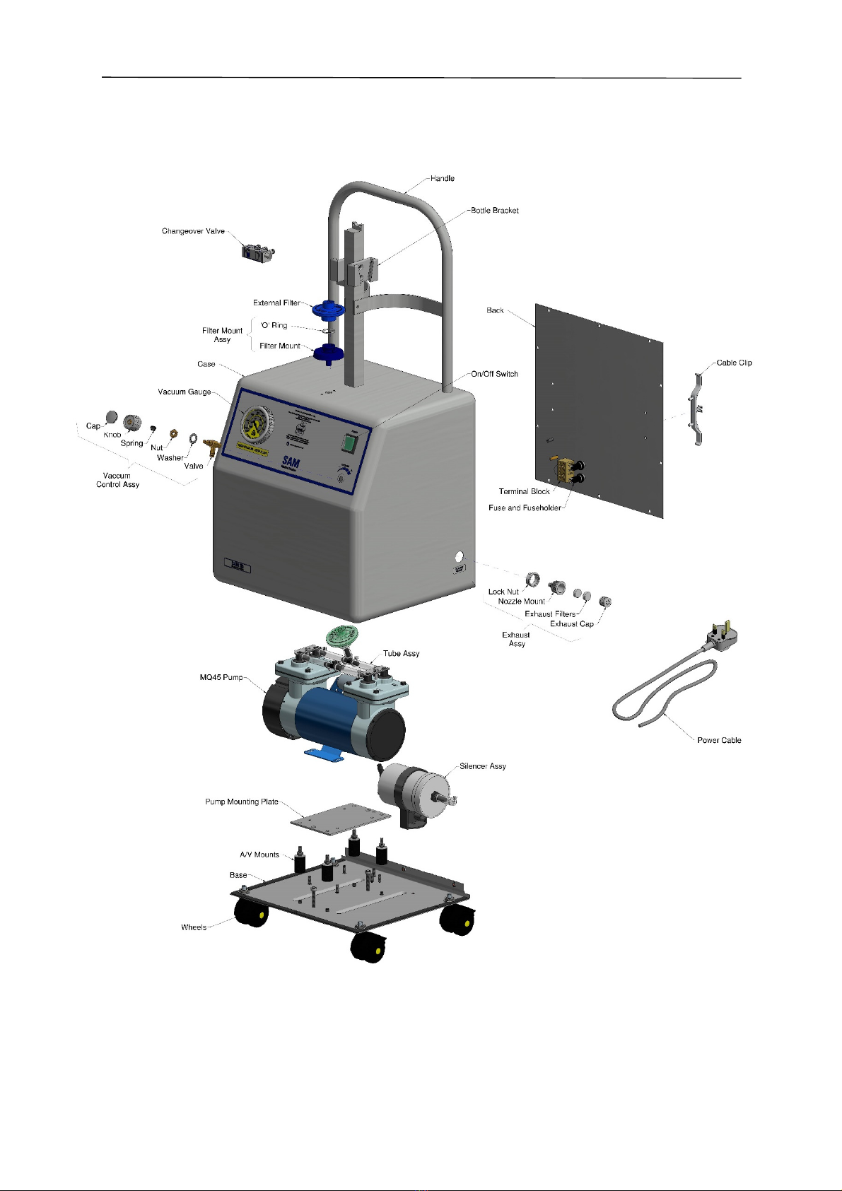
Vacuum Gauge
Vacuum Control
ON/OFF Switch
External Filter
Connection to
Collection Vessel
Collection Vessel
Bracket
Changeover
Valve

SA 35 and SA 36
Operation and Maintenance Manual
Manual 118 Issue 15
Page 7 of 28
3. INSTRUCTIONS FOR USE
3.1 Before Operating Unit
BEFORE operating your new SA suction unit please read the following instructions carefully.
Become thoroughly familiar with the operation and maintenance of the unit before using and note the
information on the control panel and rear of the unit. Only persons trained in its use should operate
the unit.
Check that the voltage supply is as printed on the rating plate fitted to the back of the SA suction
unit.
Unscrew and remove the transport screws located on the underside of the unit.
Warning! Always electrically isolate the SA suction unit from the mains power supply
before carrying out any cleaning, maintenance or repairs. Electrical isolation of
the SA suction unit is by removal of the mains power plug from the mains
power supply.
3.2 Unit Set Up
•Connect the desired collection system securely in place on the bracket fitted to the top of
the unit. More detail can be found later in this section.
•Connect the desired equipment to the patient inlet tube on the collection container top.
Multi-fit bubble tubing (If supplied) has an I/D ∅7mm. Recommended length of tubing
used is 2 meters.
•Connect the unit to the power supply, check label on rear of unit for correct ratings. Do
not obstruct access to the mains power supply, and ensure the power cable does not
create a trip hazard or is subject to damage. Ensure the exhaust outlet on the side of the
unit is kept clear of any restriction.
•Switch the SA suction unit on by pressing the green rocker switch so that it illuminates.
The lamp indicates the SA suction unit is operating and ready for use.
3.3 Handling
The larger SA suction unit are not normally intended for lifting or carrying. They will either be
designed to installed on a trolley or fitted with lockable wheels. This mobility allows the larger SA
suction unit to be moved during use and easily transported between locations.
3.4 Operating Environment
Operation of this equipment must be within the following ambient condition
+40°C
-5°C
%
80%
30%
Temperature Humidity
Warning! Never operate a SA suction unit in the presence of flammable gas such as
anaesthetic agents. This is an Explosion hazard!
3.5 Gauge (Manometer) - Indicated Vacuum
The unit has a gauge fitted to allow the vacuum to be set at a pre-determined level and monitored
during use. To achieve the desired degree of vacuum, occlude the tubing fitted to the patient inlet on
the collection container top, and read the indicated vacuum on the gauge. Adjust the vacuum control
until the required degree of vacuum is achieved. (Turning the knob clockwise
increases the
vacuum). The SA suction unit is now set to operate at the selected vacuum.
SA 35 and SA 36
Operation and Maintenance Manual
Manual 118 Issue 15
Page 8 of 28
3.6 External Filter
Warning! Never operate a SA suction unit without a MGE filter capsule.
The filter capsules are a sealed disposable bacterial or hydrophobic filter capsule. Both the bacterial
and hydrophobic filters have bacterial retention of 99.9999% ensuring safety and hygiene for patient
and operator. The 0.3 micron particle retention of the filter medium also gives not less than 99.985%
Dispersed Oil Particulate (D.O.P.) and so provides an effective barrier against possible aerosol
contamination. The hydrophobic filter also has an integrated micro porous membrane on the rear of
the filter medium which allows a clear flow of air through one way and an excellent block against any
accidental back flow the other. The external filters are fitted between the vacuum connector and the
filter capsule mount, and can be either a bacterial or hydrophobic filter. The connector, mount, and ‘O’
rings are autoclavable. However, the filter capsules are ‘Single Patient Use’ and must not be
autoclaved. The external filter must be changed with every patient and renewed in accordance with
the recommendations detailed in the ‘Daily Procedures’.
Warning! The filter capsules are single patient use and cannot be reused. Reuse of such
devices can be dangerous for both patient and operator.
3.7 Internal Filter
The SA suction unit must have fitted internally a hydrophobic filter capsule to prevent ingress of
foreign material into the pump. The hydrophobic filter prevents costly pump damage as well as
additional protection against contamination from liquids being sucked through due to jar overfill.
Liquid sucked through to the pump motor will cause damage and invalidate the warranty. The filter is
disposable and must not be autoclaved, but renewed in accordance with the recommended
maintenance program.
Warning! A hydrophobic filter must be fitted internally to prevent liquid passing through to
the pump. Hydrophobic filters only work once and should be replaced
immediately it becomes wetted.
3.8 Fluid Collection Containers
The silicon service tube (∅6mm I/D with 3mm minimum wall thickness) must be connected between
the filter and the changeover valve. The changeover valve must then be connected to the vacuum
port on the collection container. These tubes have an elbow connector on one end for fitting to the
filter and for fitting to the ‘VACUUM’ port of the SA 2 collection container. The silicon tubing used in
conjunction with this equipment is a replaceable item. It should be changed regularly according to the
level of usage and where it has become in any way contaminated or damaged.
Warning! All collection containers must be securely mounted when in use.
An anti-foam agent may be put into the fluid collection container, without disinfectant solution, before
use to reduce the possibility of frothing. It should not however, be placed into the container for
extended storage periods.

SA 35 and SA 36
Operation and Maintenance Manual
Manual 118 Issue 15
Page 9 of 28
3.8.1 SAM 2 Collection System
The SA 2 collection container is fitted as standard to all SA suction units. They are fully
autoclavable Polyester Carbonate (P.E.C.) collection containers, with integral handle and for IU
applications, with a wide bore. The collection containers are connected to the SA suction unit via a
changeover valve.
•Place the collection containers in the
brackets. Connect the tubing from the
changeover valve to the angle connector in the
centre of the lid.
•Connect the patient tube to the patient
connection.
•Turn on the SA suction unit.
•Check the desired vacuum is established.
•After the suction procedure – disconnect the
patient tube.
The SA 2 is fitted with an overflow valve designed to shut off the vacuum to the SA 2 collection
container when the fluid level reaches 1750ml. When the valve operates, the SA suction unit must
be switched off and the full container replaced by an empty one.
It should be noted that even after the valve has shut off, fluid might continue to be drawn into the
container to an extent dependent upon the level of vacuum in the container at the time when the valve
closes.
Warning! The overflow valve may not operate fully against frothing. To reduce frothing
an anti-foam agent may be used.
Warning! When replacing a full collection container, be aware of its weight and ensure
handling the collection container is comfortable to avoid the possibility of
spillage. Transport of the SA suction unit with a full jar attached is not
advised.
3.8.2 SAM 4 Collection System
The SA 4 collection container is fitted as standard to all SA suction units. They are fully
autoclavable Polyester Carbonate (P.E.C.) collection containers. The collection containers are
connected to the SA suction unit via a changeover valve.
•Place the collection containers in the
cradle. Connect the tubing from the
changeover valve to the connector on top
of the lid (marked ‘VACUUM’).
•Connect the patient tube to the ‘PATIENT’ connection.
•Turn on the SA suction unit.
•Check the desired vacuum is established.
•After the suction procedure – disconnect the patient tube
The SAM 4 is fitted with an integral shut off for overflow protection.
Warning! The overflow valve may not operate fully against frothing. To reduce frothing
an anti-foam agent may be used.
Filter
Elbow
Connector
Patient
Connection
Patient
Connection
Filter
Vacuum
Connection

SA 35 and SA 36
Operation and Maintenance Manual
Manual 118 Issue 15
Page 10 of 28
Warning! When replacing a full collection container, be aware of its weight and ensure
handling the collection container is comfortable to avoid the possibility of
spillage. Transport of the SA suction unit with a full jar attached is not
advised.
3.9 Disposable Liner Systems
The SA suction units have been designed to accept various disposable liner systems. When fitted,
protection of the unit against overflow is entirely dependent upon the correct use of the appropriate
liner in accordance with the manufacturers’ instructions.
Warning! No liability can be accepted by MGE for units affected by the occurrence of
overflow when Disposable Liner Systems are being used.
3.9.1 VacSax suction system
•Place liner into collection container and push firmly.
•Push the taper connector on the vacuum tubing from the
suction controller into the vacuum port with a twisting
motion.
•Connect the patient tubing firmly to the patient port to
ensure a good fit.
•Turn on the SA suction unit.
•Confirm suction is present at the patient tube by occluding
the patient tube end.
•After the suction procedure – disconnect the patient tube and fit stopper located on rim
into the port.
•Turn OFF the SA suction unit and remove the liner for disposal.
The collection container may be sterilised by autoclaving at 121°C or by washing with water based
disinfectants. Before autoclaving, rinse the collection container well to remove any detergent.
3.9.2 Abbott Receptal Disposable Suction System
•Place the collection container in the
bracket making sure that the tee
connection on the collection container is
tight. Fully extend the liner, and place it
into the collection container. Make sure that the liner is
tightly secured in the collection container.
•The liner incorporates an internal shut off valve,
which protects the vacuum source from
contamination. Connect the vacuum source tubing
(from the filter) to one side of the tee connection and
the lid to the other side using the ‘yellow to yellow’
coding.
•Connect the patient tube to the patient connection, either directly or by using the optional
elbow piece, which prevents kinking of the patient tubing.
•Turn on the SA suction unit to inflate the liner and the collection container is now ready
for use.
•For maximum safety and to minimise the risk of contamination when dismantling, the fluid
level must not rise above the ‘DO NOT FILL ABOVE THIS LINE’ mark on the collection
container.
•At the end of the procedure, the SA suction unit should remain switched on while the
patient suction tubing is removed from the patient port and discarded.
•Disconnect the liner lid tubing from the tee connection and immediately reconnect the
yellow connector to the patient port with a push and twist motion.
Tee Connection
Yellow to Yellow
Patient
Connection
Filter

SA 35 and SA 36
Operation and Maintenance Manual
Manual 118 Issue 15
Page 11 of 28
•Turn the vacuum off and use the thumb tab to remove the liner for disposal.
Warning! The liner lid tubing must not be used as a carry handle.
3.9.3 Serres Suction Bag System
•The system comprises the suction bag (A), the collection
container (B), and the angle connector (C).
•Place the collection container (B) in the bracket. Connect
the tubing from the SA filter to the angle connector (C).
•Place the suction bag into the collection container ensuring
bag tail is not trapped between the lid and collection
container.
•Turn on the SA suction unit.
•Install the suction bag by using the vacuum – Occlude the patient connection and
simultaneously press lightly from the middle of the lid.
•Establish the desired vacuum and ensure the bag is fully inflated.
•Connect the patient tube to the patient connection.
•After the suction procedure – disconnect the patient tube and close the connection with
the plug provided on the lid.
•Turn OFF the SA suction unit and remove the liner for disposal.
If necessary, the collection container only, may be washed (85°C) and autoclaved (121°C). Before
washing, disconnect the angle connector. If autoclaving, rinse the collection container well to remove
any detergent.
3.10 Effect of altitude
Altitude effects all vacuum pumps and it should be noted that there will be a reduction in the maximum
achievable vacuum / negative pressure level equivalent to approximately 3.5% per 300m
(approximately 1000ft) rise in altitude.
3.11 Cleaning Procedure
Warning! Contamination may be present on any components. When cleaning or
replacing any part of the SA suction unit appropriate protective clothing and
gloves MUST be worn to avoid contamination. Disposal of contaminated parts
must be according to local protocols.
Warning! Always electrically isolate the SA suction unit from the mains power supply
before carrying out any cleaning, maintenance or repairs. Electrical isolation of
the SA suction unit is by removal of the mains power cable from the mains
power supply.
Warning! Solvent-based cleaning agents or abrasive cleaners must not be used on any
SA suction units. Do not wash any SA suction units under running water or
submerge in water.
To clean the outside case of the SA suction unit, disconnect the unit from the power supply, wipe
over with a clean damp cloth or use an appropriate mild disinfectant solution. Following the
manufacturers’ instructions on cleaning product, and avoiding excessive moisture.
3.12 Transport
The SA suction unit will be adequately boxed and protected to ensure no damage occurs during
normal transportation of goods, providing the ambient conditions are within the following parameters:
Temperature max +60°C min -20°C Humidity max +80% min +30%
SA 35 and SA 36
Operation and Maintenance Manual
Manual 118 Issue 15
Page 12 of 28
-20°C
There are no restrictions for land, air, or sea transport.
3.13 Storage
SA suction units must be stored in a dry, dust-free, well ventilated environment. The storage
environment should not exceed the temperature and humidity conditions stated below. Avoid direct
sun or UV exposure and shield nearby sources of heat. The equipment should be stored in its original
packaging providing no damage is evident. Protect against ground moisture by storing on a shelf or
wooden pallet.
Temperature max +60°C min -20°C Humidity max +80% min +30%
-20°C
3.14 Long Term Storage
When the units are held in storage, or used very infrequently, the three-monthly maintenance period
may be extended to twelve months. Particular care must be taken when inspecting flexible
components, such as valves, diaphragms, to ensure embrittlement has not occurred.
SA suction units should be stored in a cool, dry environment, as stated above.
3.15 Instructions by Medical Staff to Patients
When the equipment is required by a patient for home use, Medical Staff must fully instruct the patient
on the safe operation of the equipment. In the event of equipment contamination or failure, the patient
must be advised to switch off the unit and contact the authority from which the unit is loaned.
3.16 Troubleshooting
Problem: Cause: Solution:
No power to unit
Unit not turned on Turn Main Switch „ON/OFF” ON
Wrong operating voltage Check mains voltage output
Mains not connected Connect mains cable
Defective Fuse Check fuse and replace if
indicated
Pumps fail to run Leak in vacuum system Check all connection and tubing.
Collection Jar is full Replace Jar
Pump suction power too weak
Vacuum leaks Check all seals and hoses. Make
sure Lid is securely on Jar.
Vacuum not to required setting
Turn vacuum control clockwise
until the desired suction power is
reached
Tubing is plugged, bent and/or
disconnected
Replace tubing if plugged and
eliminate any bends
Internal hydrophobic filter is
blocked or wet
Replace internal hydrophobic
filter. – Must be done by EBME
External filter is blocked Replace External filter.
If a problem cannot be solved, contact a fully trained and qualified engineer (EBME), authorized MGE
dealer or MGE (sales@mgelectric.co.uk).

SA 35 and SA 36
Operation and Maintenance Manual
Manual 118 Issue 15
Page 13 of 28
4. MAINTENANCE
Warning! Other than for routine daily procedures, any maintenance or repairs to MGE
products must be carried out by fully trained and qualified engineers (EBME) or
an authorized MGE dealer. Such persons must be familiar with the relevant
standards, rules, accident prevention regulations, and operating conditions as a
result of their training, experience, and instruction. They are qualified to carry
out the required activities and in so doing recognize and avoid potential
hazards. All testing on SA suction units should be in accordance with ISO
10079-1
Warning! No modification of this equipment is allowed.
Warning! Contamination may be present on any components. When cleaning or
replacing any part of the SA suction unit appropriate protective clothing and
gloves MUST be worn to avoid contamination. Disposal of contaminated parts
must be according to local protocols.
Warning! Any dismantling and re-assembly of this equipment - for whatever purpose -
must be followed by testing in accordance with the manufacturers’
recommendations as specified for Monthly maintenance.
Warning! Isolate the SA suction unit from the mains power supply before carrying out
any maintenance or repairs. Electrical isolation of the SA suction unit is by
removal of the mains power cable from the mains power supply.
4.1 Daily Procedures
•The external filter capsule should be changed after any of the following:
oEach day’s use.
oIf it becomes wetted by froth.
oAfter aspiration of any infective material.
oBefore being used on a new patient.
•Examine the collection container for damage. Replace if necessary.
•Examine the external tubing for ageing, damage, or contamination. Replace if necessary
using equivalent tubing (∅6mm I/D with 3mm minimum wall thickness).
Elbow connector
External Filter
Filter Mount
External tubing

SA 35 and SA 36
Operation and Maintenance Manual
Manual 118 Issue 15
Page 14 of 28
4.2 Monthly Maintenance
•Carry out the daily maintenance procedure.
•Check the vacuum and the flow at the collection container top.
•With the collection container empty and the vacuum control valve set to maximum, switch
on the unit and read the indicated vacuum on the gauge. Occlude the suction inlet
(Patient connection) on the collection container top and note the time taken for the gauge
to indicate an increase to 450mm Hg (60 kPa) vacuum. This time should not exceed 10
seconds.
•The gauge should continue to rise and stabilise to indicate the maximum vacuum
available, and this should be not less than 590mm Hg (78.7 kPa).
•Replace the exhaust filters in the exhaust outlet housing located on the side of the casing
and marked ‘Exhaust Outlet’.
4.3 Three Monthly Maintenance
•Carry out the monthly procedure. Poor performance of the unit would indicate the internal
pump requires maintenance
Warning! Always electrically isolate the SA suction unit from the mains power supply
before carrying out any cleaning, maintenance or repairs. Electrical isolation of
the SA suction unit is by removal of the mains power cable from the mains
power supply.
•Remove the back cover.
•Check the internal and external tubing for ageing or wear. Replace with equivalent tubing
where necessary. Tubing to gauge ∅5mm I/D, wall thickness min 2mm, all other tubing
on the SA suction unit ∅6mm I/D, wall thickness min 3mm.
•Replace the internal hydrophobic filter. Details in section 4.6 Replacing the Internal
Hydrophobic Filter
•Check the internal wiring for ageing or wear. Replace with equivalent material and
terminations where necessary.
•Examine the mains cable for wear or damage and replace if necessary using equivalent
cable.
•Replace the back cover. Do not overtighten the rear cover fixings. (Recommended
torque 20 cNm)
•Examine the overflow valve float mechanism (SA 2) to ensure that this has free
movement.
•Check the vacuum and flow performance at the collection container as previously
described
SA 35 and SA 36
Operation and Maintenance Manual
Manual 118 Issue 15
Page 15 of 28
4.4 General Layout

SA 35 and SA 36
Operation and Maintenance Manual
Manual 118 Issue 15
Page 16 of 28
4.5 Pump (If Required)
•Remove the pump from the SA suction unit.
•Remove the pump head from the pump casing and examine the diaphragm for signs of
wear.
•Check the balance within the connecting rod for excessive movement. Replace the
connecting rod and balance if necessary.
•Remove both pump head nozzles from the pump head.
•Remove the transfer valves.
•Clean the valve seats and check the valves for signs of wear.
•Replace any worn or damaged components as necessary and re-assemble.
•Replace the pump back into the SA suction unit and re-connect the internal tubing.
Note: Replacement kits are available to change an old LQ45 Pump with a new MQ24 Pump. Details
found in Options and Recommended Spares section.
MQ45 Pump Complete
230V 50/60Hz
Seal
Pump Head
Connector
Con Rod /
Diaphragm
Assembly

SA 35 and SA 36
Operation and Maintenance Manual
Manual 118 Issue 15
Page 17 of 28
4.6 Replacing the Internal Hydrophobic Filter
Warning! A hydrophobic filter must be fitted internally to prevent liquid passing through to
the pump. Hydrophobic filters only work once and should be replaced
immediately it becomes wetted.
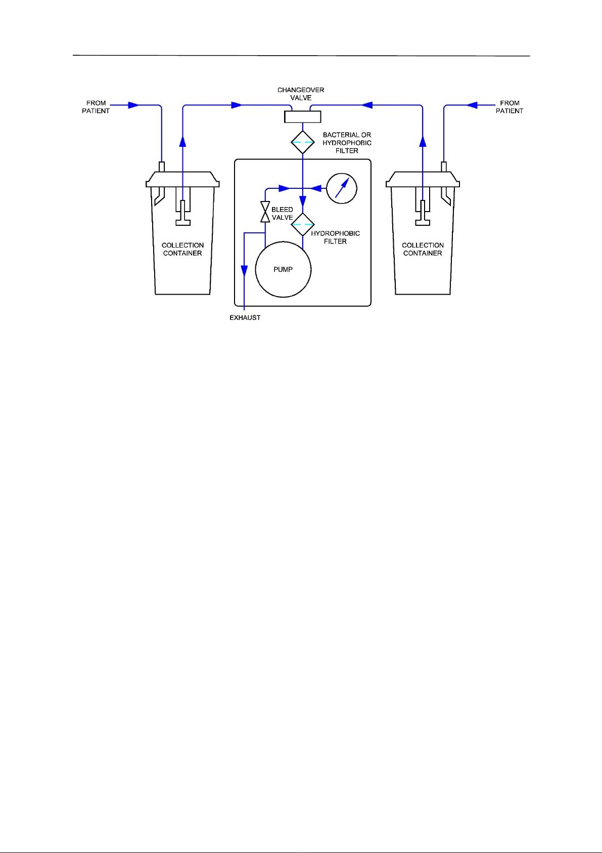
When replacing filters, particularly the hydrophobic filter, it is important to ensure the filter is connected
correctly to suit the direction of flow. The filters will only operate efficiently in one direction. The flow
diagram indicates the correct orientation installed in the pipework.
Hydrophobic Filter Installation
4.7 Replacing the Main Cable
Warning! Always electrically isolate the SA suction unit from the mains power supply
before carrying out any cleaning, maintenance or repairs. Electrical isolation of
the SA suction unit is by removal of the mains power cable from the mains
power supply.
•Isolate the SA suction unit from the mains power supply!
•Detach the back panel to access the internal terminal block.
•Disconnect the brown and blue conductors of the cable from the terminal block, and
withdraw the cable.
•Fit the replacement cable through the access hole.
•Connect the conductors to their respective terminals (Blue to Blue and Brown to Brown) in
the terminal block. Provide sufficient length of cable between the gland and terminal
block.
•Fit the cable into the labyrinth.
•Ensure all conductors are fitted as the original.
•Check continuity of each circuit.
•If reconnection is correct - replace the back panel.
Small Inlet
Gauge Side
Large Inlet
Pump side
SA 35 and SA 36
Operation and Maintenance Manual
Manual 118 Issue 15
Page 18 of 28
4.8 Flow Diagram
SA 35 and SA 36
SA 35 and SA 36
Operation and Maintenance Manual
Manual 118 Issue 15
Page 19 of 28
5. OPTIONS AND RECOMMENDED SPARES
5.1 Options
User Instruction Manuals are offered in English. Other languages are available on request.
SA
Model Electrical Specification Collection ars Power Cable Version
35 01 230Vac 50/60Hz 00 No ar 01 UK 01 Static
36 02 110Vac 50/60Hz 01 SA 2 (2Ltr) 05 European 02 Mobile
03 Abbott 06 Aus/NZ
04 Pennine
05 SA 4 (ltr)
06 VacSax
07 Serres
08 Cardinal
Medline
09 Cardinal CRD
10 SA 2 Holder
11 MTP
13 Flowmeter
Flovac
Example: SA 35 / 01 01 01 02
5.2 Recommended spares
Only original and approved spare parts must be used with all SA suction units – failure to use original
spares will invalidate the warranty and may cause injury and/or damage to unit.
All spares can be purchased by the user from MGE directly. Not all available spares are listed below.
It is recommended that only competent persons should undertake the replacement of spare parts.
5.2.1 Collection Container Components
Disposable bacterial filters – 24pk MSP1002
SA 2bottle SAM 2
SA 2IU bottle SAM 2 IU
SA 4bottle MSP1290
SA 4lt Jar Conversion MSP1317
SA 2bottle top assembly MSP1047
SA 2IU plastic bottle top assembly MSP1071
SA 2overflow valve – 10pk MSP1048
Silicone tube (O/D ∅12mm) – 25M MSP1156
SA patient multi-fit bubble tubing (I/D ∅7mm) – 30M MSP1155

SA 35 and SA 36
Operation and Maintenance Manual
Manual 118 Issue 15
Page 20 of 28
5.2.2 Unit Components
Disposable hydrophobic filters – 24pk MSP1003
Elbow connector and ‘o rings – 10pk MSP1004
Exhaust filter – 10pk MSP1015
Filter capsule mounts with ‘o’ rings and fixings – 10pk MSP1017
2amp 20mm fuses – 10pk MSP1225
Power cable – 2M MSP1567
5.2.3 Pump Components
MQ45 pump (Pump & motor 230V 50/60Hz) MSP1226
Motor 230V 50/60Hz MSP1227
MQ45 pump head connector set MSP1230
MQ45 pump head service kit MSP1229
MQ45 consumable spares service kit MSP1231
Con rod/diaphragm assembly MSP1210
SA 35 MQ45 replacement for LQ45 MSP1236
SA 36 MQ45 replacement for LQ45 MSP1240
5.2.4 Accessories
Foot-switch conversion kit MSP1151
This manual suits for next models
1
Table of contents
Other MGE UPS Systems Medical Equipment manuals


Popular Medical Equipment manuals by other brands


Barco
Barco CORONIS 1MP System manual

Portable Therapeutix
Portable Therapeutix SQUID Model One Instructions for use

Storz
Storz Rectal Speculum Instructions for use

MICROPOINT
MICROPOINT qLabs Data Manager installation guide

Integra
Integra MAYFIELD Head Clamp A2079 Instructions for use

Aether Biomedical
Aether Biomedical Zeus Instructions for use


