Micom Autodoor EDM MD-S Series User manual

EDM MD-S Series
Installation Manual
Page 1 of 23
MICOM AUTODOOR
Automatic Sliding Door Operator
Model: EDM MD-S
Original Instructions
INSTALLATION MANUAL
OSAKA –JAPAN
www.micomautodoor.com
REVISED DATE: MARCH 2018 No. MD0004

EDM MD-S Series
Installation Manual
Page 2 of 23
IMPORTANT SAFETY INSTRUCTIONS
•It is important for the safety of persons to follow these instructions. Save these instructions.
•Children being supervised not to play with the appliance.
•Frequently examine the installation for imbalance and signs of wear or damage to cables,
springs and mounting.
•Do not use if repair or adjustment is necessary.
•Disconnect the supply when cleaning or other maintenance.
•The installer is to check that the temperature range marked on the drive is suitable for the loca-
tion.
•Before installing the drive, check the driven part is in good mechanical condition, correctly bal-
anced and opens and closes properly.
•This drive is intended to be installed at a height of at least 2.5m above floor.
•WARNING: the drive shall be disconnected from its power source during cleaning, maintenance
and when replacing parts.
WARNING: Avoidance of Injury, Electric shock and Fire
•Safety Beam or Safety Curtain MUST be installed to ensure threshold safety.
•Installation and adjustment must be performed by approved personnel only.
•Repair and/or alteration to the control box and motor are prohibited.
•The power should be switched off during installation and service.
•Power supply of 200~240V AC only to used.
EDM MD-S Series
Installation Manual
Page 3 of 23
CAUTION: Avoidance of Injury and Malfunctions
•Do not switch off power supply whilst door(s) in motion.
•Ensure sliding door travel area is clear before switching power switch ON.
•Keep fingers, clothing & hair, clear of belt and all moving parts.
•Protective gloves should be worn when handling metal parts.
CAUTION: Avoidance of Injury during Maintenance & Disposal
•Risk of crushing or impact by a falling door panel or other solid object onto a person can
be avoided by laying any heavy object horizontally onto the floor, to one side of the
working area.
•Risk of slipping, tripping or falling can be avoided by placing any removed objects to one
side of the working area. A safe working area should be maintained by cordon or other
temporary boundary.
•Do not dispose of electrical appliances as unsorted municipal waste, use separate collec-
tion facilities.
•Contact your local government for information regarding the collection systems available.
•If electrical appliances are disposed of in landfills or dumps, hazardous substances can leak into
the groundwater and get into the food chain, damaging your health and well-being.

EDM MD-S Series
Installation Manual
Page 4 of 23
Contents
No.
Section
1
Product Description
1.1 Introduction
1.2 Delivery
2
EDM MD Series
2.1 Complete Operator Parts
3
Installation
3.1 Base Rail
3.2 Side View Drawing
3.3 EDM-MD Front View
3.4 Mounting Doors
3.5 Smooth Operation
3.6 Power On
4
Teaching / Learning
4.1 Teaching / Learning Operation
5
Set Up & Operation
5.1 Motor Gear Box
5.2 Control Box
6
Setting Table
6.1 Basic Setting Code
6.2 Hold Open Timer
6.3 Partial Open
6.4 Delay Function
7
Obstruction Detection
7.1 Closing Travel
7.2 Opening Travel
8
Basic Wiring
9
Specification
10
Optional Accessories
10.1 MICOM Function Selector Switch
10.2 Operation Modes
10.3 Wiring Drawing
11
E-Lock Wiring
12
Basic Setting Code Table –Cut out

EDM MD-S Series
Installation Manual
Page 5 of 23
1. Product Description
1.1 Introduction
EDM-MD Series is designed to provide a high quality yet economical automatic sliding door solution for easy open
and close operation whilst offering variable function adjustment of single or double door leaves up to 100kg per leaf.
Installation and set-up can be simply achieved in several steps. Door stroke is memorized by simply pushing the RE-
SET button one-time during initial installation or for servicing requirements.
Automatic operation is upon sensor or switch activation with safety beam threshold safety input active when the
door is in operation. Together with many other functions available, operational parameters can be adjusted to suit
each individual installation through an easily accessible visual LED display found on MD Control box face.
Easily accessible connections are located either as an independent terminal on the rail or by adding MICOM Sensor
and Battery Monitoring board (SMB) for EN16005 Compliance.
MICOM inbuilt safety features and quality components will ensure EDM-MD Series is safe, reliable and provides long
term service.
Main Features
•Economical & Cost Effective Sliding Door Solution
•Universal Power input 200-240VAC
•Door Capacity 100kg per leaf
•Door Speed 500mm/s
•Memorized one time door stroke
•Easily accessible Sensor and threshold safety Inputs
•Side Screen Safety Input
•Emergency Stop Signal Input
•Ratchet or Flip-Flop Function
•24V DC Power Output for Accessories
•Safe & Long Term Operation Guaranteed
•LED Digital Control Display
•Simple Door Parameter Setting
•Door Speed & Braking Adjustment
•Energy Saving (% Open) Function
•Delay Function for Electric Lock
•Wide Parameter Adjustments
•CE Compliant

EDM MD-S Series
Installation Manual
Page 6 of 23
1.2 Delivery
MICOM EDM-MD Series can be supplied in several formats as follows:
-Complete Operator consisting of: Base Rail, Cover, Control Box, Connection Harness, Motor Gear Box, Con-
nection Terminal, End Covers, Tooth Belt, Belt Bracket Link Assembly, Belt Connection Single & Double Door,
Belt Tightening / Idle Pulley Assembly, Hanger Roller Brackets x4 and Stopper x 2.
-Complete Operator - Standard Length:
Single Leaf - 2100mm
Double leaf - 4200mm
-FULL KIT –NOT ASSEMBED consisting of: Control Box, Connection Harness, Motor Gear Box, Connection Ter-
minal, End Covers, Tooth Belt (7M), Belt Bracket Link Assembly, Belt Connection Single & Double Door, Belt
Tightening / Idle Pulley Assembly, Hanger Roller Brackets x4 and stopper x 2.
-Rail & Cover Materials Only - Standard Length:
Single Leaf - 2100mm
Double leaf - 4200mm
-SHORT KIT (Retro-Fit YII- ZII/GII Rail UNDER DEVELOPMENT) consisting of: Control Box, Connection Har-
ness, Motor Gear Box Assembly, Connection Terminal and Belt Tightening / Idle Pulley Assembly (Without
Rail, Cover, End Covers, Tooth Belt or Hanger Roller Brackets).
Accessories
-Sensor / Threshold Safety - Microwave or Infrared detection sensors and safety beam products available.
-Function Selector Switch –4 Position Rotary switch available (Closed, Exit, Auto, Open & Emergency Exit Op-
tion)
-Door Profile Solutions –Various Fixed and Moving profile designs available without glass.
-Frameless Glass Brackets –Fitting Brackets for 10mm and 12mm Glass thickness available without glass.
-Floor Guides –Various floor guides for framed and frameless glass doors available.
For more information visit: www.micomautodoor.com or E-mail: info@micomautodoor.com

EDM MD-S Series
Installation Manual
Page 7 of 23
2. EDM MD-S Series
2.1 EDM MD-S Complete Operator Parts
No.
Description
1
Belt Tightening / Idle Pulley Bracket Assembly
2
Hanger Roller Bracket with Belt Bracket Link Assembly (Single Leaf)
3
Tooth Belt
4
Hanger Roller Bracket with Double Roller (Standard)
5
EDM MD Control Box
6
EDM MD Motor Gear Box Assembly
7
Door Stop
8
Motor Mount Bracket with Vibration Proof Rubber
9
Connection Terminal with Power On Off Switch
10
Base Rail with Side Cover (Cover not shown)
EDM MD-S Series
Installation Manual
Page 8 of 23
3. Installation
3.1 Base Rail Installation
CAUTION: Reduce risk of injury. Ensure installation area is clear of tripping hazards.
Ensure work area is clear of pedestrians and there is a restricted pedestrian access at all times dur-
ing works being carried out.
Positioning and Installing base rail:
-Refer to below EDM MD Drawing to find correct measurement of base rail position.
-Ensure hanger roller brackets are above level of entrance.
-Ensure floor clearance.
-Measuring from top of door profile, allow space for hanger roller bracket (as shown) plus floor clearance.
-Secure base rail with appropriate fixings.
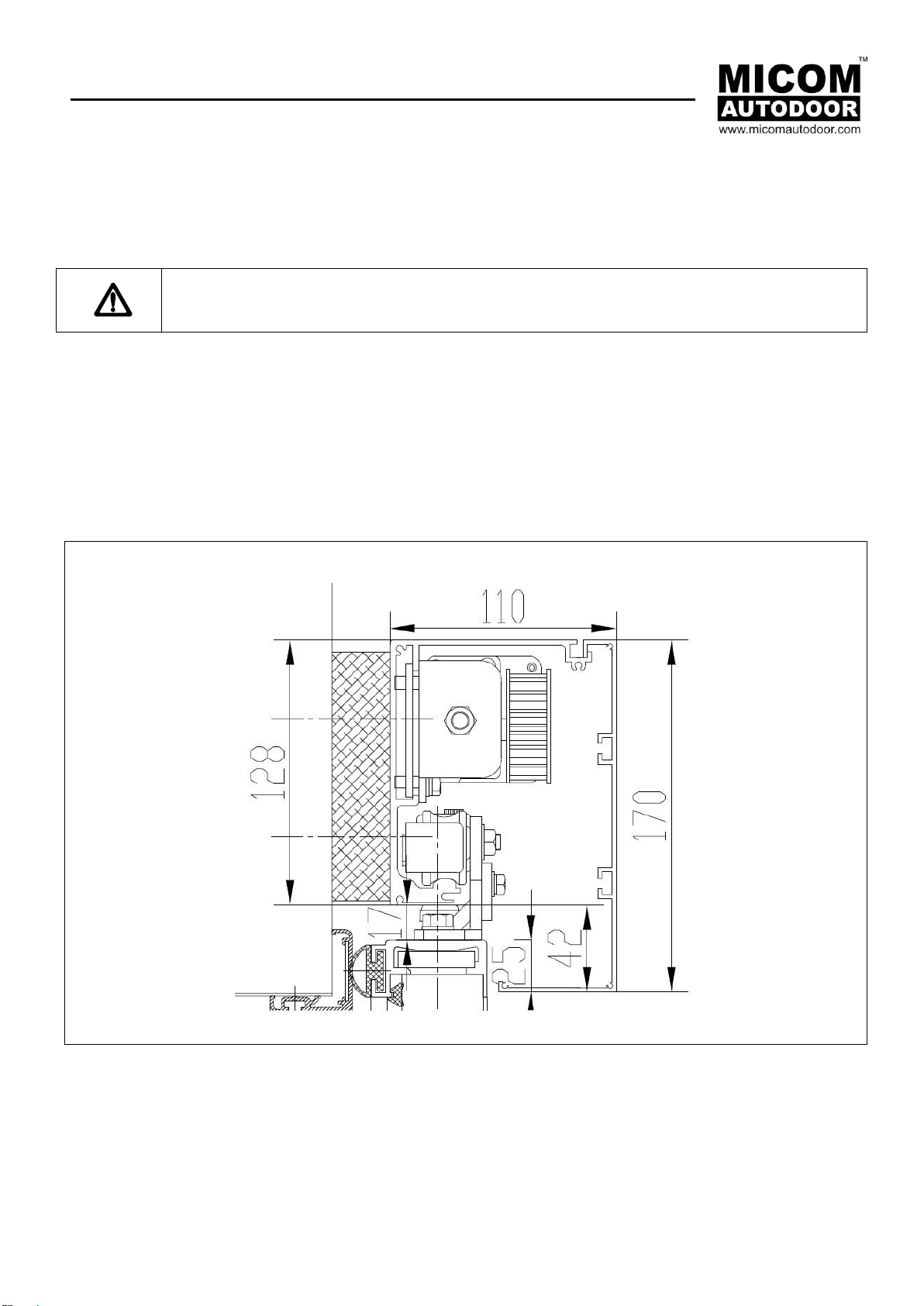
3.2 EDM MD-S –Side View Section
Measurement in mm

EDM MD-S Series
Installation Manual
Page 9 of 23
3.3 EDM-MD Front View

EDM MD-S Series
Installation Manual
Page 10 of 23
3.4 Mounting Doors
-Position hanger roller brackets on top of door leaf.
-Ensure hanger brackets are aligned, then secure in place.
-Loosen hanger bracket retainer to mount doors on rail.
-Mount doors on rail.
-Adjust and secure hanger bracket retainer 2mm from underside of base rail.
-Adjust door height for floor clearance.
-Check door alignment to eliminate gaps before tightening fully.
3.5 Smooth Operation
-Check opening and closing of door leaf with power off.
-Doors must run smoothly without friction or noise.
-Doors should be easy to push open and close.
-Check clearance from finished floor level (open & close).
3.6 Power On
Caution –Before switching the power on:
-Rail and doors are correctly installed
-Ensure tooth belt is tightened
-Main parts are correctly installed - Refer to wiring diagrams. Sec. 8.
The power switch is located to the right of motor fixed to the underside of the base rail.
4. Teaching / Learning Operation
CAUTION: Ensure that the door travel area is clear before pressing RESET in order to memorize
the door stroke.
4.1 Teaching / Learning
After installation is completed, in order to memorize the door stroke by a teaching or learning stoke. The following
steps are required.
-Set the slide switch (Prog / Run) down to “PROG”.
-Press and hold the “UP” button & “SET” button together. The RED and GREEN LED will flash once the RESET
is complete.
-Set the slide switch up to “RUN” and the door will start to close at low speed.
Starting from the fully closed position will ensure the doors are correctly optimised.
-From the fully closed position, the door/s will open at low speed.
Here EDM MD controller is memorizing the stroke by this cycle. Once at full open, the teaching / learning
stroke is complete. The door/s will then close at normal speed.
EDM MD-S Series
Installation Manual
Page 11 of 23
Note: Teaching data will be stored within the control unit, even if the main power is off. Once the mains power
is turned on, the stored data will be reloaded and door will continue its operation with need to re-learn it’s
stoke.
In case of a malfunction or in the event that the stored data is affected by electric noise during its operation, the
controller can be recovered by another RESET
We recommend taking a note of the Parameter settings before RESET is made.
5. Set Up & Operation
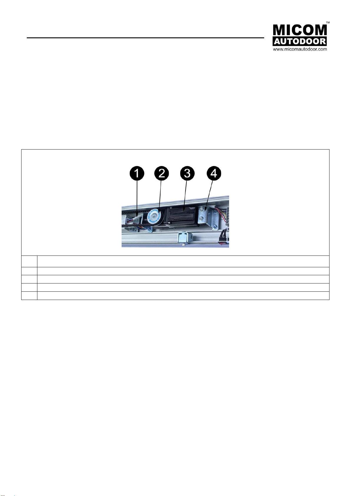
5.1 Motor Gear Box Assembly EDM MD-S
No.
Description
1
Connection Harness to EDM MD Control Box
2
Motor pulley
3
Brushless DC Motor
4
Motor Mount Base with Vibration Proof Rubber
EDM MD-S Series
Installation Manual
Page 12 of 23
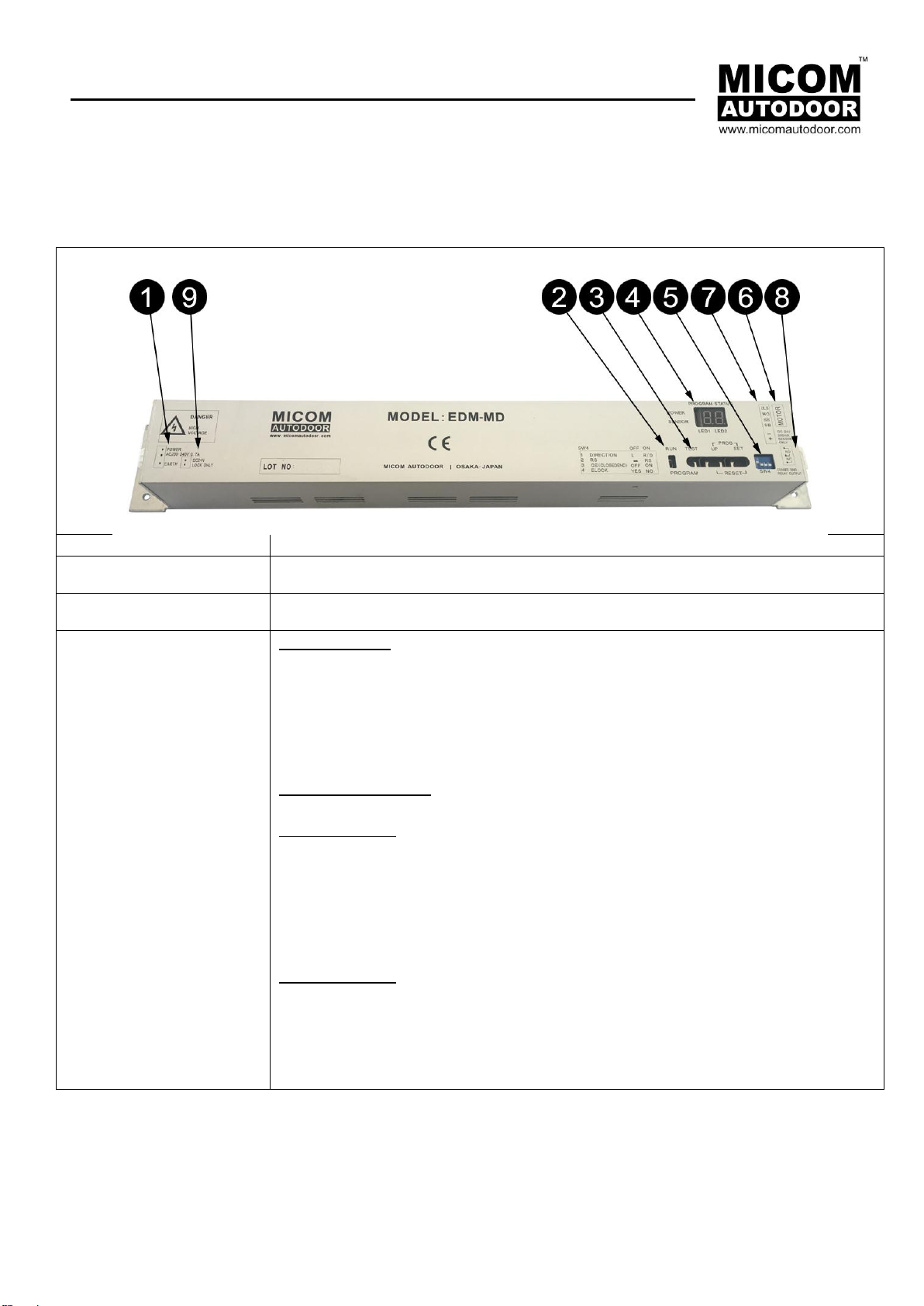
5.2 Control Box Assembly EDM MD
No.
1.
Power Input Plug in 200~240VAC
2. RUN/PRG switch
Slide switch to change from RUN mode to PROGRAM mode
3. TEST / UP & SET Buttons
RUN Mode Only
TEST Button –Used to check the basic function of the operator when servicing or in-
stallation. Activation signal for Test open cycle.
UP & SET Button –Used when in PROGRAM mode only. (To entre Programming
mode: Slide switch from RUN to PROG.)
PROGRAM Mode only
<How to RESET>
UP SET
ON ON : Hold both buttons to RESET. Set to “RUN”, then teaching starts.
UP & SET Button –Push and Hold together. After releasing buttons, LED shows open
counter. “OP ** ** ** **” (8 Digits).
<How to change setting>
UP SET
ON OFF : Change LED 1 value
OFF ON : LED 2 flash
ON OFF : Change LED 2 value
OFF ON : Value is fixed (LED 1/2 lights are on)
(Repeat this to change setting)

EDM MD-S Series
Installation Manual
Page 13 of 23
4. LED Display
LED Display is a visual display for the installer in order to correctly set up and operate
MICOM EDM MD Operator.
LED DISPLAY:
LED1 : Function / Application
LED2 : Parameter Value
Green LED : Power indicator
Red LED : Sensor indicator (SS or SB)
‘RUN’ Mode
When in ‘RUN’ mode, the operator will run as normal. LED display will show:
a. Number of open cycles. (Memory is cleared by main-power off).
b. Error indication
Error Code:
E0 : Door travel distance during teaching cycle is too short (less than 150mm).
E1 : Open error (Obstruction during the opening cycle)
E2 : Closer error (Obstruction during the closing cycle)
E4 : Loose belt (Longer stroke than stored data)
E6 : E-lock error (no un-lock signal input)
‘PROGRAM’ Mode
When in PROGRAM mode, changes to operational parameter values can be made.
(To entre Programming mode: Slide switch from RUN to PROG.)
See setting table. Sec 6.
5.SW4
Note : After changing setting of SW4, turn the main power OFF/ON to save the ad-
justment.
SW1 : Opening direction
SW2 : RS function (Ratchet or Flip Flop)
SW3 : Close pressing –Set ON if the motor generates vibration at the closed position.
Closing Press function will be cut off 2-3 sec after fully closed. Otherwise Close Press is
always on.
Set OFF –Always closing press at closed position.
SW4 : E-lock (set OFF when E-lock is connected (YES)
6.Motor Plug
Connection of Motor to Control by Plug in
7. Sensor Harness
Connection of Sensor Harness to Control by Plug in
8. E-Lock
Relay Output (NO or NC) (DC24V 300mA)
9. DC 24V
Output for E-Lock (Can also be used for Sensors/ Accessories) (DC 24V 300mA)

EDM MD-S Series
Installation Manual
Page 14 of 23
6. Setting
6.1 Basic Setting Code (Set the slide switch to PROGRAM)
Code
Function
Volume
Factory
setting
Remarks
LED1
LED2
0
Hold Open Time
1~F
1
1-9sec, A:10sec, B:20sec, C:30sec, D:40sec, E:50sec F:60sec.
1
Open High
Speed
0~A
7
Setting of open high speed
2
Open Low Speed
0~A
4
Setting of open low speed
3
Open Break
Force
0~A
5
Setting of open break force
4
Open Force
0~A
5
Setting of open motor torque
5
Close High
Speed
0~A
5
Setting of close high speed
6
Close Low Speed
0~A
4
Setting of close low speed
7
Close Break
Force
0~A
5
Setting of close break force
8
Close Force
0~A
3
Setting of close motor torque
9
Partial Open
Width
0~3
1
Partial open is available by HO signal.
0:35%, 1:50%, 2:65%, 3:80%
A
Open Delay (*)
0~3
1
0 : No delay time after un-lock signal is confirmed.
1/2/3 : Below delay time from SS is activated to door starts to
open.
< 1:0.1sec, 2:0.5sec, 3:1.0 sec.>
When set 1/2/3/, door opens regardless of whether unlock sig-
nal.
If E-Lock can output unlock signal, it must be set "0".
B
Mode Switching
0~2
0
0 : HO (Half Open)
1 : AS (Side Screen Safety)
2 : ES (Emergency Stop)
(*) :
This function is available when SW4-4 is set OFF
When SW-4 is set ON, door starts to open upon SS without delay.

EDM MD-S Series
Installation Manual
Page 15 of 23
6.2 Hold Open Time
Value
1
2
3
4
5
6
7
8
9
A
B
C
D
E
F
Open
Time
(sec.)
1
2
3
4
5
6
7
8
9
10
20
30
40
50
60
6.3 Partial Open (Energy Saving) %
Value
0
1
2
3
Partial Open
35
50
65
80%
6.4 Open Delay (E-Lock)
Value
1
2
3
Time Delay (After Activation)
0.1 sec
0.5 sec
1.0 sec
7. Obstruction Detection
CAUTION: To avoid risk of injury to pedestrians, it is always recommended to install threshold
safety devices such as safety beams or types threshold protection.
In the even an object is placed in the threshold and not detected by safety devices; the following obstruction detec-
tion function will ensure safe operation as follows:
7.1 During closing travel
-On contact with object, doors will reverse at normal speed. After open time, door will close at low speed.
-Object is not cleared, door will stop and the controller shows E2 error.
-Object is cleared and doors continue to full closed. Here doors recover to normal status and await next acti-
vation signal.
7.2 During Opening travel
- On contact with object, door stops at the position and show E1 error.
- Recovery from E1 & E2 error:
The operator will recover automatically after 15sec.
Once the object is cleared, the door will recover automatically upon the next activation.

EDM MD-S Series
Installation Manual
Page 16 of 23
8. EDM MD Basic Wiring
9. Specification
Model
MD-S-S
MD-S-D
Application
Single
Double
Applicable door
(Max)
Weight
100kg
100kg x2
Dimension
W1500xH2500 (Max)
W1500xH2500 (Max)
DH/DW ratio
4.0
4.0
Open Door Speed
Adjustable 160 - 500mm/s (11 steps adjustable)
Close Door Speed
Adjustable 160 - 400mm/s (11 steps adjustable)
Power Consumption
200 -240V AC, 0.7A
Power Output
24V DC, 300mA
Motor
DC 24V / 55W Brushless
Braking Adjustment
0-A value (11 steps adjustable)
Door Open Timer
1-60sec (16 steps adjustable)
Partial Open (Winter/Summer)
35%, 50%, 65%, 80% (4 steps adjustable)
Safety Obstruction
Closing Travel: Safety Return / Opening Travel: Safety
Stop
Operating Temperature & Humidity
0C –50C / 30% - 85%
EDM MD-S Series
Installation Manual
Page 17 of 23
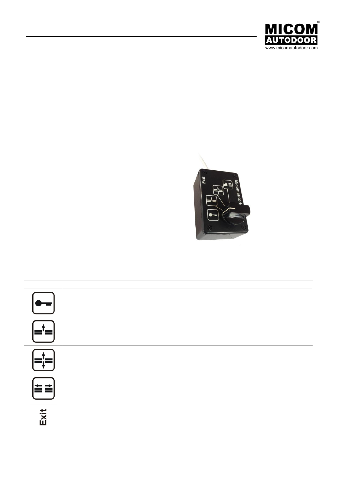
10. Optional Accessories
10.1 MICOM Function Selector Switches - 4 Positions with Rotary Knob
MICOM Function Selector Switches offer several options of door control. As either a rotary knob or with a secure
key, allows selection of 4 to 5 separate door modes. Economic in design, MICOM Function Selectors are easy to in-
stall and operate. Supplied in a fire retardant black plastic mount box, with attractive cover design in white, our func-
tion selectors can be fitted to walls or aluminium frames alike.
10.2 Operation Modes
-1. Closed
-2. Exit Only
-3. Automatic
-4. Hold Open
-Push Button (Option)
-Complete with 3m Cable
Symbols
Description
Position 1. Closed / Night
Position 2. Exit Only (Entry Only available as additional option)
Position 3. Automatic
Position 4. Hold Open
Exit - Push Button (option) for in case ‘Closed / Night’ is selected.

EDM MD-S Series
Installation Manual
Page 18 of 23
10.3 MICOM Function Selector Switch - Wiring Drawing
4 Position with Rotary Knob - Available in 2 configurations
10.3.1 Rotary Function Selector Switch - 4 Position - Standard

EDM MD-S Series
Installation Manual
Page 19 of 23
10.3.2 Rotary Function Selector Switch - 4 Positions with Push Button –Emergency Exit (Option)

EDM MD-S Series
Installation Manual
Page 20 of 23
11. Electromagnetic Lock Wiring
This manual suits for next models
2
Table of contents
Other Micom Autodoor Gate Opener manuals


