Micro Detectors LS4 Series User manual

LS4 SAFETY LIGHT CURTAIN
CAT8ELS1251403 • 26/06/2018
1
English
LS4 SAFETY LIGHT CURTAIN
SUMMARY
!"#$%&'(#!%")******************************************************************************************************************************************)+!
,$!"(!,-.)%/)%,.$0#!%")*********************************************************************************************************************)1!
!"2#0--0#!%")********************************************************************************************************************************************)3!
,4567648689)**************************************************************************************************************************************************************):!
;<57=>?2@<A=),4567648689)**********************************************************************************************************************************)B!
(<@CD@<7648)4E)5<E=7F)G657<8C=)***************************************************************************************************************************)H!
;D@76I@=)5F57=J5)***************************************************************************************************************************************************)K!
'5=)4E)G=E@=C7689)J6>>4>5)*********************************************************************************************************************************)LM!
&657<8C=)E>4J)>=E@=C76A=)5D>E<C=5)*****************************************************************************************************************)LL!
;=CN<86C<@)<55=JO@F)<8G)4I76C<@)<@698J=87)********************************************************************************************)LP!
Q=>76C<@)I4567648689)4E)7N=)@69N7)CD>7<68)******************************************************************************************************)L+!
Models!with!14,!20mm!resolution!..............................................................................................................................!13!
Models!with!30,!40mm!resolution!..............................................................................................................................!13!
Models!with!50,!90mm!resolution!..............................................................................................................................!13!
Multibeam!Models!..............................................................................................................................................................!14!
R4>6S487<@)I4567648689)4E)7N=)@69N7)CD>7<68)************************************************************************************************)L1!
.@=C7>6C<@)C488=C76485)***************************************************************************************************************************************)L3!
Layout!of!the!connectors!on!MASTER/SLAVE!light!curtain!.............................................................................!15!
Emitter!connections!..........................................................................................................................................................!16!
Receiver!connections!........................................................................................................................................................!17!
Warnings!regarding!connection!cables!.....................................................................................................................!18!
(48E69D><7648)<8G)4I=><7689)J4G=5))T;<57=>);4G=@5)?)U67N)687=9><7=G)C487>4@)ED8C76485V)***)LK!
Automatic!operation!..........................................................................................................................................................!19!
Manual!operation!................................................................................................................................................................!19!
Connection!of!external!contactors!K1!and!K2!........................................................................................................!20!
Examples!of!connection!with!M.D.!safety!modules!..............................................................................................!21!
%,.$0#!%")0"&)#.(R"!(0-)&0#0)*************************************************************************************************)P1!
-69N7)5698<@5)*********************************************************************************************************************************************************)P1!
Emitter!light!signals!...........................................................................................................................................................!24!
Receiver!light!signals!.........................................................................................................................................................!24!
#.2#)ED8C7648)*******************************************************************************************************************************************************)P3!
27<7D5)4E)7N=)4D7ID75)******************************************************************************************************************************************)P3!
#=CN86C<@)5I=C6E6C<76485)***********************************************************************************************************************************)P:!
&6J=856485)***********************************************************************************************************************************************************)+L!
(R.(W%'#2)0"&);0!"#."0"(.)******************************************************************************************************)++!
/D8C7648<@)CN=CX5)***********************************************************************************************************************************************)++!
#>4DO@=5N447689)*************************************************************************************************************************************************)+1!
0CC=554>6=5?2I<>=5)********************************************************************************************************************************************)+:!
Y'0$0"#..)**********************************************************************************************************************************************)+B!

LS4 SAFETY LIGHT CURTAIN
2 CAT8ELS1251403 • 26/06/2018
English
ABBREVIATIONS AND SYMBOLS USED IN THIS MANUAL
FE = Functional earth (earth connection)
M/S = Master/Slave System
OSSD = Output Signal Switching Device = Light curtain’s solid state safety outputs
TX = Safety light curtain emitter.
RX = Safety light curtain receiver.
Hand protection light curtains
Arm and leg protection light curtains.
Full body protection light grids.
!This symbol indicates an important warning for personal safety. Failure to comply
with this warning may result in high level risk for exposed personnel.
èThis symbol indicates an important warning.

LS4 SAFETY LIGHT CURTAIN
CAT8ELS1251403 • 26/06/2018 3
English
INTRODUCTION
The LS4 light curtain is an optoelectronic safety device belonging to the category of Type 4 electro-
sensitive protective equipment for the protection of personnel exposed to risks inherent in the use
of hazardous machines or plants, complying with the
EN 61496-1 and IEC 61496-2 standards. The LS4 is available in three different versions:
1. LS4
Type 4 light curtain consisting of Emitter plus Receiver with automatic reset.
2. LS4 (With integrated control functions)
Type 4 light curtain consisting of Emitter plus Receiver with integration of additional functions
such as control of feedback from any external contactors and management of manual/automatic
operation.
3. LS4 (MASTER/SLAVE)
Type 4 light curtain (with integrated control functions) comprising two (or three) TX/RX pairs
(connected in series), one of which comprising the MASTER light curtain (with integrated functions)
and one (or two) the SLAVE light curtain.
A set of indicator leds on the Emitter and Receiver provide the information needed for a correct
use of the device and for the assessment of any malfunction. The automatic fault sensing system
permits independent detection by the LS4 light curtain of any dangerous fault in a time equal to
the light curtain response time.
!For any safety problem, if necessary, consult the safety authorities of the country of
use or the competent industrial association.
!For applications in the food industry, consult the manufacturer to verify compatibility
of light curtain materials with the chemical agents used.
!The protection capability of optoelectronic safety devices is not effective in cases in
which:
- The machine stopping device cannot be actuated electrically and it is not possible
to stop all dangerous machine movements immediately and at any time during the
operating cycle.
- The hazardous condition is associated with the falling of objects from above or
ejection of these from the machine.
- Anomalous forms of light radiation are present (for example, use of cablelless
control devices on cranes, radiation from weld spatter, etc).
In this case additional measures may be necessary to ensure that the ESPE does
not fail to danger.
LS4 SAFETY LIGHT CURTAIN
4 CAT8ELS1251403 • 26/06/2018
English
PRINCIPLE OF OPERATION
If the protected area is clear, the two outputs on the Receiver are active and enable
the machine to which they are connected to operate normally.
Each time that an object bigger than or equal in size to the resolution of the
system intercepts the optical path of one or more beams, the Receiver deactivates
its own outputs. This condition enables hazardous machine movements to be
stopped (by means of an adequate machine emergency stop circuit).
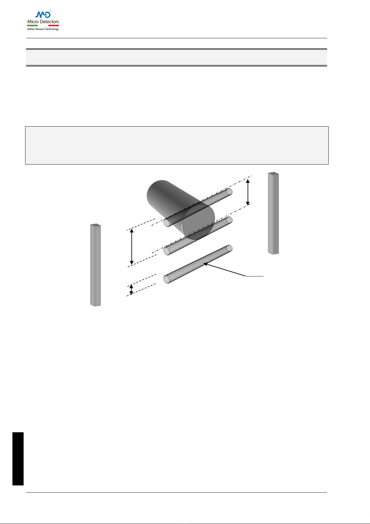
èResolution is the smallest sized object that, passing through the protected area,
interrupts at least one of the beams generated by the light curtain (Figure 1),
causing certain intervention of the device and consequent stopping of the
hazardous movement of the machine.
Figure 1 - Resolution
Resolution remains constant regardless of working conditions as it depends only on the geometric
characteristics of the mirrors and on the centre distance between two adjacent lenses.
The height of the protected area is the effective height protected by the safety light curtain. If
the curtain is positioned horizontally, this value indicates the depth of the protected area.
The working range indicates how far the emitter and receiver can be separated and function
properly.
LS4 is available with the following resolutions:
•14mm (protected heights from 160mm to 1960mm): PROTECTION OF THE FINGERS.
•20mm (protected heights from 160mm to 1960mm): PROTECTION OF THE FINGERS.
•30mm (protected heights from 160mm to 2260mm): PROTECTION OF THE HANDS.
•40mm (protected heights from 310mm to 2260mm): PROTECTION OF THE HANDS.
•50mm and 90mm (protected heights from 310mm to 2260mm):
PROTECTION OF THE LIMBS.
The LS4 is also available in a Multibeam version with a distance between the
mirrors of:
•500mm (2 beams), 400mm (3 beams), 300mm (4 beams).
PROTECTION OF THE BODY.
P = Pitch between two lenses
D = Diameter of a lens
R = Resolution = P+D
P
R
D
Receiver
Emitter
Beam
LS4 SAFETY LIGHT CURTAIN
CAT8ELS1251403 • 26/06/2018 5
English
INSTALLATION
Before installing the LS4 safety system, check all the conditions listed below:
!The level of protection of LS4 (Type 4, SIL3, SILCL3 PLe) must be compatible with the
level of danger of the system to be protected.
!The safety system is used only as a stopping device and not to control the machine.
!The machine movement is actuated electrically.
!All dangerous movements of the machine can be interrupted immediately. In
particular, the machine stopping times must be known and, if necessary, measured.
!The machine must not generate hazards due to projection or falling of materials
from above; otherwise, additional mechanical guarding must be provided.
!The smallest size object to be detected must be greater than or equal to the
resolution of the selected model.
Knowing the shape and dimensions of the dangerous area, it is possible to calculate the width and
height of the related access area :
!Compare these dimensions with the maximum working range and the height of the
protected area of the model used.
Before positioning the safety device, comply with the following general indications:
!Check that the temperature of the environment in which the system is installed is
compatible with the operating temperature parameters indicated on the product label
and in the technical data.
!Do not position the Emitter and the Receiver close to very bright or flashing sources
of light.
!Particular operating conditions may affect the sensing level of photo-electric devices.
In environments characterised by fog, rain, fumes or dust, to always guarantee
correct operation of the appliance, it is advisable to apply suitable correction factors
Cf so as to maximum working range values. In these cases:
where Pu and Pm are, respectively, the working and maximum range expressed in
metres.
The recommended correction factors CF are indicated in the table below.
OPERATING CONDITIONS
CORRECTION FACTOR Cf
Fog
0.25
Vapours
0.50
Dust
0.50
Dense fumes
0.25
Table 1 – CF correction factors
!If the device is installed in environments characterised by sudden changes in
temperature, suitable precautions must be taken to prevent the formation of
condensation on the mirrors, which could impair detection capability.
Pu = Pm x Cf

LS4 SAFETY LIGHT CURTAIN
6 CAT8ELS1251403 • 26/06/2018
English
Positioning
The Emitter LS4Eand the Receiver LS4Rmust be positioned so that it is
impossible to access the dangerous area from above, from below and from the
sides without intercepting one of the beams. Useful indications for correct
positioning of the light curtain are provided in the figure below.
Incorrect positioning of the light curtain
Correct positioning of the light curtain
Figure 2- Positioning

LS4 SAFETY LIGHT CURTAIN
CAT8ELS1251403 • 26/06/2018 7
English
Master/Slave Positioning
In addition to standard models (that can be positioned either horizontally or vertically), LS4 can
be purchased in a MASTER/SLAVE configuration. This configuration comprises two (or three) pairs
of light curtains in which the two (or three) Emitters and the two (or three) Receivers are connected
in series.
Figure 3 – Examples of Master/Slave configurations
The connection cable between the master and slave may be up to 50 metres in length. This
characteristic permits configuration of an application with two light curtains positioned one at the
front and one at the rear of the dangerous machine, with a single connection towards the machine
power and control circuits (Figure 4).
Figure 4 - Example of Master/Slave application with mechanical guards
MASTER
MASTER
SLAVE
SLAVE2
SLAVE

LS4 SAFETY LIGHT CURTAIN
8 CAT8ELS1251403 • 26/06/2018
English
Calculation of safety distance
The light curtain must be positioned at a distance equal to or greater than the minimum safety
distance Sso that the dangerous point can be reached only after stopping the dangerous
movement of the machine (Figure 5).
According to the EN13855:2010 European standards, the minimum safety distance Smust be
calculated using the following formula :
S = K (t1 + t2) + C
C = 8 (d-14)
where:
S
Minimum safety distance
mm
K
Operator approach speed to the dangerous area
mm/sec
t1
Total response time of the light curtain, in seconds
sec
t2
Response time of the machine in seconds, i.e. the time taken by
the machine to stop the dangerous movement from the moment
in which the stop signal is transmitted
sec
C
Additional distance that varies according to the application1
mm
d
Resolution
mm
Table 2 – Safety distance
!Failure to comply with the safety distance reduces or impairs the protection function
of the light curtain.
!If positioning of the light curtain does not prevent the operator from accessing the
dangerous zone without being detected, additional mechanical guards must be
installed.
Figure 5 – Safety distance S
1For further information on additional safety distance, refer to EN13855:2010.
DANGEROUS ZONE
LS4 SAFETY LIGHT CURTAIN
CAT8ELS1251403 • 26/06/2018 9
English
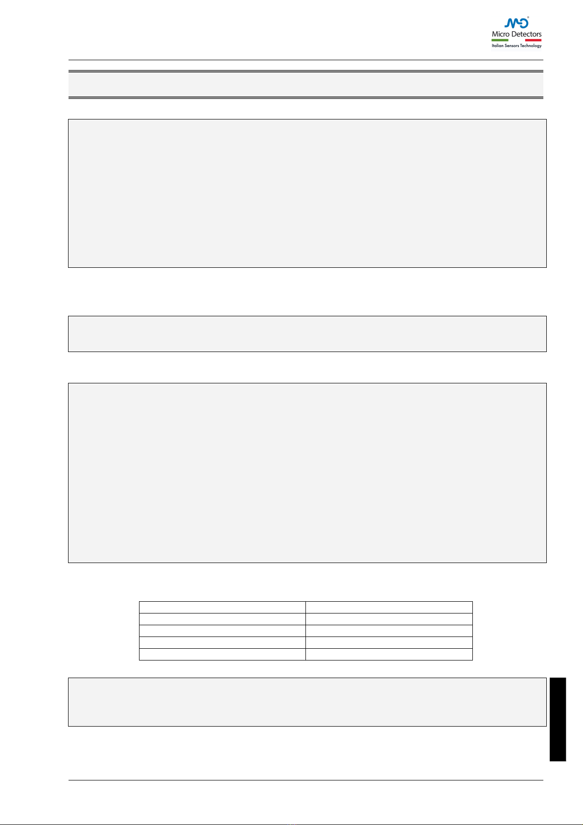
Multiple systems
When several LS4 are used, precautions must be taken to prevent optical interference between
these: position the elements so that the beam of the Emitter of one system is received only by its
respective Receiver.
Figure 6 provides examples of correct positioning of two photo-electric systems. Incorrect
positioning may cause interference, with possible malfunction of the system.
Figure 6 – Multiple systems
èThis precaution is not necessary in the case of MASTER/SLAVE systems.
Systems installed side by side: A
Adjacent positioning of the two emitters
Systems installed one above the other: B
“L” installation: C
Crossed positioning between emitters and
receivers

LS4 SAFETY LIGHT CURTAIN
10 CAT8ELS1251403 • 26/06/2018
English
Use of deflecting mirrors
For protection or control of areas accessible from several sides, one or more deflecting mirrors
can be used in addition to the Emitter and Receiver.
Deflecting mirrors make it possible to redirect the beams generated by the Emitter on several
sides.
Wishing to deflect the beams generated by the Emitter by 90°, the perpendicular to the surface of
the mirrors must form an angle of 45° with the direction of the beams.
An application in which two deflecting mirrors have been used for "U" shaped protection is
illustrated in the figure below.
Figure 7 – Deflecting mirrors
When using deflecting mirrors, comply with the following rules:
•Position the mirrors so as to comply with the minimum safety distance S
(Figure 7) on each side of access to the dangerous area.
•The working distance (working range) is given by the sum of the lengths of all the
access sides to the protected area. (Note that the maximum working range
between the Emitter and Receiver is reduced by 15% for each mirror used).
•In the installation phase, take care to avoid twisting along the longitudinal axis of
the mirror.
•Standing close to and in axis the Receiver, check that the entire shape of the
Emitter is visible on the first mirror.
•It is advisable not to use more than three deflecting mirrors.

LS4 SAFETY LIGHT CURTAIN
CAT8ELS1251403 • 26/06/2018 11
English
Distance from reflective surfaces
!The presence of reflective surfaces close to the light curtain may cause occasional
reflections that prevent sensing. Referring to Figure 8, object Ais not detected due
to surface Sthat, reflecting the beam, closes the optical path between the Emitter
and Receiver. Therefore, a minimum distance d must be maintained between any
reflecting surfaces and the guarded area. We recommend calculating the minimum
distance dusing the values for Type 4 devices as set forth in IEC/EN 61496-2.
Figure 8 - Reflective surfaces
In Figure 9these values are shown as a function of the distance lbetween the emitter and the
receiver.
Figure 9 - Minimum distance d
After installing the system, check for any reflective surface that intercept the beams, first of all at
the centre and then close to the Emitter and Receiver. During this procedure, the red led on the
Receiver must never switch off.
d
l

LS4 SAFETY LIGHT CURTAIN
12 CAT8ELS1251403 • 26/06/2018
English
Mechanical assembly and optical alignment
The Emitter and Receiver must be installed facing each other, at a distance equal to or less than
that indicated in the technical data. Using the provided inserts and fastening brackets, place the
Emitter and Receiver so that they are aligned and parallel to each other, and with the connectors
facing the same side.
Perfect alignment of the Emitter and Receiver is essential for efficient functioning of the light
curtain; this operation is facilitated observing the indicator leds of the Emitter and of Receiver.
Figure 10 – Mechanical assembly
Figure 11 – Optical alignment
•Position the optical axis of the first and last beam of the Emitter on the same axis
as that of the corresponding beams on the Receiver.
•Move the Emitter in order to locate the area within which the green led on the
Receiver remains on, then position the first beam of the Emitter (that close to the
indicator led) at the centre of this area.
•Using this beam as pivot, with minor movements of the opposite end, establish the
free protected area condition which, in this situation, will be indicated by lighting
up of the green led on the Receiver.
•Lock the Emitter and the Receiver in place.
During these operations it may be useful to check the presence of the blue led weak
signal (only for 14mm and H models) on the Receiver display. Upon completion of
alignment, this LED must be off.
èIf the Emitter and Receiver are installed in areas subject to strong vibrations, vibration-
damping supports must be used (for the order code, see the ACCESSORIES/SPARES
paragraph) so as not to impair operation of the circuits.

LS4 SAFETY LIGHT CURTAIN
CAT8ELS1251403 • 26/06/2018 13
English
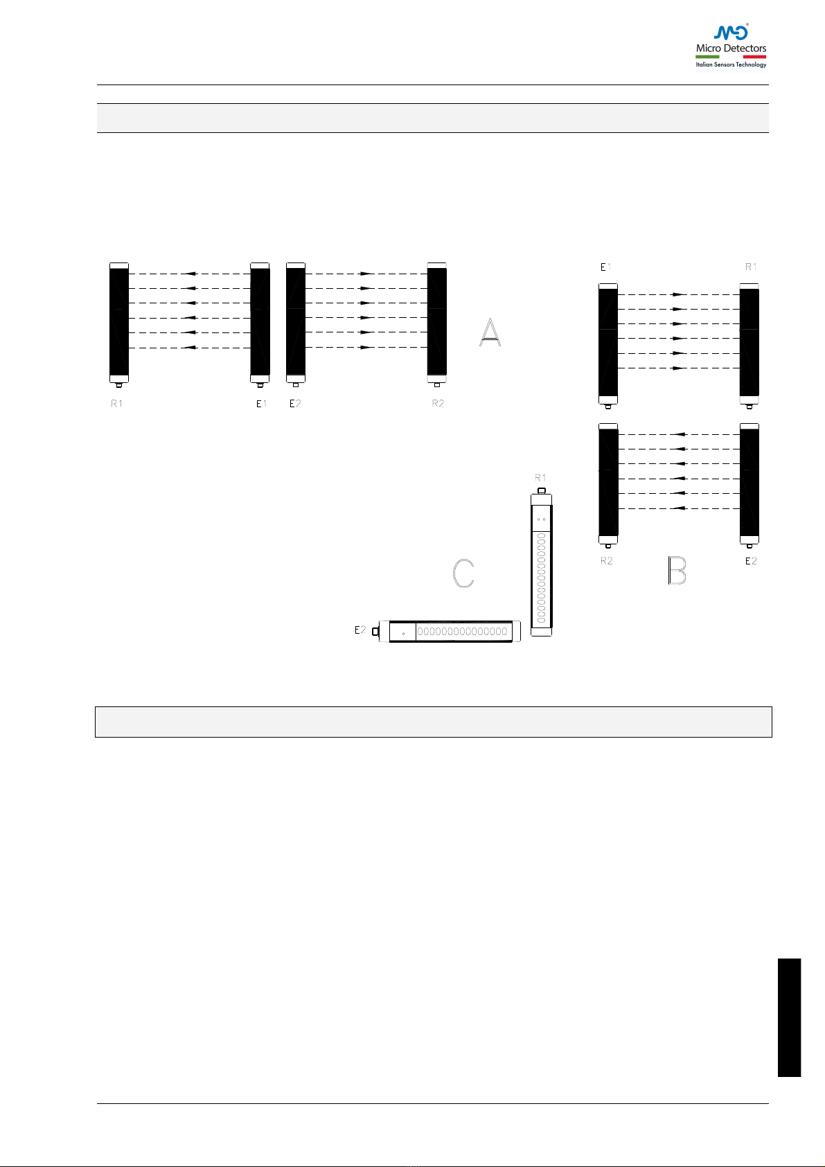
Vertical positioning of the light curtain
Models with 14, 20mm resolution
!These models are suitable for fingers detection.
Models with 30, 40mm resolution
!These models are suitable for hand detection.
The minimum safety distance Sis calculated
according to the following formula:
S = 2000 (t1+ t2) + 8(D-14)
(D=resolution)
This formula is valid for distances Sbetween 100
and 500 mm. If, according to the calculation, S
exceeds 500 mm, the distance can be reduced
down to a minimum of 500 mm using the following
formula:
S = 1600 (t1+ t2) + 8(D-14)
If, in view of the particular configuration of the
machine, the dangerous zone can be reached from
above, the highest beam of the light curtain must
be at a height H(from resting surface G) whose
value is determined by using the ISO 13855
Standard.
G
Figure 12 -
Vertical positioning
14mm, 20mm, 30mm, 40mm
Models with 50, 90mm resolution
!These models are suitable for detecting the arm
or the leg and must not be used to detect
fingers or hands.
The minimum safety distance Sis determined
according to the following formula:
S = 1600 (t1+ t2) + 850
èIn every case the height Hof the highest beam
from resting surface Gmust not be smaller
than 900 mm, while the height of the lowest
beam Pmust not be bigger than 300 mm (ISO
13855 Standard).
G
Figure 13 - 50mm, 90mm
Light curtain
point of
danger
direction
of
approach
reference plane
Light curtain
point of
danger
direction
of
approach
reference plane
LS4 SAFETY LIGHT CURTAIN
14 CAT8ELS1251403 • 26/06/2018
English
Multibeam Models
!These models are suitable for whole
body detection and must not be used to
detect arms or legs.
The minimum safety distance Sis determined
according to the following formula:
S = 1600 (t1+ t2) + 850
The recommend height H from the reference
surface G(ground) is as follows (ISO 13855
Standard) :
G
Figure 14 - Multibeam
MODEL
BEAMS
Recommended height H (mm)
LS4 2B
LS4 3B
LS4 4B
2
3
4
400 – 900
300 – 700 – 1100
300 – 600 – 900 - 1200
Table 3 - Height H of Multibeam models
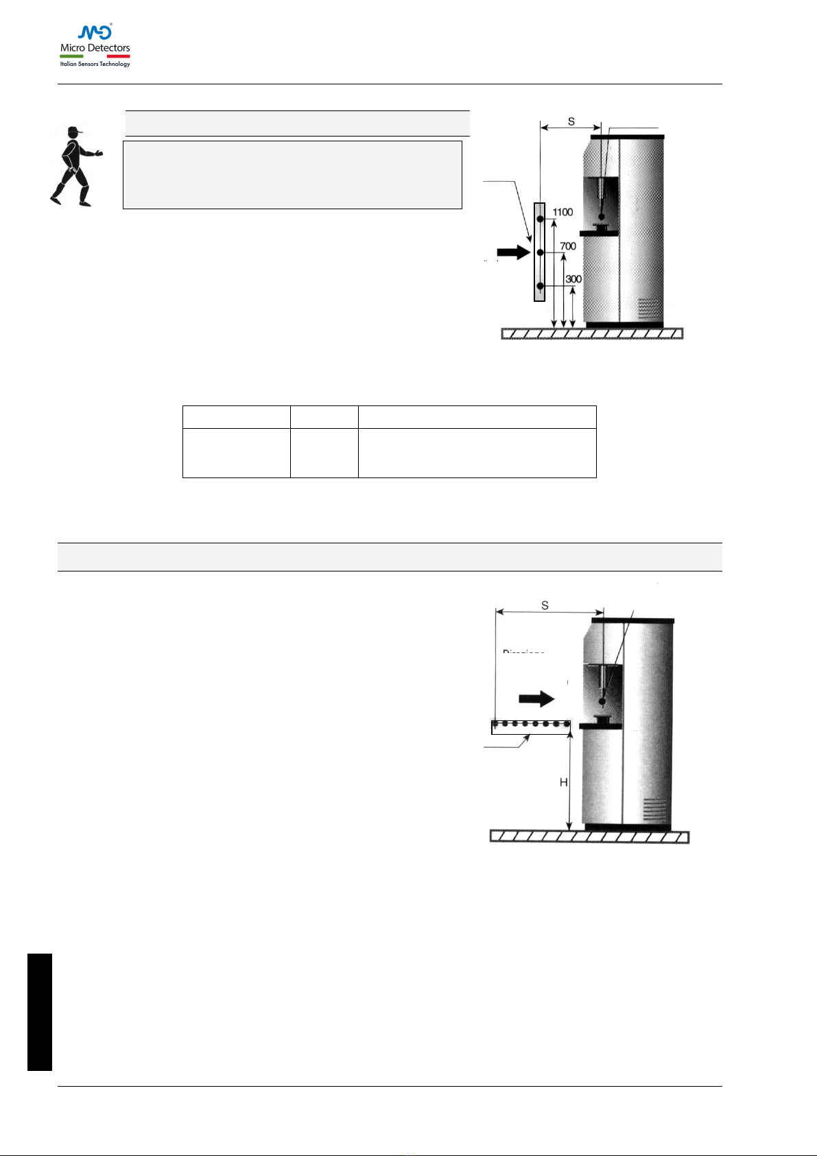
Horizontal positioning of the light curtain
When the direction of approach of the body is parallel
to the plane of the protected area, the light curtain
must be positioned so that the distance between the
far end of the dangerous area and the outermost
beam is equal to or greater than the minimum safety
distance Scalculated as follows:
S = 1600(t1+ t2) + 1200 – 0.4H
where His the height of the protected surface from
the machine reference plane;
H = 15(D-50)
(D=resolution)
In this case, Hmust always be less than of 1m
(ISO 13855 Standard).
G
Figure 15 - Horizontal positioning
Light grid
point of
danger
direction
of
approach
reference plane
Light curtain
point of
danger
direction
of approach
reference plane

LS4 SAFETY LIGHT CURTAIN
CAT8ELS1251403 • 26/06/2018 15
English
Electrical connections
WARNINGS
Before making electrical connections, make sure that the mains voltage matches the one indicated
in the technical data.
!The Emitter and Receiver must be powered at a 24Vdc±20% (PELV, in compliance with
the standard EN 60204-1 (Chapter 6.4)).
The electrical connections must be made according to the wiring diagrams provided in this
manual.
In particular, do not connect other devices to the connectors of the Emitter and Receiver.
To guarantee reliable operation using a diode bridge power supply unit, its output capacity must
be at least 2000µF for each A absorbed.
Layout of the connectors on MASTER/SLAVE light curtain
Figure 16 - Connector layout
SLAVE primary connector
SLAVE2 secondary connector
SLAVE
SLAVE 2
SLAVE2 primary connector
MASTER secondary connector
MASTER
MASTER primary
connector

LS4 SAFETY LIGHT CURTAIN
16 CAT8ELS1251403 • 26/06/2018
English
Emitter connections
LS4E/**-***B - LS4E/**-*** (with integrated control functions) - LS4E/**-***M (MASTER models)
M12 5-pin primary connectors.
PIN
COLOUR
NAME
TYPE
DESCRIPTION
1
Brown
24VDC
INPUT
24VDC power supply
2
White
RANGE0
Light curtain configuration
complying with the EN61131-2 standard
(ref. Table 5)
3
Blue
0VDC
0VDC power supply
4
Black
RANGE1
Light curtain configuration
complying with the EN61131-2 standard
(ref. Table 5)
5
Grey
FE
Ground connection
Table 4 - M12, 5 pin
Master/Standard/with integrated control functions TX
RANGE AND TEST SELECTION - (PRIMARY CONNECTOR M12, 5 PIN)
PIN 4
PIN 2
MEANING
24V
0V
Selection HIGH Range
0V
24V
Selection LOW Range
0V
0V
Emitter in TEST
24V
24V
Selection error
Table 5 – Range and TEST selection
èFor correct operation of the light curtain, pins 2 and 4 of the Emitter must be
connected as indicated in Table 5.
LS4E/**-***F - LS4E/**-***S (SLAVE/SLAVE2 models) - M12, 5-pin primary connector.
PIN
COLOUR
NAME
DESCRIPTION
1
Brown
24VDC
24VDC power supply
2
White
LINE_A
Communication
MASTER-SLAVE
3
Blue
0VDC
0VDC power supply
4
Black
LINE_B
Communication
MASTER-SLAVE
5
Grey
FE
Ground connection
Table 6 - M12, 5-pin Primary Slave TX
LS4E/**-***M (MASTER models) – M12, 5-pin secondary connector.
LS4E/**-***S (SLAVE2 models) – M12, 5-pin secondary connector.
PIN
COLOUR
NAME
DESCRIPTION
1
Brown
24VDC
24VDC power supply
2
White
LINE_A
Communication
MASTER-SLAVE
3
Blue
0VDC
0VDC power supply
4
Black
LINE_B
Communication
MASTER-SLAVE
5
Grey
FE
Ground connection
Table 7 - M12, 5-pin Secondary TX
LS4 SAFETY LIGHT CURTAIN
CAT8ELS1251403 • 26/06/2018 17
English
Receiver connections
LS4R/**-***B models - M12, 5-pin connector.
PIN
COLOUR
NAME
TYPE
DESCRIPTION
OPERATION
1
Brown
24VDC
-
24VDC power supply
-
2
White
OSSD1
OUT
Static safety output 1
PNP active high
3
Blue
0VDC
-
0VDC power supply
-
4
Black
OSSD2
OUT
Static safety output 2
PNP active high
5
Grey
FE
-
Ground connection
-
Table 8 - M12, 5 pins Primary RX
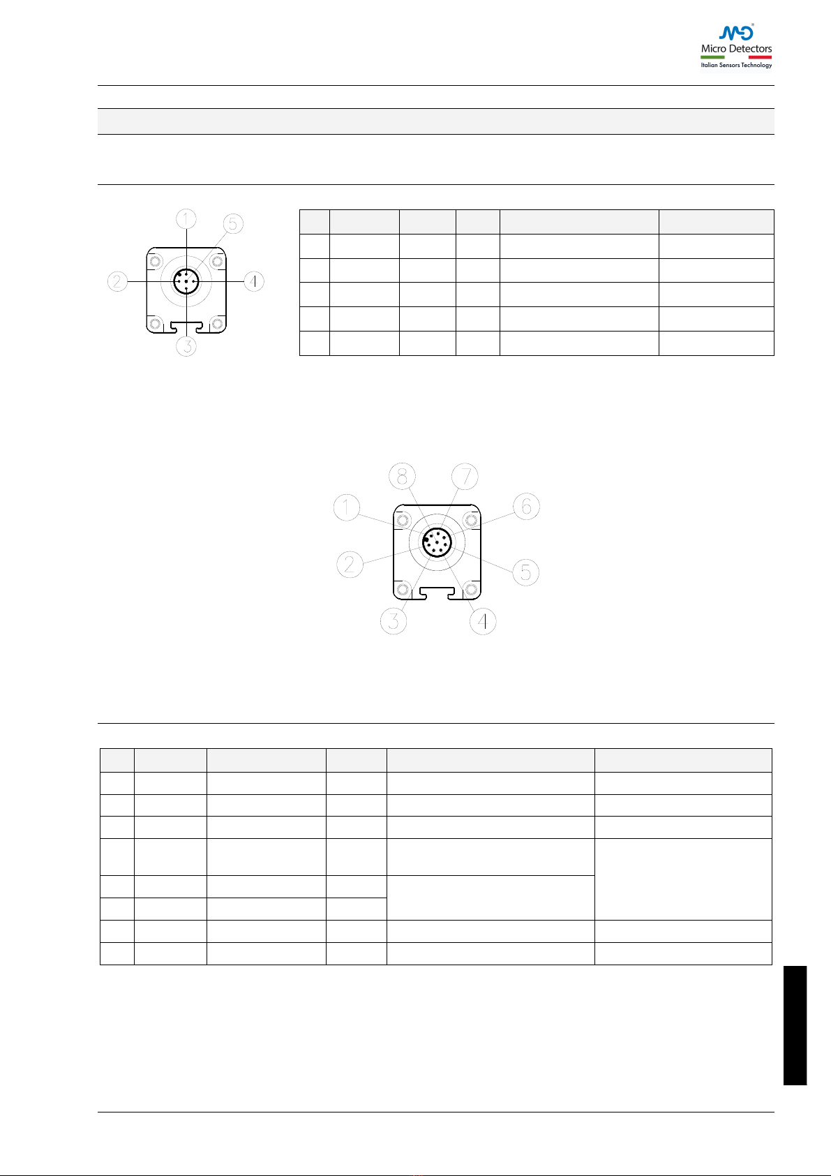
LS4R/**-*** (models with integrated control functions) - M12, 8-pin connector.
LS4R/**-***M (MASTER models) - M12, 8-pin primary connector.
PIN
COLOUR
NAME
TYPE
DESCRIPTION
OPERATION
1
White
OSSD1
OUTPUT
Static safety output 1
PNP active high
2
Brown
24VDC
-
24VDC power supply
-
3
Green
OSSD2
OUTPUT
Static safety output 2
PNP active high
4
Yellow
K1_K2/RESTART
INPUT
Feedback from external
contactors
Complying with the
EN61131-2 standard
(ref. Par. "Configuration
and operating modes"
page 19)
5
Grey
SEL_A
INPUT
Light curtain configuration
6
Pink
SEL_B
INPUT
7
Blue
0VDC
-
0VDC power supply
-
8
Red
FE
-
Ground connection
-
Table 9 - M12, 8 pins RX
LS4 SAFETY LIGHT CURTAIN
18 CAT8ELS1251403 • 26/06/2018
English
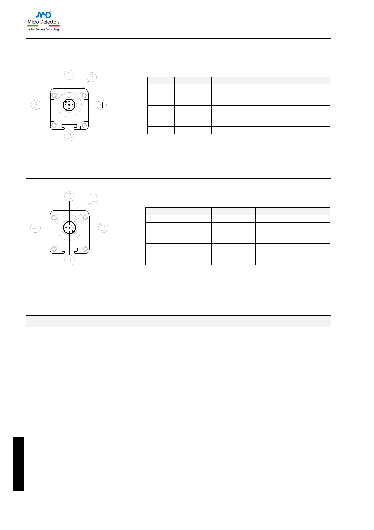
LS4R/**-***F - LS4R/**-***S (SLAVE/SLAVE2 models) - M12, 5-pin primary connectors.
PIN
COLOUR
NAME
DESCRIPTION
1
Brown
24VDC
24VDC power supply
2
White
LINE_A
Communication
MASTER-SLAVE
3
Blue
0VDC
0VDC power supply
4
Black
LINE_B
Communication
MASTER-SLAVE
5
Grey
FE
Ground connection
Table 10 - M12, 5 pins Primary Slave RX
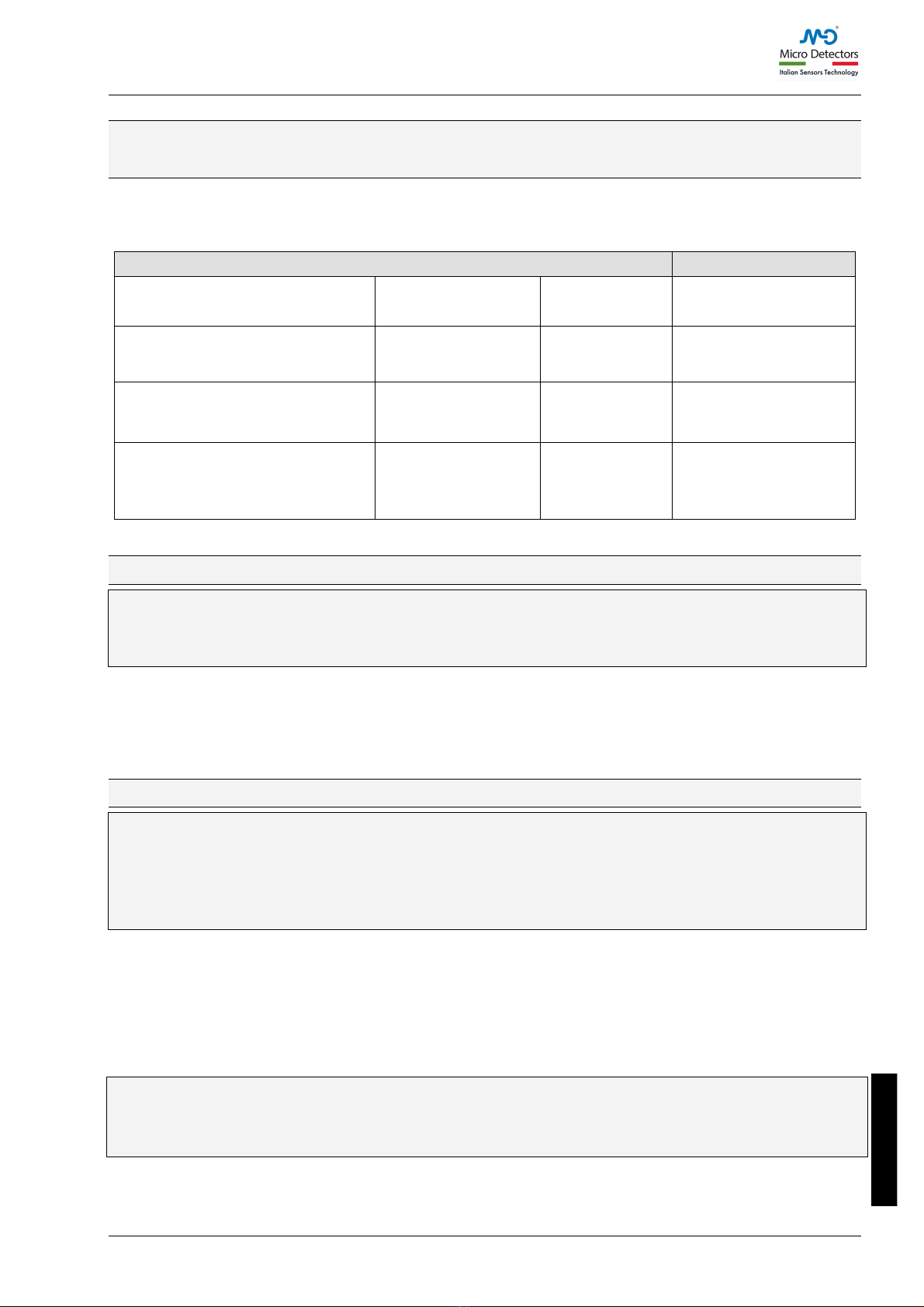
LS4R/**-***M (MASTER models) - M12, 5-pin Secondary Connector.
LS4R/**-***S (SLAVE2 models) - M12, 5-pin Secondary Connector.
PIN
COLOUR
NAME
DESCRIPTION
1
Brown
24VDC
24VDC power supply
2
White
LINE_A
Communication
MASTER-SLAVE
3
Blue
0VDC
0VDC power supply
4
Black
LINE_B
Communication
MASTER-SLAVE
5
Grey
FE
Ground connection
Table 11 - M12, 5 pin Secondary RX
Warnings regarding connection cables
•For connections with a length of more than 50m, use cables having a cross-section
of at least 1mm2.
•It is good practice to keep the power supply of the light curtain separate from that
of other electric power equipment (electric motors, inverters, frequency variators)
or other sources of disturbance.
•Connect the Emitter and Receiver to the ground outlet.
•The connection cables must follow a different route from that of other power
cables.
LS4 SAFETY LIGHT CURTAIN
CAT8ELS1251403 • 26/06/2018 19
English
Configuration and operating modes
(Master Models / With integrated control functions)
The operating mode of the LS4 light curtain is set by making suitable connections on the M12 – 8-
pin connector of the Receiver (Table 12).
CONNECTIONS
OPERATING MODE
K1_K2/restart (PIN 4)
connected to : 24VDC
SEL_A (PIN 5)
connected to :
24VDC
SEL_B (PIN 6)
connected to :
0VDC
AUTOMATIC
(Figure 17)
K1_K2/restart (PIN 4)
connected to : 24VDC
(via set of NC contacts of K1K2)
SEL_A (PIN 5)
connected to :
24VDC
SEL_B (PIN 6)
connected to :
0VDC
AUTOMATIC
with control K1K2
(Figure 18)
K1_K2/restart (PIN 4)
connected to : 24VDC (via RESTART
button)
SEL_A (PIN 5)
connected to :
0VDC
SEL_B (PIN 6)
connected to :
24VDC
MANUAL
(Figure 19)
K1_K2/restart (PIN 4)
connected to : 24VDC
(via RESTART button and set of NC
contacts of K1K2)
SEL_A (PIN 5)
connected to :
0VDC
SEL_B (PIN 6)
connected to :
24VDC
MANUAL
with control K1K2
(Figure 20)
Table 12 –Setting of manual/automatic mode
Automatic operation
!If the LS4 light curtain is used in AUTOMATIC mode, it will not be equipped with a
start/restart interlock circuit. In most applications, this safety function is compulsory.
Carefully assess the risks analysis of your own application.
In this operating mode, the OSSD1 and OSSD2 safety outputs follow the status of the light curtain :
•with guarded area free, the outputs are ON.
•with guarded area occupied, they are OFF.
Manual operation
!Use in manual mode (start/restart interlock ON) is compulsory if the safety device
controls an opening in order to protect a dangerous area and if a person, after
passing through the opening, can remain in the dangerous area without being
detected (use as 'trip device' according to IEC 61496). Failure to comply with this
regulation may result in very serious hazards for the persons exposed.
In this operating mode, the safety outputs OSSD1 and OSSD2 are activated in a condition of free
protected area and after having received the RESTART signal via push-button or a specific
command on the K1K2/RESTART input).
Following occupation of the protected area, the outputs will be disabled. For re-activation, repeat
the sequence described above.
The RESTART command is active with transition 0Vdc -> 24Vdc -> 0Vdc.
The duration of the command must be within 100ms and 5s.
!The Restart command must be installed outside the danger area in a position where
the danger area and the entire work area concerned are clearly visible.
!It must not be possible to reach the control from inside the danger area.

LS4 SAFETY LIGHT CURTAIN
20 CAT8ELS1251403 • 26/06/2018
English
Connection of external contactors K1 and K2
In both operating modes, it is possible to activate control of the external contactors K1/K2 (series
of contacts). If this control is to be used, it is necessary to connect pin 4 of the M12 8-pin
connector of the Receiver with the power supply (24VDC) via a set of NC contacts (feedback) of
the external contactors.
!In the case of manual operation, the RESTART button in series with the NC contacts
(feedback) of the external contactors K1/K2 (Figure 20) must also be present.
!If the application requires it, the response time of the external contactors must be
verified by an additional device.
Figure 17 - Automatic
Figure 18 – Automatic with K1K2 feedback
Figure 19 - Manual
Figure 20 – Manual with K1K2 feedback
Other manuals for LS4 Series
1
Table of contents
Popular Lighting Equipment manuals by other brands

Coitech
Coitech LS1768B-30 quick start guide

Linergy
Linergy VA03N20EBRD Installation

Signtex Lighting
Signtex Lighting Moonlite LED MOE-RE Series Installation instructions and owner's manual

NVC
NVC KANSAS PRO instructions

Lopolight
Lopolight 300-038 installation guide

Rollei
Rollei LUMIS Magnetic Smartphone Light Bi-Color user manual


