micro-trak 17632 User manual

RAVEN 440/450 CONNECTION
P/N 17601
(15 FEET)
GROUND
POWER
SEE TABLE
FOR OPTIONAL
EXTENSION CABLES
P/N 17359
P/N 17358
(20 FEET)
SECTION BYPASS VALVE
RPM
CONTROL VALV
E
RUN/HOLD w/DUST COVER
BROWN TIES
GRAY TIE
BROWN TIE
20’
5’
20’
Instructions for Micro-Trak
Seed Rate Control Systems
Used with Raven Controllers
440/450 - Single Section
P/N 50289 Rev A • © 2009 • Page 1
1. Install system components and harnessing per general
instruction manual (Micro-Trak P/N 17632).
2. See attached system and wiring diagrams for Raven
440/450-specic harnessing. Note the dierent diagrams for
single drive or multi-drive systems.
3. See page 10 for Calculating Flow Cal or Pulses per 1000 Seeds
to be entered in the 440/450 Application Rate Controller Pro-
gram.
Single Drive Harness Kit System Diagram
OPTIONAL 10-PIN CABLES
P/N 13220 5' CABLE
P/N 13221 10' CABLE
P/N 13222 15' CABLE
P/N 13223 20' CABLE
P/N 13224 25' CABLE
P/N 14142 50' CABLE
OPTIONAL 5-PIN CABLES
P/N 14482 5' CABLE
P/N 14483 10' CABLE
P/N 14484 15' CABLE
P/N 14485 20' CABLE
P/N 14486 25' CABLE

P/N 50289 Rev A • © 2009 • Page 2
16-PIN AMP
(11948)
1
2
3
4
5
6
7
8
9
10
11
12
13
14
15
16
14 GA. BLK
16 GA. BRN
20 GA. GRN
20 GA. VIO
16 GA. RED
16 GA. ORG
16 GA. WHT
20 GA. GRY
20 GA. YEL
20 GA. BLU
14 GA. RED
GND
BM 2
SERVO +
SERVO -
BM 3
BM 1
R/H SIG (0=HOLD)
FLOW GND
+5 V
FLOW SIG
16 GA. ORG
16 GA. BRN
16 GA. RED
16 GA. BLK
20 GA. BLU
20 GA. YEL
20 GA. GRY
20 GA. GRN
29 GA. VIO
16 GA. WHT
15 FT.
P/N 17601
HEAT SHRINK
12 GA. BLK
12 GA. GRN
20 FT.
BAND SPLICE &
HEAT SHRINK (3 PLCS)
GND
+12 VDC (VBAT)
30A
A
B
C
D
E
A
B
C
D
E
20 GA. GRN
20 GA. BRN
20 GA. WHT
20 GA. RED
20 GA. BLK
5-PIN
M/P
TOWER
5-PIN
M/P
SHROUD
A
B
C
D
E
F
G
H
J
K
A
B
C
D
E
F
G
H
J
K
20 GA. BRN
20 GA. RED
20 GA. ORG
20 GA. YEL
20 GA. GRN
20 GA. BLU
20 GA. VIO
20 GA. GRY
20 GA. WHT
20 GA. BLK
10-PIN
M/P
TOWER
10-PIN
M/P
SHROUD
SEE TABLE FOR
OPTIONAL EXTENSION
CABLE LENGTHS
20 GA. GRN
20 GA. BRN
20 GA. WHT
20 GA. RED
20 GA. BLK
A
B
C
D
E
5-PIN
M/P
TOWER
20 GA. BRN
20 GA. RED
20 GA. ORG
20 GA. YEL
20 GA. GRN
20 GA. BLU
20 GA. VIO
20 GA. GRY
20 GA. WHT
20 GA. BLK
A
B
C
D
E
F
G
H
J
K
10-PIN
M/P
SHROUD
18 GA. RED
18 GA. BLK
P/N 17358
5-PIN
M/P
SHROUD
A
B
C
D
E
A
B
C
D
E
F
G
H
J
K
10-PIN
M/P
TOWER
18 GA. RED
18 GA. WHT
18 GA. BLK
18 GA. RED
18 GA. BLK
18 GA. BLK
18 GA. WHT
18 GA. RED
BROWN TIE
18 GA. RED
18 GA. BLK
A
B
2-PIN M/P
TOWER
SECTION BYPASS VALVE (+12VDC)
SECTION BYPASS VALVE (GROUND)
BROWN TIE (2X)
20 FT.
GRAY TIE
20 FT.
P/N 17359
HEAT SHRINK
18 GA. RED
18 GA. WHT
18 GA. BLK
A
B
C
A
B
C
A
B
C
3-PIN
M/P
TOWER
3-PIN
M/P
TOWER
3-PIN
W/P
SHROUD
3-PIN
M/P
SHROUD
A
B
C
DUST COVER
(P/N 13107)
RUN/HOLD SIGNAL
RUN/HOLD POWER
RUNHOLD GROUND
RPM SIGNAL
RPM POWER
RPM GROUND
CONTROL VALVE -
CONTROL VALVE +
240 IN.
5 FT.
18 GA. RED
18 GA. BLK
18 GA. RED
18 GA. WHT
18 GA. BLK
Single Drive Harness Kit Wiring Diagram
OPTIONAL 10-PIN CABLES
P/N 13220 5' CABLE
P/N 13221 10' CABLE
P/N 13222 15' CABLE
P/N 13223 20' CABLE
P/N 13224 25' CABLE
P/N 14142 50' CABLE
OPTIONAL 5-PIN CABLES
P/N 14482 5' CABLE
P/N 14483 10' CABLE
P/N 14484 15' CABLE
P/N 14485 20' CABLE
P/N 14486 25' CABLE
Instructions for Micro-Trak
Seed Rate Control Systems
Raven Controllers
440/450 - Single Section

SEE TABLES FOR
OPTIONAL EXTENSION
CABLES
LEFT SECTION
BYPASS VALVE
LEFT RPM
RUN/HOLD wDUST COVER
CENTER RPM
P/N 17307
P/N 17308
P/N 17830
w/DUST COVER
ORANGE TIE
(240”)
CENTER SECTION
BYPASS VALVE
RIGHT SECTION
BYPASS VALVE
RIGHT RPM wDUST COVER
CONTROL VALVE
RAVEN 440/450 TO MICRO-TRAK
SEED RATE CONTROL SYSTEM
THREE SECTION DIAGRAM
RED TIE
(120”)
BROWN TIE
(240”)
BROWN TIES
(240”)
RED TIES
(120”)
ORANGE TIES
(240”)
GRAY TIE
(60”)
240”
CONNECT TO
RAVEN 440/450
P/N 17582
w/o POWER
(120 IN.)
POWER
GROUND
P/N 50289 Rev A • © 2009 • Page 3
OPTIONAL 10-PIN CABLES
P/N 13220 5' CABLE
P/N 13221 10' CABLE
P/N 13222 15' CABLE
P/N 13223 20' CABLE
P/N 13224 25' CABLE
P/N 14142 50' CABLE
Three Drive Harness Kit System Diagram
Instructions for Micro-Trak
Seed Rate Control Systems
Used with Raven Controllers
440/450 - Three Section
OPTIONAL 7-PIN CABLES
P/N 14146 5' CABLE
P/N 14147 10' CABLE
P/N 14103 15' CABLE
P/N 14236 20' CABLE
P/N 14237 25' CABLE

P/N 50289 Rev A • © 2009 • Page 4
Three Drive Harness Kit Wiring Diagram
OPTIONAL 10-PIN CABLES
P/N 13220 5' CABLE
P/N 13221 10' CABLE
P/N 13222 15' CABLE
P/N 13223 20' CABLE
P/N 13224 25' CABLE
P/N 14142 50' CABLE
Instructions for Micro-Trak
Seed Rate Control Systems
Used with Raven Controllers
440/450 - Three Section
OPTIONAL 7-PIN CABLES
P/N 14146 5' CABLE
P/N 14147 10' CABLE
P/N 14103 15' CABLE
P/N 14236 20' CABLE
P/N 14237 25' CABLE
A
B
C
D
E
F
G
18 GA. YEL
18 GA. BRN
18 GA. GRY
18 GA. BLK
10 GA. ORG
18 GA. RED
10 GA. BLU
18 GA. YEL
18 GA. BRN
18 GA. GRY
18 GA. BLK
10 GA. ORG
18 GA. RED
10 GA. BLU
A
B
C
D
E
F
G
PN 17830
A
B
C
D
E
F
G
7-PIN
M/P
SHROUD
7-PIN
M/P
TOWER
7-PIN
M/P
SHROUD
A
B
C
D
E
5-PIN
M/P
TOWER
SEE TABLES FOR
OPTIONAL EXTENSION
CABLE LENGTHS
A
B
C
D
E
F
G
H
J
K
10-PIN
M/P
TOWER
20 GA. BRN
20 GA. RED
20 GA. ORG
20 GA. YEL
20 GA. GRN
20 GA. BLU
20 GA. VIO
20 GA. GRY
20 GA. WHT
20 GA. BLK
A
B
C
D
E
F
G
H
J
K
10-PIN
M/P
TOWER
10-PIN
M/P
SHROUD
A
B
C
D
E
F
G
H
J
K
A
B
C
D
E
F
G
H
J
K
10-PIN
M/P
SHROUD
A
B
C
D
E
F
G
H
J
K
20 GA. BRN
20 GA. RED
20 GA. ORG
20 GA. YEL
20 GA. GRN
20 GA. BLU
20 GA. VIO
20 GA. GRY
20 GA. WHT
20 GA. BLK
10-PIN
M/P
TOWER
w/DUST
COVER
HEAT SHRINK
5-PIN
M/P
SHROUD
A
B
C
D
E
20 GA. RED
20 GA. RED
20 GA. RED
20 GA. BLK
20 GA. BLK
PN 17307
120 IN.
240 IN.
240 IN.
RED TIE
BROWN TIE
PN 17308
240 IN.
120 IN.
18 GA. RED
18 GA. BLK
18 GA. RED
18 GA. BLK
18 GA. RED
18 GA. BLK
A
B
A
B
A
B
2-PIN M/P
TOWER
2-PIN M/P
TOWER
2-PIN M/P
TOWER
+12V
GND
+12V
GND
+12V
GND
DUST
COVER
SECTION 1 BYPASS VALVE
SECTION 2 BYPASS VALVE
SECTION 3 BYPASS VALVE
ORANGE TIE
10-PIN
M/P
TOWER
A
B
C
D
E
F
G
H
J
K
18 GA. RED
18 GA. WHT
18 GA. BLK
18 GA. RED
18 GA. BLK
18 GA. BLK
18 GA. WHT
18 GA. RED
18 GA. RED
18 GA. REG
240 IN.
240 IN.
60 IN.
BROWN TIE (2X)
ORANGE TIE (2X)
GRAY TIE
RED TIE (2X)
18 GA. RED
18 GA. WHT
18 GA. BLK
18 GA. RED
18 GA. WHT
18 GA. BLK
18 GA. RED
18 GA. WHT
18 GA. BLK
A
B
C
A
B
C
A
B
C
A
B
C
3-PIN
M/P
TOWER
3-PIN
M/P
TOWER
3-PIN
M/P
TOWER
3-PIN
M/P
SHROUD
3-PIN
M/P
TOWER
DUST
COVER
DUST
COVER
SIGNAL
POWER SECTION 1 RPM
GROUND
SIGNAL
POWER SECTION 3 RPM
GROUND
SIGNAL
POWER SECTION 2 RPM
GROUND
CONTROL VALVE -
CONTROL VALVE +
RUN/HOLD SIGNAL
RUN/HOLD POWER
RUN/HOLD GROUND
A
B
C
A
B
C
A
B
C
18 GA. RED
18 GA. WHT
18 GA. BLK
18 GA. RED
18 GA. BLK
HEAT SHRINK
16-PIN AMP
FEMALE CPC
(206037-1)
GND
BM2
SERVO
SERVO
BM3
BM1
BM4
BM5
BM6
REM/HOLD
FLOW GND
+5V FLOW PWR
FLOW SIG
(CONS) 12V SW
BM7
+12VDC
1
2
3
4
5
6
7
8
9
10
11
12
13
14
15
16
14 GA. BLU
18 GA. BRN
20 GA. YEL
20 GA. GRN
18 GA. GRY
18 GA. YEL
18 GA. BLK
18 GA. RED
16 GA. ORG
16 GA. BRN
20 GA. BLU
20 GA. VIO
20 GA. GRY
16 GA. RED
16 GA. WHT
14 GA. ORG
30A
BAND SPLICE &
HEAT SHRINK (4)
20 FT.
10 GA. WHT
GND
+12VDC (VBAT)
10 GA. BLK SPLIT LOOM
18 GA. YEL
18 GA. BRN
18 GA. GRY
18 GA. BLK
10 GA. ORG
18 GA. RED
10 GA. BLU
A
B
C
D
E
F
G
WAYTEK OUTLET 120 IN.
P/N 17582
20 GA. GRY
20 GA. VIO
20 GA. BLU
20 GA. YEL
20 GA. GRN
16 GA. ORG
16 GA. BLK
16 GA. BRN
16 GA. RED
16 GA. WHT
A
B
C
D
E
F
G
H
J
K
7-PIN MIXED TOWER
10-PIN M/P SHROUD

PN 17307
SEE TABLE FOR
OPTIONAL EXTENSION
CABLE
PN 17308
SECTION 4
BYPASS VALVE
SECTION 4 RPM
SECTION 5
BYPASS VALVE
SECTION 5 RPM
SECTION 1
BYPASS VALVE
SECTION 1 RPM
SECTION 2
BYPASS VALVE
SECTION 2
BYPASS VALVE
SECTION 3 RPM
SECTION 2 RPM
RUN/HOLD w/DUST COVER
CONTROL VALVE
PN 17837
P/N 17830
ORANGE TIE
(240”)
RAVEN 440/450 TO MICRO-TRAK
SEED RATE CONTROL SYSTEM
FIVE SECTION DIAGRAM
RED TIE
(120”)
BROWN TIE
(240”)
BROWN TIES
(240”)
RED TIES
(120”)
ORANGE TIES
(240”)
GRAY TIE
(60”)
240”
YELLOW TIES
(240”)
YELLOW TIE
(240”)
GREEN TIES
(120”)
GREEN TIE
(120”)
RAVEN 440/450 CONNECTION
P/N 17582
w/o POWER
(120 IN.)
POWER
GROUND
Five Drive Harness Kit System Diagram
Instructions for Micro-Trak
Seed Rate Control Systems
Used with Raven Controllers
440/450 - Five Section
P/N 50289 Rev A • © 2009 • Page 5
OPTIONAL 10-PIN CABLES
P/N 13220 5' CABLE
P/N 13221 10' CABLE
P/N 13222 15' CABLE
P/N 13223 20' CABLE
P/N 13224 25' CABLE
P/N 14142 50' CABLE
OPTIONAL 7-PIN CABLES
P/N 14146 5' CABLE
P/N 14147 10' CABLE
P/N 14103 15' CABLE
P/N 14236 20' CABLE
P/N 14237 25' CABLE

A
B
C
D
E
F
G
18 GA. YEL
18 GA. BRN
18 GA. GRY
18 GA. BLK
10 GA. ORG
18 GA. RED
10 GA. BLU
18 GA. YEL
18 GA. BRN
18 GA. GRY
18 GA. BLK
10 GA. ORG
18 GA. RED
10 GA. BLU
A
B
C
D
E
F
G
PN 17830
A
B
C
D
E
F
G
7-PIN
M/P
SHROUD
7-PIN
M/P
TOWER
7-PIN
M/P
SHROUD
A
B
C
D
E
5-PIN
M/P
TOWER
SEE TABLES FOR
OPTIONAL EXTENSION
CABLE LENGTHS
A
B
C
D
E
F
G
H
J
K
10-PIN
M/P
TOWER
20 GA. BRN
20 GA. RED
20 GA. ORG
20 GA. YEL
20 GA. GRN
20 GA. BLU
20 GA. VIO
20 GA. GRY
20 GA. WHT
20 GA. BLK
A
B
C
D
E
F
G
H
J
K
10-PIN
M/P
TOWER
10-PIN
M/P
SHROUD
A
B
C
D
E
F
G
H
J
K
A
B
C
D
E
F
G
H
J
K
10-PIN
M/P
SHROUD
A
B
C
D
E
F
G
H
J
K
20 GA. BRN
20 GA. RED
20 GA. ORG
20 GA. YEL
20 GA. GRN
20 GA. BLU
20 GA. VIO
20 GA. GRY
20 GA. WHT
20 GA. BLK
10-PIN
M/P
TOWER
HEAT SHRINK
5-PIN
M/P
SHROUD
A
B
C
D
E
20 GA. RED
20 GA. RED
20 GA. RED
20 GA. BLK
20 GA. BLK
PN 17307
120 IN.
240 IN.
240 IN.
RED TIE
BROWN TIE
PN 17308
240 IN.
120 IN.
18 GA. RED
18 GA. BLK
18 GA. RED
18 GA. BLK
18 GA. RED
18 GA. BLK
A
B
A
B
A
B
2-PIN M/P
TOWER
2-PIN M/P
TOWER
2-PIN M/P
TOWER
+12V
GND
+12V
GND
+12V
GND
DUST
COVER
SECTION 1 BYPASS VALVE
SECTION 2 BYPASS VALVE
SECTION 3 BYPASS VALVE
ORANGE TIE
10-PIN
M/P
TOWER
A
B
C
D
E
F
G
H
J
K
18 GA. RED
18 GA. WHT
18 GA. BLK
18 GA. RED
18 GA. BLK
18 GA. BLK
18 GA. WHT
18 GA. RED
18 GA. RED
18 GA. REG
240 IN.
240 IN.
60 IN.
BROWN TIE (2X)
ORANGE TIE (2X)
GRAY TIE
RED TIE (2X)
18 GA. RED
18 GA. WHT
18 GA. BLK
18 GA. RED
18 GA. WHT
18 GA. BLK
18 GA. RED
18 GA. WHT
18 GA. BLK
A
B
C
A
B
C
A
B
C
A
B
C
3-PIN
M/P
TOWER
3-PIN
M/P
TOWER
3-PIN
M/P
TOWER
3-PIN
M/P
SHROUD
3-PIN
M/P
TOWER
DUST
COVER
DUST
COVER
SIGNAL
POWER SECTION 1 RPM
GROUND
SIGNAL
POWER SECTION 3 RPM
GROUND
SIGNAL
POWER SECTION 2 RPM
GROUND
CONTROL VALVE -
CONTROL VALVE +
RUN/HOLD SIGNAL
RUN/HOLD POWER
RUN/HOLD GROUND
SECTION 4 BYPASS VALVE
SECTION 5 BYPASS VALVE
SIGNAL
POWER SECTION 5 RPM
GROUND
SIGNAL
POWER SECTION 4 RPM
GROUND
2-PIN M/P
TOWER
A
B
C
A
B
C
A
B
C
18 GA. RED
18 GA. WHT
18 GA. BLK
18 GA. RED
18 GA. BLK
18 GA. RED
18 GA. BLK
A
B
A
B
C
A
B
2-PIN M/P
TOWER
3-PIN
M/P
TOWER
+12V
GND
+12V
GND
18 GA. RED
18 GA. WHT
18 GA. BLK
18 GA. RED
18 GA. BLK
18 GA. RED
18 GA. WHT
18 GA. BLK
A
B
C
3-PIN
M/P
TOWER
240 IN.
240 IN.
120 IN.
GREEN TIE
YELLOW TIE (2X)
YELLOW TIE
GREEN TIE (2X)
120 IN.
HEAT SHRINK
A
B
C
D
E
F
G
H
J
K
10-PIN
M/P
SHROUD
18 GA. RED
18 GA. BLK
18 GA. RED
18 GA. BLK
18 GA. RED
18 GA. WHT
18 GA. BLK
18 GA. RED
18 GA. WHT
18 GA. BLK
16-PIN AMP
FEMALE CPC
(206037-1)
GND
BM2
SERVO
SERVO
BM3
BM1
BM4
BM5
BM6
REM/HOLD
FLOW GND
+5V FLOW PWR
FLOW SIG
(CONS) 12V SW
BM7
+12VDC
1
2
3
4
5
6
7
8
9
10
11
12
13
14
15
16
14 GA. BLU
18 GA. BRN
20 GA. YEL
20 GA. GRN
18 GA. GRY
18 GA. YEL
18 GA. BLK
18 GA. RED
16 GA. ORG
16 GA. BRN
20 GA. BLU
20 GA. VIO
20 GA. GRY
16 GA. RED
16 GA. WHT
14 GA. ORG
30A
BAND SPLICE &
HEAT SHRINK (4)
20 FT.
10 GA. WHT
GND
+12VDC (VBAT)
10 GA. BLK SPLIT LOOM
18 GA. YEL
18 GA. BRN
18 GA. GRY
18 GA. BLK
10 GA. ORG
18 GA. RED
10 GA. BLU
A
B
C
D
E
F
G
WAYTEK OUTLET 120 IN.
P/N 17582
20 GA. GRY
20 GA. VIO
20 GA. BLU
20 GA. YEL
20 GA. GRN
16 GA. ORG
16 GA. BLK
16 GA. BRN
16 GA. RED
16 GA. WHT
A
B
C
D
E
F
G
H
J
K
7-PIN MIXED TOWER
10-PIN M/P SHROUD
Five Drive Harness Kit Wiring Diagram
Instructions for Micro-Trak
Seed Rate Control Systems
Used with Raven Controllers
440/450 - Five Section
P/N 50289 Rev A • © 2009 • Page 6
OPTIONAL 10-PIN CABLES
P/N 13220 5' CABLE
P/N 13221 10' CABLE
P/N 13222 15' CABLE
P/N 13223 20' CABLE
P/N 13224 25' CABLE
P/N 14142 50' CABLE
OPTIONAL 7-PIN CABLES
P/N 14146 5' CABLE
P/N 14147 10' CABLE
P/N 14103 15' CABLE
P/N 14236 20' CABLE
P/N 14237 25' CABLE

Instructions for Micro-Trak
Seed Rate Control Systems
Used with Raven 440/450 Controllers
Single Drive Open Center Diagram
RETURN
PRESSURE
HYDRAULIC FLOW
CONTROL VALVE
CHECK VALVE
RPM SENSOR
SECTION BYPASS
VALVE
RETURN
PRESSURE
SECTION BYPASS
VALVE
HYDRAULIC FLOW
CONTROL VALVE
RPM SENSOR
CHECK VALVE
Single Drive Closed Center Diagram
P/N 50289 Rev A • © 2009 • Page 7

Instructions for Micro-Trak
Seed Rate Control Systems
Used with Raven 440/450 Controllers
Dual Drive Open Center Diagram
RETURN
PRESSURE
LEFT BYPASS
VALVE
RIGHT RPM
SENSOR
RIGHT BYPASS
VALVE
HYDRAULIC FLOW
CONTROL VALVE
LEFT RPM
SENSOR
CHECK VALVE
RETURN
PRESSURE
LEFT BYPASS
VALVE
RIGHT RPM
SENSOR
RIGHT BYPASS
VALVE
HYDRAULIC FLOW
CONTROL VALVE
CHECK VALVE
LEFT RPM
SENSOR
Dual Drive Closed Center Diagram
P/N 50289 Rev A • © 2009 • Page 8

Instructions for Micro-Trak
Seed Rate Control Systems
Used with Raven 440/450 Controllers
Multi Drive Open Center Diagram
RETURN
PRESSURE
LEFT BYPASS
VALVE
RIGHT RPM
SENSOR
RIGHT BYPASS
VALVE
HYDRAULIC FLOW
CONTROL VALVE
LEFT RPM
SENSOR
CHECK VALVE
CENTER BYPASS
VALVE
CENTER RPM
SENSOR
RETURN
PRESSURE
LEFT BYPASS
VALVE
RIGHT RPM
SENSOR
RIGHT BYPASS
VALVE
HYDRAULIC FLOW
CONTROL VALVE
LEFT RPM
SENSOR
CHECK VALVE
CENTER BYPASS
VALVE
CENTER RPM
SENSOR
Multi Drive Closed Center Diagram
P/N 50289 Rev A • © 2009 • Page 9

Instructions for Micro-Trak
Seed Rate Control Systems
Used with Raven 440/450 Controllers
The value for Driven or Drive Sprocket refers to the number of
teeth on the sprocket.
To calculate Ratio for a single stage chain drive, use the
following equation:
(Driven Sprocket ÷ Drive Sprocket)
EXAMPLE: 32 ÷ 16 = 2.000
This means the Drive Sprocket will need to make 2 complete
revolutions in order for the Driven Sprocket to make 1
revolution.
To calculate Ratio for a two stage chain drive, use the following
equation:
(First Stage Driven Sprocket ÷ First Stage Drive Sprocket) x
(Second Stage Driven Sprocket ÷ Second Stage Drive Sprocket)
EXAMPLE: (32÷ 16) x (28 ÷ 16) = 3.500
In the above example, the First Stage Drive Sprocket will need
to make 3.5 complete revolutions in order for the Second Stage
Driven Sprocket to make 1 revolution.
To calculate Ratio for a three stage chain drive; use the
following equation:
(First Stage Driven Sprocket ÷ First Stage Drive Sprocket) x
(Second Stage Driven Sprocket ÷ Second Stage Drive Sprocket) x
(Third Stage Driven Sprocket ÷ Third Stage Drive Sprocket)
EXAMPLE: (32 ÷ 16) x (28 ÷ 16) x (24 ÷ 18) = 4.666
In the above example, the First Stage Drive Sprocket will need
to make 4.666 complete revolutions in order for the Third Stage
Driven Sprocket to make 1 revolution.
Calculating your Flow Cal for a Planter Drive
1. Rows equals the number of rows the drive is running.
ROWS = ______
2. How many seeds are dispensed per revolution of your Seed
Meter Disc?
SMD = ______
3. What is the Ratio of hydraulic motor revolutions to seed
meter revolutions?
RATIO = ______ to 1
4. How many teeth are there on your Motor Sensor Sprocket?
MSS = _____
1000 Seeds ÷ ROWS = Seeds per Row
Seeds per Row ÷ SMD = Seed Meter Revolutions
Seed Meter Revolutions x RATIO = Motor Revolution
Motor Revolution x MSS = Pulses per 1000 Seeds (Flow Cal)
EXAMPLE:
ROWS = 12
SMD = 30
RATIO = 4.0
MSS = 16
1000 Seeds ÷ 12 = 83.333
83.333 ÷ 30 = 2.777
2.777 x Ratio = 11.111
11.111 x 16 = 177.8
177.8 = Flow Cal or Pulses per 1000 Seeds.
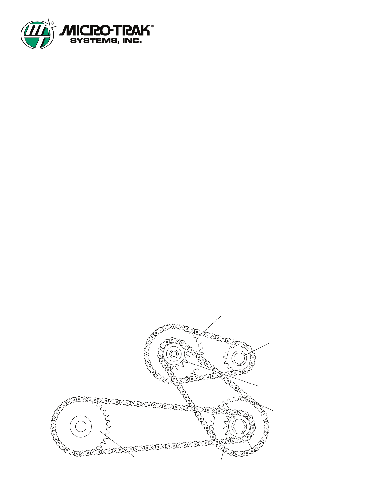
FIRST STAGE DRIVEN
THIRD STAGE DRIVEN
THIRD STAGE DRIVE
SECOND STAGE DRIVEN
SECOND STAGE DRIVE
FIRST STAGE DRIVE
P/N 50289 Rev A • © 2009 • Page 10

Instructions for Micro-Trak
Seed Rate Control Systems
Used with Raven 440/450 Controllers
Installing the Planter Drive
1. Choose a location between row units for the tool bar mount
bracket approximately five inches to the left of a hex shaft
hanger bearing to the center of the tool bar mount bracket.
Mount the bracket to the tool bar using the supplied 1/2”
U-bolt making sure the bracket is square with the tool bar. It
is important to mount the drive assembly as close as possible
to a hex shaft hanger bearing.
2. Mount the motor bracket assembly to the tool bar bracket
using the four 3/8” by 1 1/4” flange bolts. Slide the motor
bracket towards the tool bar as far as it will go and tighten
the flange bolts.
NOTE: Skip step 3 if you are installing a secondary drive
assembly.
3. Mount the hydraulic flow control valve to the motor bracket
using the two 5/16” by 2 3/4” bolts and 5/16” flange nuts. Be
sure the output of the control valve is pointed away from the
tool bar.
4. Install the split sprocket on the hex shaft. Align the hex shaft
sprocket with the outside idler sprocket and tighten.
5. Cut a piece of chain to 23 1/2” and install on inside motor
sprocket and idler sprocket using one of the supplied
connector links. Tighten chain by loosening idler sprocket
and sliding down and retighten.
6. The length of chain required between the outside
idler sprocket and hex shaft sprocket varies by planter
manufacturer and model, so you will need to measure to
determine the length. Cut to length and install using the
supplied connector link.
.062”
7. Loosen the four 3/8” flange bolts installed in step 2.
8. Locate the full threaded 1/2” by 3” bolt, 1/2” jam nut and
1/2” flat washer. Install the flat washer on the bolt and insert
through the tab on the back of the tool bar bracket, thread
the jam nut on and then thread bolt into the motor bracket.
Use this bolt to adjust the chain between the idler and the
hex shaft and tighten the four 3/8” flange bolts.
9. Locate the four SAE #8 male x JIC #8 male straight adapters
and two 90 degree swivel nut elbows and install in both the
“P” pressure and “T” tank ports on the valve mounted on
top of the hydraulic motor. The other two adapters go in
the input and output ports on the control valve. Install the
elbows on the “P” port on valve and output port on control
valve.
10. Locate the 1/2” hose assembly and install between the “P”
port and output port.
11. Locate the SAE #8 male plug and install in the bypass port of
the control valve unless the drive assembly is connected to
an open center hydraulic system.
12. Install the sensor bracket to the motor bracket near the
motor sprocket using on of two 1/4” by 3/4” bolts and flange
nuts.13. Install gear tooth sensor to sensor bracket using the
remaining 1/4” by 3/4” bolt and flange nut and adjust so that
the sensor is pointed directly at the center of the motor shaft
and 1/16” away from the tip of the sprocket teeth.
P/N 50289 Rev A • © 2009 • Page 11
P/N 10221 P/N 12289
P/N 17917
P/N 17918

Instructions for Micro-Trak
Seed Rate Control Systems
Used with Raven 440/450 Controllers
Installing the Planter Drive (cont)
Determine your hydraulic system type before proceeding.
Is it an:
• Open Center System?
• Closed Center System?
• Pressure Compensating
• Closed Center Load Sensing?
From a hose connectivity standpoint, there are just TWO
VARIATIONS in plumbing and are referred to here as either Open
Center or Closed Center configurations.
NOTE: See the illustrations on the following pages for
hydraulic hose plumbing detail for opened and closed
center hydraulic systems as well as single, dual and multi-
drive configurations.
Calculate your Hydraulic Oil Needs
1. What is your Maximum Planting Speed in miles per hour?
MPS = _______
2. What is the closest Desired Seed Spacing in inches?
DSS = _______
3. How many seeds are dispensed per revolution of your Seed
Meter Disc?
SMD = _______
4. What is the Ratio of hydraulic motor revolutions to seed
meter revolutions?
Ratio = _______ to 1
5. What is the Displacement in Cubic Inches of the hydraulic
motor on your planter drive assembly?
CID = _______
EXAMPLE:
MPS = 5
DSS = 6.5
SMD = 30
Ratio = 5.333
CID = 4.9
• (MPS x 5280) x 12) = Inches traveled per hour
((5 x 5280) x 12 = 316800 inches traveled per hour
• Inches traveled per hour ÷ DSS = Seeds per hour
316800 ÷ 6.5 = 48738.46 seeds per hour
• Seeds per hour ÷ SMD = Seed meter revolutions per hour
48738.46 ÷ 30 = 1624.6 seed meter revolutions per hour
• Seed meter revolutions per hour ÷ 60 = Seed meter
revolutions per minute
1624.6 ÷ 60 = 27 seed meter revolutions per minute
• Seed meter revolutions per minute x Ratio = Hydraulic motor
revolutions per minute
27 x 5.333 = 144.4 hydraulic motor revolutions per minute
NOTE: the minimum recommended motor RPM is 30.
• Hydraulic motor revolutions per minute x CID = Cubic inches
of hydraulic oil per minute
144.4 x 4.9 = 707.6 cubic inches of hydraulic oil per minute
• Cubic inches of hydraulic oil per minute ÷ 231 = Gallons of
hydraulic oil per minute
707.6 ÷ 231 = 3 gallons of hydraulic oil per minute
Connecting the Planter Drive Assembly to the Hydraulic System
The hose end fitting required to mate with the supplied adapters
is a #8 JIC 37 degree female.
The recommended hydraulic hose size is 1/2” for both the
pressure and return hoses.
Be sure to route hoses away from pinch points and leave enough
excess length to accommodate folding and unfolding.
Whether you have an open or closed hydraulic system be sure
to turn the oil flow down to about 20% more than calculated
because the excess oil flow means excess heat.
See how to calculate your hydraulic oil needs at the top of this
page.
P/N 50289 Rev A • © 2009 • Page 12
Table of contents
Other micro-trak Control System manuals
Popular Control System manuals by other brands

AMX
AMX Massio MCP-108 quick start guide

Intermatic
Intermatic PJB2175 Installation, operation & service manual

power automation
power automation PA 9000 MC installation instructions

American DJ
American DJ DMX Operator II user manual

V2
V2 WES-EASY manual

Traxxas
Traxxas PRO SCALE 6591 installation instructions

Mitsubishi Electric
Mitsubishi Electric C80 Series instruction manual

Carel
Carel MasterCella Split user manual

TCS
TCS TCS 3000 Operation manual

Wilo
Wilo Geniax Central Control user manual

Solartron Metrology
Solartron Metrology AMETEK ORBIT ACS SI100 manual

Mitsubishi Electric
Mitsubishi Electric AG-150A-A installation manual