MicroART Kes DOMINATOR MPPT 200/60 User manual
Solar Energy
Controller
MPPT SEC
Wind Energy
Controller
WEC
USER’S MANUAL

3
USER'S MANUAL
CONTENT
INTRODUCTION 4
GENERAL DESCRIPTION AND FEATURES 4
TECHNICAL SPECIFICATIONS 5
SAFETY PRECAUTIONS 7
CONTROLLER PLACEMENT AND INSTALLATION 9
CONTROLS AND INDICATION 10
WIRE DIAGRAM OF THE CONTROLLER CONNECTION 12
FIRST START, PRESTARTING PROCEDURES 13
USER SETTINGS EDITING 15
“SETTINGS”MODE 17
APPENDIX 26
APPENDIX 1. MANUAL OPERATING MODE 26
APPENDIX 2. EXTERNAL CURRENT SENSORS. CONNECTION AND CALIBRATION 26
APPENDIX 3. FIRMWARE UPDATE 29
APPENDIX 4. CONTROLLER OPERATING WITH WIND TURBINE 29
APPENDIX 5. GENERAL RECOMMENDATIONS FOR OPERATION AND CONNECTION OF THE CONTROLLER, SP AND OTHER EQUIPMENT 35
WARRANTY LIABILITIES 40
REPAIR 41

INTRODUCTION
The present manual sets out safety standards, installation process and settings of the device and related system components. This manual is for use by any
qualied personnel who plan to install the device and related system components. Some connection and setting work should be carried out by qualied
personnel only in cooperation with local energy supplier or authorized dealer. We strongly recommend the installation, commissioning, maintenance and
repair carried out by well qualied personnel only.
4
GENERAL DESCRIPTION AND FEATURES
The solar controller SEC is a MPPT controller (hereinafter referred to as the "controller") of the Accumulator battery charge (hereinafter referred to as "AB")
from the solar panels array (hereinafter referred to as "SP"), with the tracking of the maximum power point (MPPT). This product has many important advan-
tages, namely:
Eciency up to 98% allows not only to collect all solar energy practically without losses, but also makes it possible to avoid using cooling fans: it signicant-
ly increases the reliability of device.
High performance, and therefore up to 10% higher eciency (compared to some 3rd party MPRT controllers) and up to 40% compared
to PWM controllers.
The allowable input voltage limit of the controller is 200 V (or 250 V - depending on the modication), therefore the array of solar panels may consist of up
to 3 (or 4) solar panels with 24 V rate, connected in series (open circuit voltage of each one - without load - can reach 45 V at temperature + 25C°, which is in
total 3 * 45 = 135 V, or 4 * 45 = 180 V).
Two current Hall Eect sensors (which is much better than a shunt) for monitoring of charging/discharging by other device (for example, by a wind turbine
and/or from an inverter) - are optional.
The current sensors make possible to cooperate with a hybrid inverter onto the AC grid of 220 V: it allows to add current instantly in AB bypass. It may be
even greater than AB allowed charge current; anyway, the use of AB with a minimum capacity is necessary. It concerns any ordinary inverter: power addition
to the load by use of SP without AB charge wasting. This option is very important as the energy can go“in transit”. AB are not wasted, and therefore, they serve
much longer.
Own transformer-based power supply from the SP allows to feed the controller regardless the battery state. Operation is possible even with fully discharged
battery, at a minimum voltage.
Counter of incoming A*h / W*h.
Ability to update the rmware in the ash-memory.
The controller allows to set manually any non-standard voltage for working with AB (besides 12/24/48/96V). It is useful for non-standard alkaline batteries,
or batteries with a non-standard number of cells.
Peak current (up to 100A or 60A depending on the modication) and the ability to operate in 96V systems, allows to obtain the peak power from one
controller: up to 11kW (current 100A is multiplied by the AB buer voltage 110V).

5
TECHNICAL SPECIFICATIONS
The possibility to connect lithium-iron-phosphate (LiFePO) batteries with BMS. The controller manages BMS or, if necessary, automatically transfers the
control to the MAC inverter (the controller is connected by additional cable to MAC, and MAC can control the BMS).
Three programmable powerful relays for external devices control: for example, in complete autonomy, it is possible to turn othe refrigerator automatically
for the night by keeping more ice or cold accumulator in the freezer for energy saving. Unlike competitors, SEC DOMINATOR and PRO have the powerful relay
of 3.5kW - 240V 16A (i.e. it is possible to connect, for example, a refrigerator, directly through the controller, without any supplementary relays). Temperature
compensation and charging mode correction extend the battery life.
Three stage buer charge.
Tropicalized construction: the controller board is protected by a waterproof coating (varnish), which minimizes the harmful eect of a high humidity and
insects.
Possibility of remote monitoring with“MALINA”Appliance.
The controller also can be used to charge battery from wind turbine.
Battery voltage
Maximal charging current
Maximal power of PV array
Maximum voltage of the open PV array
Minimum voltage of PV array
Maximum operating voltage of PV array
Power consumption in standby mode
Full load eciency
12 / 24 / 36 / 48 / 96V Automatic selection (you can manually set any voltage in the range
12 – 96V)
100A @ 40°C / 60@ 40°C (depending on model)
12V: 1350W / 24V: 2750W / 48V: 5500W / 96V: 11KW (for the model 200/100)
12V: 810W / 24V: 1650W / 48V: 3300W / 96V: 6.6KW (for the model 200/60 and the model 250/60)
200V (for models 200/60 and 200/100)
250V (for the model 250/60)
Battery voltage plus 5V for start,
Battery voltage plus 1V for operation
12V: 95% / 24V: 96,5% / 36V: 97% / 48V: 98% / 96V: 99%
185V (for the models 200/60 and 200/100)
233V (for the model 250/60)
Not more than 1.9 W
ATTENTION! The use of additional equipment is necessary for the cooperation of the controller and wind turbine! More information about operating
with wind turbine can be found in Appendix №4.

6
AB type
Temperature sensor
Temperature compensation (default)
Programmable relay
Communication port
Protection
Operating temperature
Cooling
Humidity (without condensation)
Terminals size
Body material, color
Protection class
Installation
Ability to work onto AC network in pair with the hybrid invert-
er (current addition by request, including greater than
allowed by AB)
Yes (with MAC or with current sensor (optional), in the case of an outdated MAC model,
or an external third-party inverter)
Yes (optional, with current sensor)
RS-232, USB
From -25°C to 60°C with decreasing output current at temperature inside the body is
above 65°C
Passive
Aluminum / steel
IP30
Vertical wall mount
35 mm²/ AWG2
95%
Protection from overheating (power is reduced with temperature rising), short circuit PV
and reverse polarity protection. Protection against battery reverse polarity
GEL, AGM, sealed, ooded, alkaline, LiFePO(BMS is required)
Internal
-3mV / °for 2V battery cell
3 pcs DPST AC: 240V / 16A
The ability to monitor currents from third-party devices
(inverter, wind turbine)
SAFETY PRECAUTIONS
This manual contains important safety instructions that must be followed when installing and operating the device. Read this manual and save it for the
further use. Before starting the installation, operation or maintenance, please read the rules and become familiar with the device. In this manual and on the
product body, the special signs and notices are used. They warn of potential danger or draw attention to information that claries or simplies the operation.
7
Weight, kg 3.7 (for the model 200/60)
5 (for the models 200/100 and 250/60)
240 x 125 x 190 (for the model 200/60)
360 x 125 x 210 (for the models 200/100 and 250/60)
Dimensions, mm
The controller allows you to update its ash-memory rmware. Details are given in Appendix 3.
The main dierence between version 6.0 and previous versions is the modication in the control interface and indication algorithms.
ATTENTION! This manual is valid for rmware version 6.0 and higher. If you are using a device with an earlier rmware version, we recom-
mend you update it to the latest or use earlier versions of the user manual.
IMPORTANT SAFETY INSTRUCTIONS.
STUDY, SAVE AND STRICTLY FOLLOW!
This sign is used together with a warning notice "Danger" or "Warning", or instead of it and means that violation of the requirements may cause
an electric shock.
This is a sign of warning. It is used to draw an attention to the potential danger of personal injury or essential property damage. Follow all the require-
ments listed after this sign. Violation of the requirements may cause a damage to equipment and injury or death.

8
ATTENTION! Dangerous voltages are possible in the system!
The installation and all connections should be done by well qualied personnel only.
ATTENTION! If the controller is connected to both the solar panels (SP) and AB (especially when the charge with SP is going on) it is
forbidden to disconnect the controller from the AB. This can lead to the controller damage, which is not covered by warranty. For the
same reason, it is forbidden to install a circuit breaker between the controller and the battery or, if necessary, it must have a large
current reserve relative to the controller current (at least 150% of the controller's maximum current).
SAFETY REQUIREMENTS:
1. Before using the controller please study all the instructions and warning labels on your device and batteries, as well as all the relevant chapters
of this manual.
2. The use of accessories which are not recommended or not supplied by the manufacturer may cause a risk of re, electric shock or injury.
3. Make sure that existing wiring is in a good condition and has a proper sectional area to avoid the risk of re and electric shock. Do not connect the controller
to a damaged or defective wiring, as well as defective electrical equipment.
4. In the case of any failure of the inverter please don't use it.
5. This device contains no user serviceable parts. Do not disassemble the inverter, except when it is directly mentioned for wire and/or cables connection. Inside
repair may cause a risk of electric shock or re. Internal capacitors remain charged after power is switched ocompletely.
6. Before maintenance, cleaning or working with any components connected to the controller please disconnect the inverter from AC and DC sources to reduce
the risk of electrical shock. Standby mode of the device does not reduce the risk.
7. The device must be protected from rain, snow or any liquids. Operating in a humid environment shorten the product lifetime. The warranty does not cover
the corrosion caused by high humidity.
8. To avoid the risk of short-circuit use always the tools with insulated handles while installing or working with this equipment.
9. When working with electrical equipment please take ometal items, such as rings, bracelets, necklaces, watches, etc.
10. It is necessary to observe polarity of the AB strictly when attaching to the controller. Incorrect connection leads to controller damage. In this case the repair-
ing will not be covered by warranty.
11. It is necessary to observe the temperature conditions and humidity during operating.
12. Do not place the controller in dusty environments.
13. It is not allowed to use the converter for other purposes, the same as to exceed the recommended operating parameters.
14. If AB are not sealed, they should be placed in a ventilated room.
15. It is necessary to prevent the access of children, animals and unskilled personnel to the controller and battery.

When choosing a controller placement, it is necessary to follow the re safety regulations and electrical equipment and accumulator batteries
operating rules.
The controller must be installed in a dry and well-ventilated place. The controller should be placed as close to AB as possible and connected by conductors of
the required sectional area. The conductors must withstand the expected charging current of your system. It is not recommended to make AB connection
conductors more than 3 m long to avoid a large voltage loss. When longer cables are required it is necessary to increase their sectional area by 2-3 times.
It is necessary to install the temperature sensor on one of the AB sides and x it securely.
Watch this restriction especially when installing the system in places where high solar radiation and low temperatures may occur. Approximately, the voltage
of the open SP circuit increases by 20-25% at -30°C, i.e. the solar panel with 45 V open circuit voltage at + 25°C, will generate 55V at -30°C.
The required sectional area of SP conductors depends on the array capacity and its voltage. The best eciency is achieved when the input voltage
of the controller is twice the battery voltage.
The controller is wall-mounted. Installation should be done on a vertical surface (wall) with free space of at least 15 cm from the sides and at least 25 cm from
the top. Otherwise, the controller may become overheated, what reduces the generated power.
To mount the product please x 4 screws of proper size in the wall according to the drawings and x the product on them.
9
CONTROLLER PLACEMENT AND INSTALLATION
ATTENTION! The input voltage of the controller connected to the solar panels array should never exceed 220V/250V (depends on model).
The controller can be damaged by input voltage surplus which is not covered by warranty.
For the cables connecting please remove the bottom cover by unscrewing the 4 screws at the bottom of the body, cut the required size holes through the
rubber gaskets, pass the cables through them and put the cover back. The description of the connectors and the recommended wiring diagrams are given
below in the description.
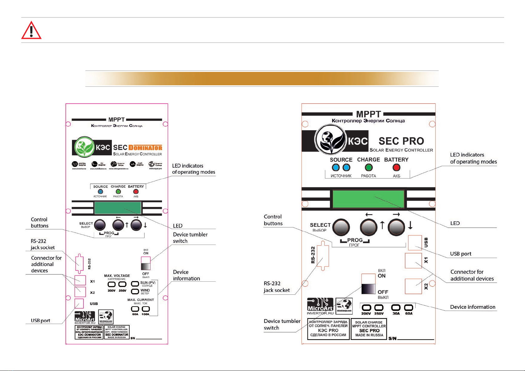
The appearance and location of the control devices of DOMINATOR model line are shown in Picture 1, of PRO model – in Picture 2.
10
CONTROLS AND INDICATION
Picture 1.Exterior view of SECDOMINATOR controller. Picture 2. Exteriorview of SECPRO controller.
ATTENTION! The height of each screwed screw from the wall surface should be no more than 5-6 mm, otherwise the controller internal com-
ponents may be damaged.
For the cables connecting please remove the bottom cover by unscrewing the 4 screws at the bottom of the body, cut the required size holes through the
rubber gaskets, pass the cables through them and put the cover back. The description of the connectors and the recommended wiring diagrams are given
below in the description.
The appearance and location of the control devices of DOMINATOR model line are shown in Picture 1, of PRO model – in Picture 2.
10
CONTROLS AND INDICATION
Picture 1. Exterior view of SEC DOMINATOR controller. Picture 2. Exterior view of SEC PRO controller.
ATTENTION! The height of each screwed screw from the wall surface should be no more than 5-6 mm, otherwise the controller internal com-
ponents may be damaged.
Modes and operational parameters are displayed by the LCD and 3 LEDs:
“SOURCE” (Blue LED) – indicates the input voltage level (the state of SP). If the SP voltage exceeds AB voltage for more than 5V then the LED is constantly on.
When the dierence is more than 1-5V - then the LED is blinking. But when SP voltage is below AB voltage plus 1V then the LED is OFF.
“CHARGE” ((Green LED) – indicates AB charge mode. For cyclic charge (charge by maximum current) the LED is constantly ON.
In absorption charging mode the LED blinks evenly.
In the modes of equalization and charge maintaining the LED blinks seldom.
“Battery” (Red/Green LED) – indicates AB charge level.
The LED changes its color in 2-second period. The higher AB charge is the longer the LED is green and the remainder of period (the rest from 2s) it is red.
Thus, when AB is fully charged the LED is constantly green; if AB is half charged then the light is green/red changing one after another; for discharged AB the
light is constantly red.
LCD display has 2 rows of 16 characters each and is served for displaying the current parameters and user settings input.
11
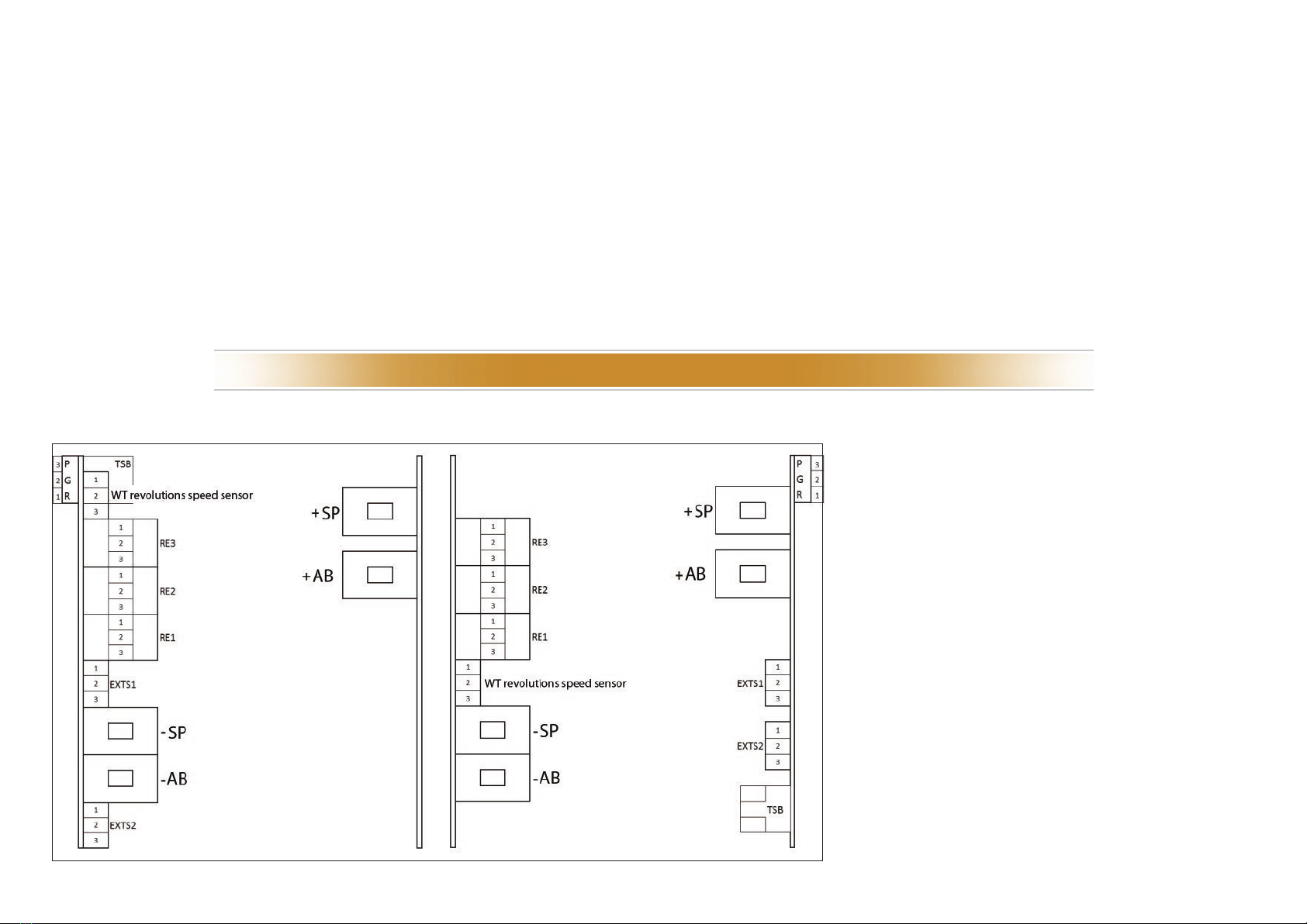
CONNECTION PORTS
View of the connectors for DOMINATOR model
Picture 3.
View of the connectors for PRO model
Location and purpose of controller connecting ports are shown in Pic. 3 (The bottom view is shown with the bottom cover is removed):
"–SP" – SP minus wire terminal;
"+SP" – SP plus wire terminal;
"–AB" – AB minus wire terminal;
"+AB" – AB plus wire terminal;
TSB – AB temperature sensor connector (a wired
temperature sensor is connected to this receptacle.
It can be found inside the box)
RE1...RE3 – auxiliary relays for additional control of
external devices;
For all relays:
Pin 1– normally closed (NC);
Pin 2 – common (COM);
Pin 3 – normally open (NO);
EXTS1 –External current sensor 1 (hereinafter
referred to as ECS 1);
EXTS2– External current sensor 2 (hereinafter
referred to as ECS 2);
"P G R" — Mini DIP switch for some setting of
connection between several controllers and MAC.
Modes and operational parameters are displayed by the LCD and 3 LEDs:
“SOURCE” (Blue LED) – indicates the input voltage level (the state of SP). If the SP voltage exceeds AB voltage for more than 5V then the LED is constantly on.
((Green LED) – indicates AB charge mode. For cyclic charge (charge by maximum current) the LED is constantly ON.
In absorption charging mode the LED blinks evenly.
In the modes of equalization and charge maintaining the LED blinks seldom.
“Battery” (Red/Green LED) – indicates AB charge level.
The LED changes its color in 2-second period. The higher AB charge is the longer the LED is green and the remainder of period (the rest from 2s) it is red.
Thus, when AB is fully charged the LED is constantly green; if AB is half charged then the light is green/red changing one after another; for discharged AB the
light is constantly red.
LCD display has 2 rows of 16 characters each and is served for displaying the current parameters and user settings input.
11
CONNECTION PORTS
View of the connectors forDOMINATOR model
Picture 3.
View of the connectors for PRO model
Location and purpose of controller connecting ports are shown in Pic. 3 (The bottom view is shown with the bottom cover is removed):
"–SP" – SP minus wire terminal;
"+SP" – SP plus wire terminal;
"–AB" – AB minus wire terminal;
"+AB" – AB plus wire terminal;
TSB – AB temperature sensor connector (a wired
temperature sensor is connected to this receptacle.
It can be found inside the box)
RE1...RE3 – auxiliary relays for additional control of
external devices;
For all relays:
Pin 1– normally closed (NC);
Pin 2 – common (COM);
Pin 3 – normally open (NO);
EXTS1 –External current sensor 1 (hereinafter
referred to as ECS 1);
EXTS2– External current sensor 2 (hereinafter
referred to as ECS 2);
"P G R" — Mini DIP switch for some setting of
connection between several controllers and MAC.
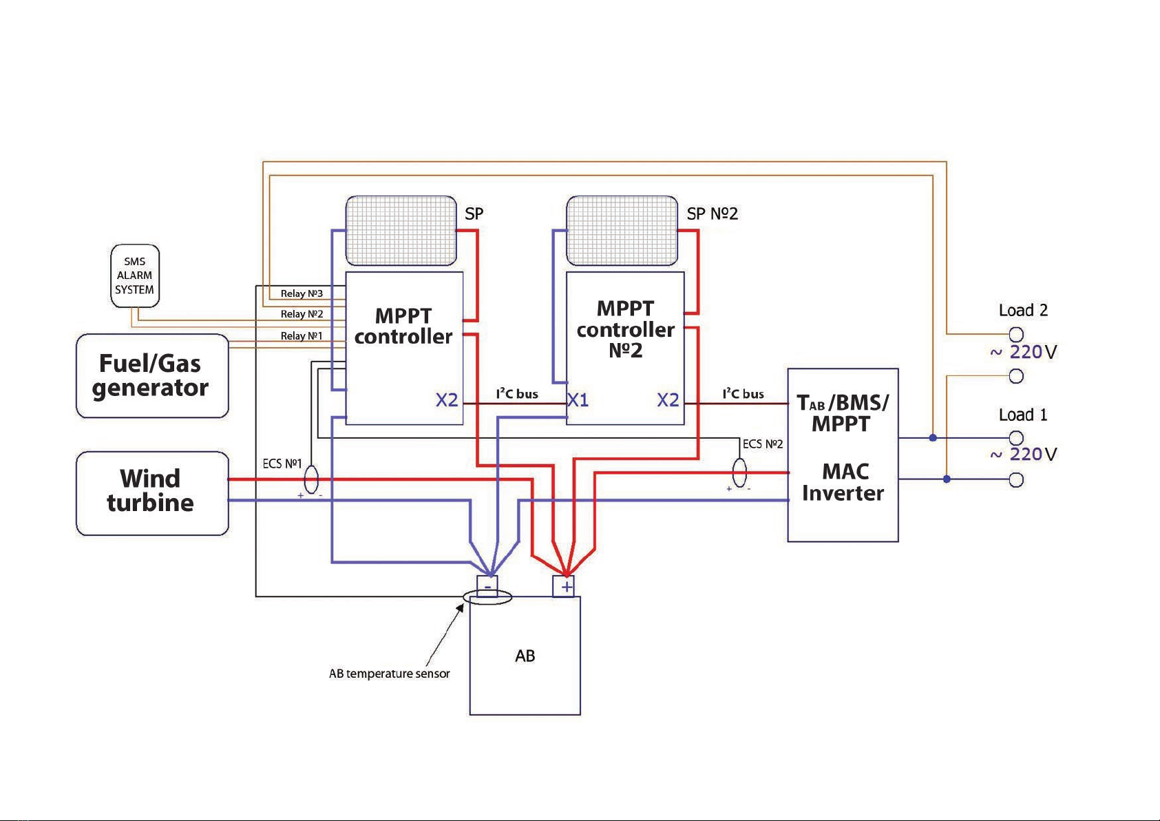
The recommended wire diagram of the controller connection is shown in Picture 4 (the use of current sensors and control relays is not necessary):
12
Picture 4
WIRE DIAGRAM OF THE CONTROLLER CONNECTION
The recommended wire diagram of the controller connection is shown in Picture 4 (the use of current sensors and control relays is not necessary):
12
Picture 4
WIRE DIAGRAM OF THE CONTROLLER CONNECTION
The use of external current sensors ECS1 and ECS2 allows the controller to count the additional external charging/discharging currents coming from the
inverter and/or the wind turbine. This gives an opportunity to reduce charging current automatically when AB is being charged by both wind turbine and
solar panels and charging current exceeds the maximum allowed AB current. Also, the use of ECS2 for the control of charging/discharging inverter currents
allows if needed to add instantly the charging current from the solar panels to the inverter (for the load) even when AB are fully charged and the controller is
in trickle charge mode (high current is not allowed for AB at the end of charge).
You should consider that communication via I²C bus is available ONLY with MICROART equipment and connecting cable supplied with the controller set! At
the same time, there is no need in ECS2 sensor (MAC inverter transmits its data on currents via I²C bus). If the sensor duplicates the I²C data from the MAC, the
controller will produce incorrect charge currents.
Note. The rst press on a button activates LCD backlit if it is oand only then the chosen function is activated.
Enter the controller menu and scroll it by arrow buttons then select the submenu “AB settings” enter it and the controller will set working voltage
automatically.
1| Follow the polarity to connect the controller to AB (rstly without SP) and switch on the device by a tumbler switch.
2| Choose the interface language: Russian or English.
3| Set the battery voltage.
13
FIRST START, PRESTARTING PROCEDURES
ATTENTION! When I²C connection is used between MAC and controller then the ESC2 sensor should be disconnected!
ATTENTION! If the controller has AB factory settings 12V as an example, and the user connects 24V or 48V AB then the device will beep and
display: "Battery overvoltage".
In this case, you must go to the controller menu and enter your own settings. To go to the setup menu, you must press long two buttons:
“SELECT” and “ ”("LEFT/UP").
Voltage
12V? Yes No
AB

4| Switch the controller o.
5| Connect the SP array.
6| Connect the AB temperature sensor and place it on your battery.
7| If necessary, calibrate (see the relevant chapter of the manual) and connect ECS1 and ECS2.
8| Connect the loads and/or the alarm system to the external devices control relay if necessary.
9| In case you have an additional equipment like MAC inverter and/or BMS from MICROART or additional controllers, please connect the devices via I²C
bus using the connecting cable supplied with controller and make the necessary settings.
10|Turn the controller on.
11|Make your system parameters settings using control buttons.
12|Controller is ready for operating.
To conrm, press "Left / Up" (i.e. the button that is located under the text "Yes"), to cancel the proposed option, press "Right / Down" (the button located under
the sign "No"). In case of failure, the user must set all voltages manually.
To conrm the oered option, it is enough to set AB type, capacity and charging current - charging voltages will be set automatically. But in this case, the user
has an opportunity to edit voltages (by selecting the corresponded submenu item).
Check up the parameters (by scrolling the controller menu), which are set automatically. Compare them with the AB and solar panels passport data and if
necessary, adjust. Check up the voltage thresholds in the menu.
14
ATTENTION! If you made a mistake during the setup, the controller starts to beep continuously, which means that you need to adjust the
settings or the connection. You can also reset the controller to the factory default settings (use the proper menu section) and repeat the
setup.

The "Indication" mode is the main operating mode. The screen on several pages displays the information about all the basic parameters of the device. Below
is a detailed description of the parameters displayed in the "Indication" mode:
Page 1 contains the following information:
All settings (including ECS calibrations) are stored in a non-volatile memory (NVRAM) and they don't depend on the power switch position. When you change
the parameter values, after conrming it takes eect immediately.
Control and indication algorithms are extremely close to the MAC inverter ones.
The controller has two modes:
“Indication”- the main operating mode, the information about all device operating parameters are displayed on the screen on several pages.
“Settings”- the mode where all device parameters are set up and all calibrations can be done.
Enter/Exit“Settings”mode can be done by long pressing two buttons:
"SELECT" and " " ("Left/Up").
By LONG pressing (from 0,5 to 2 sec) the button“SELECT”you can enter submenu, start editing and conrm the action.
The menu navigation, sections browsing and settings selection can be done by a short pressing (less than 0.5 seconds) the buttons "Left / Up" and "Right / Down".
The parameter values can be changed as follows:
Right button " " selects the desired digit, and the central button " " the desired value (values are cycled from 0 to 9).
To exit the settings submenu scroll it to the "Exit" then conrm the action by a LONG pressing the "Select" button.
15
USER SETTINGS EDITING
“INDICATION” MODE
1– AB charge indicator:
"i" – cyclic charge mode;
"v" – absorption charging mode;
"B" – initial buer charge mode (balancing);
"b" – secondary buer charge mode (charge
level maintenance);
"S" – scan mode (search for the maximum
power point).
2– Indicator of Excess/Shortage of power generated by the SP to
maintain the necessary charge/load current:
"+" – Lack of input power (requires to "add" the power);
"—" – excess of input power (requires to "reduce" the
power);
"=" – the load power is equal to the input power.
3 – "Sol" – the parameters of SP;
4– SP current in amperes;
5– SP voltage in volts;
6– indicator of the operating point position (OP)
relative to the maximum power point (MPP):
"R" – PT on the right of MPP;
"L" – PT on the left of MPP;
"O" – PT is in MPP.
7– "AB" – parameters of AB / load;
8– total AB and load current in amperes;
9– AB voltage in volts.
i
+
0
.
0
0
0
.
0
0
0
.
0
0
/
R
.
0
0
0
/
1 2 3 4 5
6 7 8 9
1| PAGE 1 Sol
AB
V
V

Page 2 contains information on the currents measured by external current sensors:
Page 3 contains information on power:
Where:
1– current measured by an external current sensor 1;
2– power measured by an external current sensor 1 (Is dened as the multiplication of voltage by AB current measured by the external current sensor 1);
3– current measured by an external current sensor 2;
4– power measured by an external current sensor 2 (Is dened as the multiplication of voltage by AB current measured by the external current sensor 2).
Where:
1– output power of the controller: W;
2– power generated by the SP: W;
3– Power generated by an alternative energy source (Wind turbine). The alternative source is connected through external current sensor 1 (Optional).
Where:
1– internal controller temperature;
2– AB temperature.
When the battery temperature sensor is disconnected, the temperature is set equal to 25 deg. In this case, the absence of a temperature sensor is indicated by a ashing "+25".
16
2| PAGE 2
1 2
3 4
0
.
0
/
0
W
0
.
0
0
0
/
0
W
Page 4 contains information on temperature:
4| PAGE 4
1 2
3| PAGE 3
1
2 3
0
W
0
W
/
0
W
P
o
u
t
P
i
n
Page 5 contains the information on the energy drawn during the last 24 hours:
Note: in 4 hours of the dark period these values will be reset to zero. (They are reset also by “Malina” appliance at 23:59, to avoid them to be counted on next day).
Where:
1– drawn energy kW*h;
2– drawn energy kW*h (thousands).
The total energy in kWh is calculated as: (number 1) + (number 2) / 1000.
5| PAGE 5
1 2
,
S1
S2
Temperature,°C
Day energy
Intrn, +25 AB, +25
kW*h

“Settings” mode – is a mode where all device operating parameters are set and all needed calibrations can be done. By selecting that mode, you enter the
setting menu which consists of the following submenus:
1. AB settings
2. MAC/BMS/ MPPT connection
3. Factory settings
4. Calibration
5. Display settings
6. Indication
7. Operation modes
8. Source settings
9. Threshold voltages
10. Relay settings
To exit the submenu, you should scroll it to the "Exit" (each submenu has it) and a LONG pressing the button “Select”will conrm the action.
When you change a parameter value, the new value takes eect immediately.
Below you can nd the detailed description of each menu section.
1.1“Type” – type of used AB, there are 6 options available:
1. "Acid" – Lead-Acid battery with liquid electrolyte;
2. "Gel/AGM" – Gel or standard AGM AB;
3. "AGM-Shoto" – AGM AB produced by "Trojan Shoto";
4. "AcidTrojan" – acid AB produced by "Trojan";
5. "Li-Ion 3.9" – Lithium-ion battery with a voltage of 3.9V per cell;
6. "Li-Ion 3.7" – Lithium-ion battery with a voltage of 3.7V per cell;
Type of input – "Option selection".
1.2. “Capacity” - overall capacity of AB connected in parallel –
ampere-hours.
1.3. «The cyclic charge voltage» – maximum AB voltage (V) to be switched
over to maintaining AB voltage mode. Type of input – "Numeric".
1.4. “The buer charge voltage” – voltage (V) of primary charge equaliza-
tion. Type of input – "Numeric".
1.5. “The charge initial voltage” – voltage (V) below which the controller
starts AB charging. Type of input – "Numeric".
1.6.“Maximum charge current” – maximum allowed AB charge current (A).
Type of input – "Numeric".
1.7. "Temperature coecient" – AB voltage temperature coefficient, in mV
per cell. Type of input – "Numeric".
17
“SETTINGS” MODE
ATTENTION! For Li-Ion AB charge at subzero temperatures is prohibited!!!
1| “AB SETTINGS”
All data on used AB are in that section.

To charge alkaline batteries by means of MPPT Pro controller you must do the following:
1. Select the required AB voltage (12, 24, 48, 96) V.
2. 2. Calculate the required number of cells in series connection (Nc) to achieve the required AB voltage.
For example, for KGL cell type the charge voltage is 1,44 V at 25C (degrees Celsius). In that case the number of cells in series connection (Nc) will be equal to
10, and cycle charge voltage will be 14,44 V.
3. Set in the controller AB type –“Acid”.
4. Set the cyclic charge voltage manually.
5. Set the real AB system capacity.
6. Set the cyclic charging rate manually equal to 0,2C. For systems of more than 500 Ah capacity the value of the cycle charge current is limited by 99A.
7. Calculate the temperature coecient by multiplying the temperature coecient from alkaline batteries passport by Nc and divide it by K, where K is:
6 – for 12V system;
12 – for 24V system;
24 – for 48V system;
48 – for 96V system;
8. You should set in the controller the nearest integer value of the temperature coecient.
This submenu contains all necessary settings for other devices connection for a complex system.
7 choices for complex system are available:
1. Controller+MAC;
2. Multiple controllers+C;
3. Controller+C+BMS;
4. Multiple controllers+C+BMS;
5. Controller+BMS;
6. Multiple controllers;
7. Multiple controllers+BMS.
When you have a MAC in the system (options 1 and 2), the Controller (or all controllers - if there is a number of them) should be set in“Slave/MAC”mode.
For the system without MAC but with BMS (option 5) the Controller should be set as“Master MPPT+BMS”.
For the system without MAC and with a number of controllers (option 4) – one of the Controllers should be set as“Master MPPT”, the others – as “Slave/MAC”.
For the system without MAC and with a number of controllers plus BMS (option 3) – one of the Controllers should be set as“Master MPPT+BMS”, the others –
as“Slave/MAC”.
18
2| “MAC/BMS/MPPT CONNECTION“

To interconnect the devices, you need to use 6-core at cables both sides terminated by RJ12 jack plugs according to the scheme of direct connection
Pin-to-Pin.
1. “Slave” – connection to MAC in“Slave” mode.
This connection mode can be used either for Controller working with MAC or without MAC but in the group of controllers operating in parallel for one AB
pack. In this mode, all three switches "P G R" should be in OFF position.
2. “Master MPPT” – connection to the other controllers in“Master” mode.
This connection mode serves for the Controller operating without MAC in a group of several Controllers connected in parallel to one AB pack. This mode must
be set only for one Controller.
In this mode, all three switches "P G R" should be in ON position.
3. "Master MPPT+BMS" – the connection with other Controllers and BMS in“Master”mode.
This connection mode serves for either Controller operating without MAC or its operating in a group of several Controllers in parallel connection without MAC
to one AB pack with a BMS system. Only one controller can be set in this mode. For this mode, all three switches "P G R" should be in ON position.
19
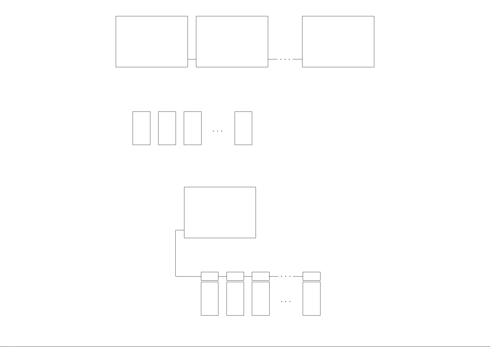
Pic.1. Scheme of the system "Multiple Controllers + MAC+ BMS".
2.1. “DIRECTION” – a selection of MAC, BMS and other MPPT connection:
For the slave device, the number which is set here represents its address.
For master device – the total number of controllers in the system minus one. Therefore, the combination of "Master MPPT" with zeroed "Address selec-
tion/Number of slave MPPT" is incorrect. Type of input - "Numeric".
2. 2. "ADDRESS SELECTION/NUMBER OF SLAVE MPPT" – number of controllers operating in parallel for one AB pack.
The order of connections and
required settings are shown in
the pictures 1-5. Controller 0
“Direction”
“Address selection
Number of slave MPPT”
“00”
X1
BMS
AB1
X2
”Slave”
Controller 1
“Direction”
”Address selection
Number of slave MPPT”
“01”
X1 X2
”Slave”
Controller N
“Direction”
Address selection
Number of slave MPPT”
“N-1”
TAB/BMS/MPPT
MODEM
“TAB/BMS”
X1 X2
”Slave”
BMS
AB2
BMS
AB3
BMS
ABM MAC

20
Pic. 2 . Scheme of the system "Multiple Controllers + MAC".
Pic. 3. Scheme of the system "Multiple Controllers + BMS".
Controller 0
“Direction”
“Address selection
Number of slave MPPT”
“00”
X1
BMS
AB1
X2
”Slave”
Controller 1
“Direction”
”Address selection
Number of slave MPPT”
“01”
X1 X2
”Slave”
Controller N
“Direction”
Address selection
Number of slave MPPT”
“N-1”
X1 X2
”Master MPPT+BMS”
BMS
AB2
BMS
AB3
BMS
ABM
Controller 0
“Direction”
“Address selection
Number of slave MPPT”
“00”
X1
AB1
X2
”Slave”
Controller 1
“Direction”
”Address selection
Number of slave MPPT”
“01”
X1 X2
”Slave”
Controller N
“Direction”
Address selection
Number of slave MPPT”
“N-1”
TAB/BMS/MPPT
MODEM
“TAB/BMS”
X1 X2
”Slave”
AB2 AB3 ABM MAC
21
Pic. 4. Scheme of the system "Multiple Controllers".
Pic. 5. Scheme of the system "Controller + BMS".
Controller 0
“Direction”
“Address selection
Number of slave MPPT”
“00”
X1
BMS
AB1
X2
”Master MPPT+BMS”
BMS
AB2
BMS
AB3
BMS
AB M
Controller 0
“Direction”
“Address selection
Number of slave MPPT”
“00”
X1
AB1
X2
”Slave”
Controller 1
“Direction”
”Address selection
Number of slave MPPT”
“01”
X1 X2
”Slave”
Controller N
“Direction”
Address selection
Number of slave MPPT”
“N-1”
X1 X2
”Master MPPT”
AB2 AB3 ABM
This manual suits for next models
2
Table of contents


