Microdyn Nadir AQUADYN FZ50 Hollow User manual

AQUADYN® FZ50 Hollow
Fiber Module
Operation Manual

AQUADYN® FZ50 Series Hollow Fiber Module | OPERATION MANUAL
MICRODYN-NADIR | REVISION: B | DATE: 01/08/2020
2
Contact
Europe
Germany: +49 611 962 6001
Italy: +39 0721 1796201
info@microdyn-nadir.com
Americas
USA: +1 805 964 8003
Brazil: +55 11 3378 7500
info@microdyn-nadir.com
Asia
China: +86 592 677 5500
Singapore: +65 6457 7533
infochina@microdyn-nadir.cn

AQUADYN® FZ50 Series Hollow Fiber Module | OPERATION MANUAL
MICRODYN-NADIR | REVISION: B | DATE: 01/08/2020
3
Table
of Content
1Introduction.............................................................................................................................5
2Handling & Storage............................................................................................................6
2.1
SAFETY INSTRUCTIONS
.............................................................................................................................6
2.2
PRESERVATIVE SOLUTION
........................................................................................................................6
2.3
HANDLING
......................................................................................................................................................6
2.4
STORAGE
.......................................................................................................................................................6
3Installation............................................................................................................................7
3.1
DISASSEMBLING
..........................................................................................................................................7
4Operation.............................................................................................................................8
4.1
START-UP
......................................................................................................................................................8
TABLE 1. RECOMMENDED START-UP FLOWS & FILTRATION TIMES.
............................................................8
4.1.1 Preservative & Air Purge..........................................................................................................................................8
4.2
STANDARD OPERATING CONDITIONS
....................................................................................................8
TABLE 2. STANDARD OPERATION CONDITIONS FOR VARYING FEED WATER TURBIDITIES.
.................8
4.3
OPERATION
...................................................................................................................................................8
4.3.1 Feed pH.......................................................................................................................................................................9
4.3.2 Feed Temperature......................................................................................................................................................9
4.3.3 Turbidity Level ...........................................................................................................................................................9
4.3.4 Membrane Flux...........................................................................................................................................................9
4.3.5 Flow Rate ....................................................................................................................................................................9
4.3.6 Transmembrane Pressure (TMP) ............................................................................................................................9
4.3.7 Backwash....................................................................................................................................................................9
4.3.8 Flushing ......................................................................................................................................................................9
5Backwash ..........................................................................................................................10
5.1
BACKWASHING WATER
............................................................................................................................10
5.2
BACKWASHING CONDITIONS
..................................................................................................................10
5.3
BACKWASHING PROCEDURE
.................................................................................................................10
5.4
PERIODICAL STERILIZATION (AT TIME OF OPERATION)
...................................................................10
6Offline Treatment..............................................................................................................11

AQUADYN® FZ50 Series Hollow Fiber Module | OPERATION MANUAL
MICRODYN-NADIR | REVISION: B | DATE: 01/08/2020
4
6.1
SHORT-TERM STORAGE (2 DAYS OR LESS)
........................................................................................11
6.2
SHORT-TERM STORAGE (3-7 DAYS)
......................................................................................................11
6.3
LONG-TERM STORAGE (LONGER THAN 7 DAYS)
...............................................................................11
7Chemical Cleaning...........................................................................................................12
7.1
CHEMICALS USED FOR CLEANING
........................................................................................................12
7.1.1 Type of Chemical & Target Contaminants...........................................................................................................12
TABLE 3. RECOMMENDED CLEANING CHEMICALS FOR AQUADYN® FZ50 MODULES.
..........................12
7.1.2 Conditions of Chemical Cleaning .........................................................................................................................12
7.2
CLEANING PROCEDURE
...........................................................................................................................12
TABLE 4. STANDARD CHEMICAL CLEANING PROCEDURE OF AQUADYN® FZ50 MODULES.
................13
7.2.1 Cleaning Steps.........................................................................................................................................................15
7.2.2 Measuring the Flux..................................................................................................................................................17
TABLE 5. WATER TEMPERATURE CONVERSION TABLE (CONVERSION TO WATER TEMPERATURE
25°C).
..........................................................................................................................................................................18
7.3
FREQUENCY OF CHEMICAL CLEANING
................................................................................................18
8Return Shipment...............................................................................................................19
9Disposal of the Module....................................................................................................20
10 Appendix............................................................................................................................21
10.1
DIMENSIONS OF AQUADYN™ FZ50-AC-FUC1582 MODULE
...............................................................21
10.2
CUT-OFF CURVE FOR AQUADYN™ FZ50-AC-FUC1582 MODULE
.....................................................22
10.3
TRANSMEMBRANE PRESSURE VS. PERMEATE RATE
......................................................................23
10.4
FEED PRESSURE VS. PERMEATION RATE
...........................................................................................24
10.5
FEED FLOW VS. MODULE PRESSURE DROP
.......................................................................................25

AQUADYN® FZ50 Series Hollow Fiber Module | OPERATION MANUAL
MICRODYN-NADIR | REVISION: B | DATE: 01/08/2020
5
1Introduction
MICRODYN-NADIR offers a wide variety of hollow fiber modules, including the AQUADYN® FZ50 series.
AQUADYN® modules are encased ultrafiltration hollow fiber membrane modules that effectively reduce micro-organisms and
suspended solids from water. The AQUADYN® F50-series offers an extremely hydrophilic membrane for surface water with a
very high organic pollution. Due to the optimized design efficient flow distribution, cleaning, minimal pressure drop, and high
packing density can be achieved. Moreover, the AQUADYN® FT50 (CTA) materials are superior in their hydrophilic property
compared to most other polymeric materials. The enhanced hydrophilic property improves the wettability and reduces
operating pressure. Additionally, it makes the membrane more resistant to fouling; resulting in less cleaning cycles and
reduced chemical usage. The double asymmetric hollow fiber membranes offer another advantage over single asymmetric
membranes. Bacteria, solids, and turbidity can be rejected effectively by backwashing the hollow fiber.

AQUADYN® FZ50 Series Hollow Fiber Module | OPERATION MANUAL
MICRODYN-NADIR | REVISION: B | DATE: 01/08/2020
6
2Handling & Storage
To ensure proper handling of AQUADYN®FZ50 hollow fiber modules, please refer to the safety and handling instructions
below.
2.1
SAFETY INSTRUCTIONS
Having proper equipment is essential for safely executing the following handling instructions. Appropriate gloves, shoes and
safety glasses should be worn at all times. The following additional safety measures are recommended:
•Be sure to read appropriate safety data sheets (SDS) before working with the chemicals.
•The modules are shipped and stored in a preservative solution to prevent drying and reproduction of bacteria.
Please wear appropriate safety equipment when handling.
•If preservative leaks from the module, avoid splashing. Use adequate protection to cover the module and any other
surrounding equipment.
•If cleaning with a combination of acid and sodium hypochlorite, avoid mixing these chemicals as harmful chlorine
gas results.
•Use a mask to prevent inhaling the gas from the preservative solution.
2.2
PRESERVATIVE SOLUTION
The module is shipped wet, in a preservative solution to prevent drying and bacteria growth. A solution of sodium
hypochlorite and water (10-20 mg/L free chlorine) or ~500 mg/L sodium benzoic acid water solution is used as preservative.
The module is filled with ~15 kg of preservative.
2.3
HANDLING
•Avoid exposing the module with material that contains ester plasticizer or e.g. flexible polyvinyl chloride tube etc.
•Avoid exposing the FZ50 modules to organic solvents, cleaning substances, fat, oil or adhesive tape, as these
materials may cause damage or cracks of the module.
•Do not affix vinyl tape or packing tape to the module and avoid writing on the module with permanent marker.
•To clean the outside of the module, use water and dry with normal cloth.
•Please handle the modules with care. The module or hollow fibers may break due to heavy impact.
2.4
STORAGE
Avoid exposing the modules to UV rays and direct sunlight as the module casing and resin parts may deteriorate after being
exposed to UV rays or high temperatures for long periods of time. Modules should be stored in a place, out of direct sunlight
and UV rays and at a temperature between 5°C to 35°C (41°F to 95°F). Ensure that the module’s temperature doesn’t fall
below 5°C (41°F). If necessary, use thermal insulation around the body of the module.
The modules are packaged in a preservative solution to ensure that the hollow fibers inside the modules don’t dry out. They
are also shipped with protective caps on the feed and permeate ports to protect the modules during storage and
transportation. These protective caps are not designed for use during operation, but to prevent the hollow fibers from drying
out and protection from bacterial contamination. If the original packaging has been opened, keep the outlets sealed.
Insufficient seals may cause the hollow fibers to dry out and and lead to poor module performance.
If storing modules that have been used, implement the disinfection procedure before storing it.

AQUADYN® FZ50 Series Hollow Fiber Module | OPERATION MANUAL
MICRODYN-NADIR | REVISION: B | DATE: 01/08/2020
7
3Installation
When mounting modules to the system, mount the modules where they are not exposed to direct ultraviolet rays like UV
lamps or direct sunlight. The central body of the module and the resin parts may deteriorate in direct ultraviolet rays and
high temperatures.
•The piping is connected to the module using grooved-end joints. Please note that the piping connecting the plant
may be disconnected if there is another connection.
•When mounting the module, use a chain or U-band to fix the module to the rack. Be sure to avoid over tightening
the chain or U-band.
•If you use a pressure proof-hose, make sure that the hose doesn’t loosen due to pressure impact. Securely connect
it to the equipment.
Be sure to wear all safety equipment when working with the modules.
1. Carefully remove the module from the pallet.
2. Remove the module from packaging and remove the protective cap from each outlet of the module. The plug
inserted in the lower port is not pressure-proof; be sure to remove this plug before operation.
3. Position the module vertically to discharge excess preservative. If preservative solution leaks out of the module,
wash it away with water and dry with suitable material.
4. Ensure the piping to the feed water inlet nozzle and the concentrate water outlet nozzle of the module correspond
to the piping of the system.
5. Fix the module securely to the system rack using a U-band, chain, etc. Avoid tightening the U-band, chain, etc. too
tightly to prevent damage to the module.
6. Connect feed, concentrate and permeate ports to system piping using grooved-end joints. Attach a valve for
sampling or sealing plug if needed.
7. Test with clean water to check for any leaks in the connections or piping.
3.1
DISASSEMBLING
To remove the module from the system, please follow the below guidelines:
1. Be sure to flush the system with clean water before disassembling the module from the plant.
2. Allow water to drain out of the module through the lower port.
3. Remove all three of the Victaulic joints from the ports.
4. Remove the U-band or chain from the module.
5. Carefully remove the module from the system.

AQUADYN® FZ50 Series Hollow Fiber Module | OPERATION MANUAL
MICRODYN-NADIR | REVISION: B | DATE: 01/08/2020
8
4Operation
To ensure proper operation of AQUADYN®FZ50 hollow fiber modules, please refer to the operating limits specified on the
product data sheet.
4.1
START-UP
A trial run is recommended prior to actual operation. This eases the membranes into operation and allows purging of any
remaining air from the system.
At start-up, gradually increase the pressure and flow rate. Then, adjust the flow of the module to approximately 60% of the
actual operating flow. Allow the system to operate under this condition for at least half a day (approximately 8 hours) or 1 to
2 days.
TABLE 1. RECOMMENDED START-UP FLOWS & FILTRATION TIMES.
Filtration Time (intervals between backwashes)
30 to 90 minutes
Backwashing Time
> 50 seconds
Backwashing Water Volume
> 200 L
4.1.1 Preservative & Air Purge
1. After start-up, set the permeate flow to 0.5 m3/h (2.2 gpm) per module and discharge excess water. This will flush
out any residual preservative and air from the system.
2. Be sure to purge the air from the piping and backwash pump. Failure to purge air from the system can result in
hollow fiber breakages during backwash.
4.2
STANDARD OPERATING CONDITIONS
TABLE 2. STANDARD OPERATION CONDITIONS FOR VARYING FEED WATER TURBIDITIES.
Type of Feed Water
Water at Low Turbidity Level (≤ 0.5
NTU)
Water at Middle Turbidity Level (0.5 to
5 NTU)
Water at High Turbidity Level (≥5 NTU)
Pretreatment
None
100-150 µm filter or screen
100-150 µm filter or screen
Flow Rate a
10 m3/hr
(44 gpm)
3.1 to 5.2 m3/hr
(13.6 to 22.9 gpm)
≤3.1 m3/hr
(≤13.6 gpm)
Circulation Flow Rate (outlet port)
0 to 7.4 m3/hr
(0 to 32.6 gpm)
3.7 to 7.4 m3/hr
(16.3 to 32.6 gpm)
7.4 m3/hr
(32.6 gpm)
Backwash Flow Rate b
15 m3/hr (66 gpm)
15 m3/hr (66 gpm)
15 m3/hr (66 gpm)
NaClO Concentration in Backwash
Water
3 to 5 mg/L
3 to 5 mg/L
3 to 5 mg/L
Water Temperature
≤35°C (95°F) c
≤35°C (95°F) c
≤35°C (95°F) c
pH Range
4 to 8
4 to 8
4 to 8
Chemical Cleaning
1) Periodical cleaning
2) Implemented when the
transmembrane pressure increases
to 0.07 MPa (10.2 psi) d
1) Periodical cleaning
2) Implemented when the
transmembrane pressure
increases to 0.07 MPa (10.2 psi) d
1) Periodical cleaning
2) Implemented when the
transmembrane pressure increases
to 0.07 MPa (10.2 psi) d
aValue based on 20°C (68°F) water temperature.
bTo be set according to the recovery ratio.
cWhile the data sheet lists a maximum temperature of 40°C, this is for short time periods only. The maximum recommended
temperature for long periods of operation is 35°C.
dThe supply pressure at the general start of operation is approximately 0.01 to 0.03 MPa.
Note:
The values above are the standard conditions and they vary depending on the quality of feed water.
4.3
OPERATION
The operating flux largely depends on the quality of the feed water and is usually determined based on test or pilot results.
Pilot tests typically last about 6 months and include periods at various temperatures. The feed flow rate, just like the flux, is
based on the feed water quality. For standard filtration, set the recovery ratio to 90%. The valves switch and the pump
starts and stops automatically in the following order during operation:
1. Filtration for 45 minutes
2. 30-second backwashing is implemented twice

AQUADYN® FZ50 Series Hollow Fiber Module | OPERATION MANUAL
MICRODYN-NADIR | REVISION: B | DATE: 01/08/2020
9
3. Change flow direction for 1 minute
4. Flush for 5 seconds
5. Repeat steps 1-4
4.3.1 Feed pH
Set the feed pH to 4-8 for long-term operation. Regular adjustments of the feed pH are recommended to keep the feed pH
inside this range. Operation outside of this suggested range may shorten the module’s lifetime due to possible membrane
degradation.
4.3.2 Feed Temperature
The maximum feed temperature for long-term operation is 35°C (95°F). However, the UF modules may be operated outside
of this range for short periods (up to 3 months per year). In some cases, operation may occur at up to 40°C (104°F).
Operation outside of this suggested range may shorten the module’s lifetime due to possible membrane or module
degradation.
4.3.3 Turbidity Level
Turbidimeters should be used to measure and help maintain acceptable turbidity levels prior to the UF system. If feed water
with high turbidity levels is directly sent to the UF modules, the set membrane flux may not be sustainable.
4.3.4 Membrane Flux
Set the module’s operating flux within the range described on the product specification sheet. The operating flux depends on
the quality of the feed water. If an overly aggressive flux is chosen for a given feed water, the transmembrane pressure will
increase in a short period of time.
4.3.5 Flow Rate
Set the flow so that the liquid linear velocity along the membrane surface on the outlet port side (concentration water port)
of the module is 0.1-0.2 m/sec. Note that the proper module supply flow rate changes if the permeate flow rate changes. For
example, if the permeate flow rate is 3.0 m/day, the proper module flow rate should be 10-14 m3/h.
4.3.6 Transmembrane Pressure (TMP)
The maximum transmembrane pressure (TMP) a module can tolerate is 0.2 MPa (29 psi). However, UF modules are typically
operated at a TMP of 0.01-0.1 MPa (1.5-14.5 psi) and the desirable operation range is 0.01-0.07 MPa (1.5-10.2 psi). If the
TMP reaches 0.1 MPa, it is recommended to implement a backwash or chemical cleaning to improve membrane
performance. In many cases, the TMP increases at a quicker rate after 0.07 MPa, so it is difficult to keep the membrane flux
at the original set value.
4.3.7 Backwash
In order to maintain the operating membrane flux, it is necessary to implement periodic backwashes. For more information
on backwashing, please refer to
Chapter 5. Backwash
.
4.3.8 Flushing
The procedure for flushing the module after backwashing without implementing filtration (valve on the pemreate water side
is closed) helps clean the feed water side of the hollow fibers more effectively. Flushing washes away the contaminants
accumulated in the circulation line on the feed water and concentrate side.

AQUADYN® FZ50 Series Hollow Fiber Module | OPERATION MANUAL
MICRODYN-NADIR | REVISION: B | DATE: 01/08/2020
10
5Backwash
Contrary to filtration, backwashes are periodically implemented to wash away the contaminants from the membrane surface
by implementing flow from the permeate side of the membrane to the feed side. This procedure helps restore membrane
performance.
5.1
BACKWASHING WATER
For a chemically enhanced backwash, mix permeate and sodium hypochlorite. Adjust the necessary amount of sodium
hypochlorite so that the concentration of free chlorine in the discharged backwash water is 3-5 mg/L. If the free chlorine
concentration in the module is continuously higher than this, the chlorine may cause the membrane to deteriorate. However,
if the free chlorine concentration is too low, the cleaning may not be effective and cause a decrease in filtration
performance.
5.2
BACKWASHING CONDITIONS
Permeate water is used for backwashing and is pulled from the permeate side of the membrane to the feed side. The
backwash flow rate highly depends on the quality of the feed water. If the feed water has low turbidity (< 0.5 NTU), the
backwash flow rate can be set to 1.5 times the filtration flow rate. If the feed water has high turbidity (> 5 NTU), the
backwash flow rate should be four times the filtration flow rate.
To ensure effective cleaning, the TMP during backwash should be more than double the TMP during filtration. However, the
maximum backwashing pressure (TMP) should be 0.2 MPa or less. If the backwash pressure exceeds this limit, a chemical
cleaning is recommended to help further restore membrane performance.
5.3
BACKWASHING PROCEDURE
In the first step of a backwash cycle, the cleaning solution (permeate water and sodium hypochlorite) is poured in from the
filtration water nozzel at the top and the discharge water exits from the feed water nozzel at the bottom. This step should
take about 25 seconds and requires about 75 L (19.8 gal) of cleaning solution per module.
In the next step, the cleaning solution is poured in from the filtration water nozzel at the top and the discharge water exists
from the concentration water at the top. This step should also take about 25 seconds and requires about 75 L of cleaning
solution per module.
Please be sure that air does not get mixed in the module in either of these steps as this may cause the membrane to
fracture. Together, the backwash should take about 50 seconds and use up to 150 L (39.6 gal) of cleaning solution per
module.
5.4
PERIODICAL STERILIZATION (AT TIME OF OPERATION)
The membrane used in the AQUADYN®FZ50 modules is made of cellulose triacetate (CTA). It is hydrophillic and maintains
high filtration performances, stable and long-term. It may deteriorate if bacteria grows during operation, so periodical
sterilization is necessary. The periodical sterilization is important to prevent the feed-side reproduction of microorganisms.
The periodical sterilization procedure can be combined with backwashing.

AQUADYN® FZ50 Series Hollow Fiber Module | OPERATION MANUAL
MICRODYN-NADIR | REVISION: B | DATE: 01/08/2020
11
6Offline Treatment
When operation is stoped for a long period of time, it is necessary to fill the module with a preservative solution to avoid
drying of the membrane or bacteria growth. If the sodium hypochlorite is used as a biocide, the effective chlorine may be
quickly consumed by soiled material remaining in the system. Measure the free chlorine concentration after a brief interval of
filling and check that the effective chlorine is not consumed completely. After this, the module may be stored.
6.1
SHORT-TERM STORAGE (2 DAYS OR LESS)
Backwash the module immediately before stopping operation. The backwash water (free chlorine concentration of 3-5 mg/L)
needs to remain in the module. Be sure that liquid does not leak or evaporate during storage.
6.2
SHORT-TERM STORAGE (3-7 DAYS)
Store the module after filling with a sodium hypochlorite water solution (free chlorine concentration between 10-20 mg/L).
This can be achieved by backwashing until the chlorine concentration in the discharge water has reached this concentration.
6.3
LONG-TERM STORAGE (LONGER THAN 7 DAYS)
For long-term storage, it is recommended to use the preservative solution (500 mg/L sodium benzoic acid water solution or
formalin 2 wt% sodium sulfate, 0.2 wt% water solution).
If storing the modules for 3 months or longer, please contact MICRODYN-NADIR.

AQUADYN® FZ50 Series Hollow Fiber Module | OPERATION MANUAL
MICRODYN-NADIR | REVISION: B | DATE: 01/08/2020
12
7Chemical Cleaning
Over time, contaminants may accumulate on the membrane surface and backwashing no longer removes all of the
contaminants. If the solids have accumulated on the surface of the membrane, the operating flux of the membrane may
decline. In this case, a chemical cleaning is recommended to help remove the contaminants.
There are three types of cleaning: flushing with clean water, physical cleaning via backwash, and chemical cleaning. If
membrane performance cannot be recovered by backwashing, or the contaminants cannot be removed, the solubility of the
contaminants may be improved by using chemicals. The chemical cleaning decomposes the contaminants and removes it
from the membrane surface.
7.1
CHEMICALS USED FOR CLEANING
7.1.1 Type of Chemical & Target Contaminants
The chemical used for the cleaning of the module is selected according to the contaminant present on the membrane
surface. However, while chemicals can help remove contaminants, it should be noted that the chemicals may promote
deterioration of the membrane. To prevent chemical deterioration of the membrane, please adhere to the recommended
cleaning conditions (concentrations and temperatures).
The recommended cleaning chemicals and types of contaminants are listed below in Table 3. In order to determine which
chemical may be the most effective, it is recommended to perform a preliminary cleaning test.
TABLE 3. RECOMMENDED CLEANING CHEMICALS FOR AQUADYN® FZ50 MODULES.
Type
Chemical
Concentration
Target Contaminants
Notes
Mixed chemical
solution
Citric acid + Ultrasil 53
1%
(0.5% + 0.5%)
Metallic oxide such as colloidal Fe and
Mn
General organic substance, fat
Depending on acidic property
and chelate effect
Proteolytic enzyme contained
Sodium hypochlorite
(NaClO)
Sodium hypochlorite
(NaClO)
Effective chlorine concentration
~50 ppm
Low-solubility organic substance
Microbially-derived organic substance
Combined with sterilization
treatment
7.1.2 Conditions of Chemical Cleaning
The cleaning effect of a given chemical is heavily affected by various conditions including concentration, duration,
temperature, and pH. This is because the solubility, diffusion speed (speed at which chemical and contaminants travel
throughout the mixture), and the speed of the chemical reaction (oxidative dissolution) are affected by the concentration of
a chemical, processing time, and temperature during the processing. Usually, the cleaning efficacy is increased when the
chemical concentration is higher, the duration of cleaning is longer, and the temperature is higher.
On the other hand, the pH of the chemical solution affects the solubility of the contaminants and affects the cleaning efficacy
by changing the property of the chemical itself.
As mentioned before, the cleaning agent does interact with the membrane itself and may promote membrane deterioration.
As such, it is necessary to confirm the chemical’s effect on the contaminants as well as its effect on the membrane. To
determine which chemicals are compatible with the UF module, please contact MICRODYN-NADIR.
7.2
CLEANING PROCEDURE
If backwashing is performed when the module attached to the equipment, cleaning can be performed during backwash. If
the cleaning is combined with backwash, a cyclic chemical cleaning is not necessary.
Typical cleanings include backwash with water, backwash with chemical solution, chemical soak, and flush cleaning with
chemicals.
It is recommended to check the cleaning efficacy every once in awhile by performing a clean water flux.
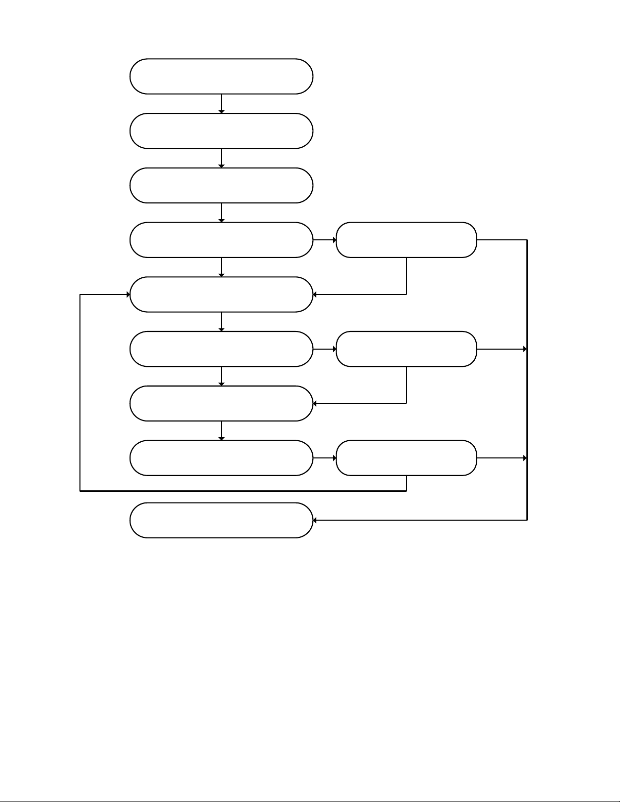
The standard chemical cleaning procedure is also summarized in Table 4 and Figure 1.

AQUADYN® FZ50 Series Hollow Fiber Module | OPERATION MANUAL
MICRODYN-NADIR | REVISION: B | DATE: 01/08/2020
13
TABLE 4. STANDARD CHEMICAL CLEANING PROCEDURE OF AQUADYN® FZ50 MODULES.
Step
Description
Chemical Solution
Concentration
Feed
Pressure
(MPa)
Time
(min)
Temperature (°C)
Circulation Flow Rate (m3/hr)
1
Measurement of flux (before chemical
cleaning)
-
-
-
-
-
2
Pure water 2-ports counter pressure
cleaning
-
0.1
2
Normal temperature
Max 14.5
3
Measurement of flux
-
0.05
-
-
-
4
Mixed chemical solution 2-ports
counter pressure cleaning
1 wt%
0.1
2
35
-
5
Mixed chemical solution soak
1 wt%
-
120
35
-
6
Mixed chemical solution 2-port counter
pressure cleaning
1 wt%
0.1
2
35
Max 14.5
7
Mixed chemical solution flushing
cleaning
1 wt%
-
20
35
15-20
8
Pure water 2-ports counter pressure
cleaning
-
0.1
2
Normal temperature
Max 14.5
9
Measurement of flux
-
0.05
-
-
-
10
NaClO 2-ports counter pressure
cleaning
50 ppm *
0.1
2
35
Max 14.5
11
NaClO soak
50 ppm *
-
720
35
-
12
NaClO 2-ports counter pressure
cleaning
50 ppm *
0.1
2
35
Max 14.5
13
NaClO flushing cleaning
50 ppm *
-
20
35
15-20
14
Pure water 2-ports counter pressure
cleaning
-
0.1
2
Normal temperature
Max 14.5
15
Measurement of flux
-
0.05
-
-
-
* NaClO concentration indicates the effective chlorine concentration.
AQUADYN® FZ50 Series Hollow Fiber Module | OPERATION MANUAL
MICRODYN-NADIR | REVISION: B | DATE: 01/08/2020
14
Operating data –this is where the
operating flux is determined
(1) Clean water flux before chemical
cleaning
Pure water counter pressure cleaning
(2) Measurement of flux
Cleaning with mixed chemical solution
(3) Measurement of flux
Cleaning with sodium hypochlorite
water solution
(4) Measurement of flux
(2) ≥ 90% of operating flux
(3) ≥ 90% of operating flux
(4) ≥ 90% of operating flux
End
Yes
Yes
Yes
No
No
No
Figure 1. By measuring the flux between each cleaning step, it is easy to determine if further or more intense
cleaning is necessary in order to restore membrane performance.

AQUADYN® FZ50 Series Hollow Fiber Module | OPERATION MANUAL
MICRODYN-NADIR | REVISION: B | DATE: 01/08/2020
15
7.2.1 Cleaning Steps
1. Discharge feed water from the module.
a. Fill the chemical solution tank with clean water.
b. Pump water to the feed water inlet port of the module and discharge it from the feed water outlet port and
the permeate port to discharge the feed water completely.
c. Then, discharge the pemreate fluid from the permeate port at the top of the module so that all air is
purged from the module. This prevents damage to the hollow fibers.
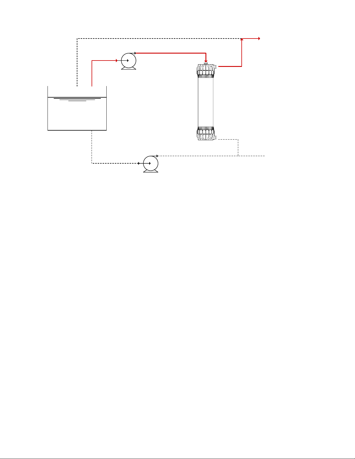
2. Water backwash
a. Feed the water into the permeate port (at the top of the module) at up to 0.1 Mpa for approximately one
minute (approximately 300 L or 80 gal) and discharge it from the inlet feed water port (see Figure 2). At
this time, close the permeate port at the bottom of the module and the outlet feed water port.
Chemical Solution Tank
Backwash Pump
Supply Pump
UF Module
Water Discharge
Water Discharge
Feed Water Outlet
Feed Water Inlet
Permeate Port
b. Next, feed the water from the permeate port at up to 0.1 Mpa and discharge it from the outlet feed port
and close the inlet feed port (see Figure 3). This should take about one minute (approximately 300 L or 80
gal).
Figure 2. Backwash flow where discharge water exists the feed water inlet port.
AQUADYN® FZ50 Series Hollow Fiber Module | OPERATION MANUAL
MICRODYN-NADIR | REVISION: B | DATE: 01/08/2020
16
Chemical Solution Tank
Backwash Pump
Supply Pump
UF Module
Water Discharge
Water Discharge
Feed Water Outlet
Feed Water Inlet
Permeate Port
3. Measurement of module performance
a. Measure the flux before cleaning.
b. For information on measuring module performance, please refer to
Section 7.2.2 Measuring the Flux.
4. Chemical Backwash
a. Prepare the chemical solution using the recommended concentrations. Make enough of the chemical
solution taking into account the volume of the module, piping, etc. Fill the chemical solution tank.
b. At this time, it is necessary to consider if additional chemcial solution is necessary to prevent the fluid level
in the tank to drop below the feed port.
c. Pressurize the chemical solution to the permeate port as done with backwashing. It is recommended to
discharge from the raw water side for about the same duration as backwashing, however, discharge at
least twice the module’s volume. This ensures the module is completely full of chemical solution.
d. Close the raw water inlet valve, feed outlet valve, and permeate port. Leave the module filled with the
chemical solution for a predefined time.
e. After the soak is complete, carry out the backwash using the chemical solution.
5. Flush cleaning using chemical solution
a. Prepare the chemical solution using the recommended concentrations. Make enough of the chemical
solution—about twice the volume needed to fill a module and the surrounding piping. Fill the chemical
solution tank.
b. Close the upper and lower permeate ports.
c. Begin the flush cycle. The chemical solution enters the inlet feed port and discharges it from the outlet
feed water port to the chemical solution tank for a predefined time.
d. At this time, the cleaning is more effective if a flow rate with higher linear speed is used within the hollow
fibers. A linear speed of about 0.5 to 1 m/sec (considering the pump capacity and pump consumption) is
recommended.
6. Water backwash
a. Perform a water backwash in the same way as Step 2 above. If the chemical solution isn’t washed out
entirely after the first water backwash, repeat the water backwash until all of the chemical solution is
washed out.
7. Flux measurement
a. Measure the flux of the module using the same procedure as outlined in Step 3 above.
8. Evaluation of celaning efficacy and replacement of chemical solution
a. Compare the operating data to the flux data obtained before and after the cleaning to evaluate cleaning
efficacy.
Figure 3. Backwash flow where discharge water exists the feed water outlet port.

AQUADYN® FZ50 Series Hollow Fiber Module | OPERATION MANUAL
MICRODYN-NADIR | REVISION: B | DATE: 01/08/2020
17
b. If the membrne performance is not sufficiently restored after one chemcial cleaning, repeat the cleaning
procedure (Steps 1-8).
7.2.2 Measuring the Flux
The clean water flux for AQUADYN®FZ50 modules is measured using ultrafiltered water at 0.05 MPa feed pressure, an
average transmembrane pressure (TMP) of 0.1 MPa and a temperature of 25°C (77°F).
The efficacy of the chemical cleaning is determined by comparing the clean water flux values before after chemical cleaning
(see Figure 4).
Flux Measurement Conditions
•Feed water: ulltrafiltered pure water
•Filtration mode: dead-end filtration by fully closing the feed water
outlet port
•Inlet pressure: approximately 0.05 MPa
Measurements
•P1: Module inlet pressure (refer to Figure 4)
•P2: Module outlet pressure
•P3: Module permeate pressure
•F1: Water quantity filtered by module (should be equivalent to
quantity of supplied water)
•T1: Water temperature
•t: Factor for correcting the temperature from T1 based on the
viscosity change of water (refer to Table 5)
Calculation of Flux
The flux converted per 25°C and 0.1 MPa is calculated with the following
formula:
Average TMP difference, P0 = {(P1+P2)/2} - {P3/2}
Flux, F = (F1*t) / (P0/0.1 MPa)
Figure 4. This diagram shows the three
different points on the module where
pressure is measured.

AQUADYN® FZ50 Series Hollow Fiber Module | OPERATION MANUAL
MICRODYN-NADIR | REVISION: B | DATE: 01/08/2020
18
TABLE 5. WATER TEMPERATURE CONVERSION TABLE (CONVERSION TO WATER TEMPERATURE 25°C).
Temperature (°C)
0
0.1
0.2
0.3
0.4
0.5
0.6
0.7
0.8
0.9
5
1.707
1.701
1.696
1.691
1.685
1.680
1.675
1.670
1.664
1.659
6
1.654
1.649
1.644
1.639
1.634
1.629
1.624
1.619
1.614
1.609
7
1.604
1.599
1.595
1.590
1.585
1.580
1.576
1.571
1.566
1.561
8
1.557
1.552
1.548
1.543
1.539
1.534
1.529
1.525
1.520
1.516
9
1.511
1.507
1.503
1.498
1.494
1.490
1.485
1.481
1.477
1.472
10
1.468
1.464
1.460
1.456
1.451
1.447
1.443
1.439
1.435
1.431
11
1.427
1.423
1.419
1.415
1.411
1.407
1.403
1.399
1.395
1.391
12
1.387
1.383
1.380
1.376
1.372
1.368
1.364
1.361
1.357
1.353
13
1.350
1.346
1.342
1.338
1.335
1.331
1.328
1.324
1.320
1.317
14
1.313
1.310
1.306
1.303
1.299
1.296
1.292
1.289
1.286
1.282
15
1.279
1.275
1.272
1.269
1.265
1.262
1.259
1.255
1.252
1.240
16
1.245
1.242
1.239
1.236
1.233
1.229
1.226
1.223
1.220
1.217
17
1.214
1.211
1.207
1.204
1.201
1.198
1.196
1.192
1.189
1.186
18
1.183
1.180
1.177
1.174
1.171
1.168
1.165
1.162
1.160
1.157
19
1.154
1.151
1.148
1.145
1.142
1.140
1.137
1.134
1.131
1.128
20
1.126
1.123
1.120
1.117
1.115
1.112
1.109
1.107
1.104
1.101
21
1.099
1.096
1.093
1.091
1.088
1.085
1.083
1.080
1.078
1.075
22
1.072
1.070
1.067
1.065
1.062
1.060
1.057
1.055
1.052
1.050
23
1.047
1.045
1.042
1.040
1.038
1.035
1.033
1.030
1.028
1.026
24
1.023
1.021
1.019
1.016
1.014
1.012
1.009
1.007
1.005
1.002
25
1.000
0.998
0.995
0.993
0.991
0.989
0.986
0.984
0.982
0.980
26
0.978
0.975
0.973
0.971
0.969
0.967
0.965
0.962
0.960
0.958
27
0.956
0.954
0.952
0.950
0.948
0.946
0.943
0.941
0.939
0.937
28
0.935
0.933
0.931
0.929
0.927
0.925
0.923
0.921
0.919
0.917
29
0.915
0.913
0.911
0.909
0.907
0.905
0.903
0.901
0.899
0.898
31
0.896
0.894
0.920
0.890
0.888
0.886
0.884
0.882
0.881
0.879
32
0.877
0.875
0.873
0.871
0.870
0.868
0.866
0.864
0.862
0.861
33
0.859
0.857
0.855
0.853
0.852
0.850
0.848
0.846
0.845
0.843
34
0.841
0.840
0.838
0.836
0.834
0.833
0.831
0.829
0.828
0.826
35
0.824
0.823
0.821
0.819
0.818
0.816
0.814
0.813
0.811
0.810
36
0.808
0.806
0.805
0.803
0.802
0.800
0.798
0.797
0.795
0.794
37
0.792
0.791
0.789
0.787
0.786
0.784
0.783
0.781
0.780
0.778
38
0.777
0.775
0.774
0.772
0.771
0.769
0.768
0.766
0.765
0.763
39
0.762
0.760
0.759
0.757
0.756
0.755
0.753
0.752
0.750
0.749
40
0.747
0.746
0.745
0.743
0.742
0.740
0.739
0.738
0.736
0.735
41
0.733
0.732
0.731
0.729
0.728
0.727
0.725
0.724
0.723
0.721
42
0.720
0.719
0.717
0.716
0.715
0.713
0.712
0.711
0.709
0.708
43
0.707
0.705
0.704
0.703
0.702
0.700
0.699
0.698
0.697
0.695
44
0.694
0.693
0.691
0.690
0.689
0.688
0.687
0.685
0.684
0.683
45
0.682
0.680
0.679
0.678
0.677
0.676
0.674
0.673
0.672
0.671
46
0.670
0.668
0.667
0.666
0.665
0.664
0.663
0.661
0.660
0.659
47
0.658
0.657
0.656
0.654
0.653
0.652
0.651
0.650
0.649
0.648
48
0.647
0.645
0.644
0.643
0.642
0.641
0.640
0.639
0.638
0.637
49
0.636
0.634
0.633
0.632
0.631
0.630
0.629
0.628
0.627
0.626
50
0.625
0.624
0.623
0.622
0.621
0.620
0.619
0.618
0.616
0.615
51
0.614
0.613
0.612
0.611
0.610
0.609
0.608
0.607
0.606
0.605
52
0.604
0.603
0.602
0.601
0.600
0.599
0.598
0.597
0.596
0.595
53
0.594
0.593
0.592
0.592
0.591
0.590
0.589
0.588
0.587
0.586
54
0.585
0.584
0.583
0.582
0.581
0.580
0.579
0.578
0.577
0.576
55
0.575
0.575
0.574
0.573
0.572
0.571
0.570
0.569
0.568
0.567
56
0.566
0.565
0.565
0.564
0.563
0.562
0.561
0.560
0.559
0.558
7.3
FREQUENCY OF CHEMICAL CLEANING
The frequency of chemical cleanings largely depends on the feed water quality, the operating flux and how much the feed
pressure has increased by. As a rule of thumb, it is recommended to clean at least every 6 months.

AQUADYN® FZ50 Series Hollow Fiber Module | OPERATION MANUAL
MICRODYN-NADIR | REVISION: B | DATE: 01/08/2020
19
8Return Shipment
If a module is to be returned to MICRODYN-NADIR, please fill the module with preservative solution.
If a sodium hypochlorite water solution is used, the effective chlorine may be consumed by the remaining contaminants.
After filling the module with the preservative solution, please check the free chlorine concentration.
If there’s a chance that the preservative may freeze during storage or transportation, please be sure to adopt a measure to
prevent freezing. If the module freezes, the membrane or casing may be damaged.
In order to prevent leakage or damage during transportation, carefully pack the module.
Please contact MICRODYN-NADIR if there are any questions about packaging or transportation of the module.

AQUADYN® FZ50 Series Hollow Fiber Module | OPERATION MANUAL
MICRODYN-NADIR | REVISION: B | DATE: 01/08/2020
20
9Disposal of the Module
Always follow proper disposal processes when discharging wastewater or preservative solution or when disposing a UF
module. If hazardous substances remain in the module, adopt a necessary measure to dispose of the module properly.
Table of contents
Other Microdyn Nadir Control Unit manuals

Popular Control Unit manuals by other brands

PVA
PVA FC100-CF Operation manual

Lutron Electronics
Lutron Electronics Grafik Eye GRX-4000 Series Installation, operation and maintenance manual

Bailey
Bailey Infi 90 IMDSM04 Instruction

UniPOS
UniPOS RS232 instruction manual

Danfoss
Danfoss PVG 100 Service manual

Siemens
Siemens SIRIUS ACT 3ZX1012-0SU14-1KA1 Original operating instructions


UTC Fire and Security
UTC Fire and Security interlogix VT4010 Installation & operation instructions

Rohl
Rohl Riobel PERRIN ROWE R46 instruction manual

Texas Instruments
Texas Instruments OPT3004EVM user guide

Lowell
Lowell MSM2 manual

Fortec Star
Fortec Star COMe-bSC6 manual

A.R.I.
A.R.I. Eliptix W-30 A Installation, Operating, Maintenance