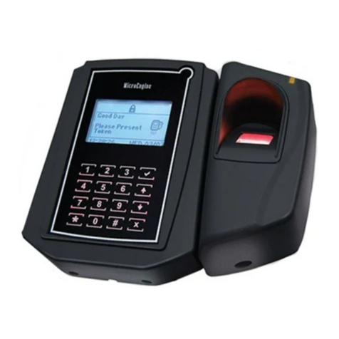
Microengine XP-GT Series Owner's manual

1
MicroEn
g
ine
®
XP-GT/GTR Programming Manual
v4.00
XP-GT/GTR
SINGLE DOOR ACCESS
CONTROL SYSTEM
PROGRAMMING MANUAL
Version 4.00

2
MicroEn
g
ine
®
XP-GT/GTR Programming Manual
v4.00
MicroEngine XP-GT/GTR Controller Programming Manual
Revision History
Version Date Remarks
1.00 1/1/2007 First Release of Manual
2.00 8/3/2008 Updated arrangements and drawings
2.10 17/7/2008 Updated drawings and included the XP-GTR series to the manual. Also
added a page to indicate scope of manual.
3.00 20/7/2009 Updated System Menu, added Alarm Menu and wiring diagram for XP-
GTR to MIO44. Also added the connection for XP-GT/GTR using
sounder and fire release feature.
4.00 3/10/2017 Updated drawings and included new XP-GT3500/GTR1500 series.

3
MicroEn
g
ine
®
XP-GT/GTR Programming Manual
v4.00
Scope:
This manual covers the following products
1. XP-GT1200
2. XP-GT3200
3. XP-GT1200L
4. XP-GT3200L
5. XP-GTR1200
6. XP-GTR3000
7. XP-GTR1200L
8. XP-GTR3000L
9. XP-GT3500L
10. XP-GT3500ABL
11. XP-GTR1500L
12. XP-GTR1500ABL

4
MicroEn
g
ine
®
XP-GT/GTR Programming Manual
v4.00
Table of Contents
A. XP-GT/GTR Single Door Access Control System......................................................6
i. Powering Up...................................................................................................................6
ii. Idle Mode ......................................................................................................................7
iii. Verification Mode...........................................................................................................7
a. Token Mode ...............................................................................................................7
b. Token+PIN Mode ........................................................................................................8
c. Token+Fingerprint Mode ..............................................................................................8
d. Token+Fingerprint+PIN Mode .......................................................................................8
iv. Symbols.......................................................................................................................................9
B. Programming Environment ......................................................................................10
i. Configuration Menu Layout.............................................................................................10
ii. Keypad Functions.........................................................................................................10
iii. Entering Configuration Mode .........................................................................................10
1. System Menu ...........................................................................................................13
1.1 Set Date and Time .....................................................................................................13
1.2 Door Parameter .........................................................................................................15
1.3 Time Set ...................................................................................................................20
1.4 Time Zone.................................................................................................................22
1.5 Holiday Setting...........................................................................................................25
1.6 General Parameter .....................................................................................................26
1.7 Network Parameters ...................................................................................................28
1.8 Sounder Setting .........................................................................................................30
1.9 O/P Trigger Events .....................................................................................................31
2. Database Menu ........................................................................................................33
2.1 Quick Add User..........................................................................................................33
2.2 Add User...................................................................................................................34
2.3 Delete User ...............................................................................................................36
2.4 Edit User Settings.......................................................................................................37
2.5 Clear Anti PassBack ...................................................................................................39
2.6 Clear Card LockOut ....................................................................................................39
2.7 Clear All User ............................................................................................................40

5
MicroEn
g
ine
®
XP-GT/GTR Programming Manual
v4.00
3. Fingerprint Menu ......................................................................................................41
3.1 Add Fingerprint ..........................................................................................................41
3.2 Delete Fingerprint.......................................................................................................43
3.3 Clear Fingerprint ........................................................................................................43
3.4 Template Enrolled ......................................................................................................44
3.5 Set Security Level ......................................................................................................44
4. Maintenance Menu...................................................................................................46
4.1 Change Master PIN ....................................................................................................46
4.2 Clear Transaction.......................................................................................................47
4.3 Test Watchdog...........................................................................................................47
4.4 Show Version ............................................................................................................48
4.5 Show Information .......................................................................................................48
5. Alarm Menu ..............................................................................................................49
5.1 Input Setting ..............................................................................................................49
5.2 Output Setting............................................................................................................51
5.3 Panel Status ..............................................................................................................53
6. Exit Programming Menu ...........................................................................................54
Appendix 1 – General Wiring for XP-GT using MAS-RBT......................................................55
Appendix 2 – General Wiring for XP-GTR using MAS-RBU ...................................................56
Appendix 3 – General Wiring for two XP-GT using MAS-RBT ................................................57
Appendix 4 - Connection for XP-GT using Sounder Feature ..................................................58
Appendix 5 - Connection for XP-GTR using Sounder Feature................................................59
Appendix 6 - Connection for XP-GT and XP-GTR using Fire Release Feature .........................60
Appendix 7 - Connection for XP-GTR to MIO44 ...................................................................61
Appendix 8 – General Wiring for XP-GT using MAS-RBM .....................................................62
Appendix 9 – General Wiring for XP-GTR using MAS-RBU ...................................................63
Appendix 10 – Wiring Connection for two XP-GT using MAS-RBM.........................................64
Appendix 11 – Wiring Connection for XP-GT using Sounder Feature......................................65
Appendix 12 – Wiring Connection for XP-GTR using Sounder Feature ...................................66
Appendix 13 – Wiring Modification for XP-GT to Fire Alarm Signal with Voltage Source ............67
Appendix 14 – Wiring Modification for XP-GTR to Fire Alarm Signal with Voltage Source ..........68

6
MicroEn
g
ine
®
XP-GT/GTR Programming Manual
v4.00
A. XP-GT/GTR Single Door Access Control System
i. Powering Up
Before powering up the controller for the first time, check that all the connections to the
hardware are connected properly according to the wiring diagram.
For first time controller start-up, perform a ColdStart operation to reset all controller
settings to default. For all new installation, ColdStart operation only needed to be
performed once unless specifically instructed to do so.
XP-GT/GTR (1200, 3000, 3200, 1200L, 3000L, 3200L) Series
To perform ColdStart, please follow the steps below:
1. Turn ON the power supply. The screen below will be shown:
MicroEngine
XP-GT3200L
v3.00
Starting up...
2. While the controller is starting up, press the #button.
3. Press
√to ColdStart the system, or Xto cancel.
4. Press
√again to confirm the ColdStart operation. Once the ColdStart process
finishes, the controller will automatically enter Idle Mode.
XP-GT/GTR (1500L, 3500L, 1500ABL, 3500ABL) Series
To perform ColdStart, please follow the steps below:
1. Ensure that the power supply is turned off.
2. Press and hold the ColdStart button at the back of the controller.
3. Turn ON the power supply. Release the ColdStart button after 2 seconds.
4. Controller will sound a long beep during the ColdStart operation and will
automatically enter Idle Mode once ColdStart process finishes.
.

7
MicroEn
g
ine
®
XP-GT/GTR Programming Manual
v4.00
ii. Idle Mode
In Idle Mode, the screen below will be shown:
Good Day
Please Present
Token
10:38:55 Tue,07/17
The controller will prompt different audio and visual indications to users under different
circumstances. Table below shows normal response in Idle Mode:
Condition LCD Display
Buzzer
Idle Mode 1. Request for a token to be presented.
OFF
2. Indicate time, date, and da
y
in “HH:MM:SS”
and “DAY,MM/DD”format.
3. Backli
g
ht is dimmed.
iii. Verification Modes
The controller can be operated in several verification modes for door access. To set the
verification modes for individual users, refer to Section 2.4 Edit User Setting under
Edit Verification Mode sub-menu.
The different verification modes are explained in the following sections:
a. ‘Token Only’ Mode
‘Token Only’ is the default verification mode of the controller. If the token type is
set as card, users have to present a card as identification. To read a card, place
the card near the keypad area. The time interval between successive readings of
the same card number is 2 seconds. If the token type is selected as pin, then
users have to present a 4-digit authorization pin as identification instead.

8
MicroEn
g
ine
®
XP-GT/GTR Programming Manual
v4.00
Table below shows controller’s responses in card operation mode:
Condition LCD Display Buzzer
Valid 1 bee
p
Token
Presented Valid Entry
ID: [801208]
10:38:55
Tue,07/17
Invalid 3 bee
p
s
Token
Presented Invalid Access
ID: [801208]
10:38:55
Tue,07/17
b. ‘Token+PIN’ Mode
Every card user will have its own four-digit pin number. In ‘Card+PIN’ mode, users
need to enter their respective pin numbers after flashing the access card. This
translates to a higher security level for the door access application.
NOTE:- All cards installed via the Database Menu will have a default pin
number of “1234”. To change the pin number, please refer to
Section 2.4 Edit User Setting.
c. ‘Token+Fingerprint’ Mode
Alternatively, users can opt to use the ‘Card+Fingerprint’ mode for higher levels of
access security. Each user can enrol up to 5 fingerprints for this purpose. For
enrolment of fingerprint, please refer to Section 3.1 Add Fingerprint.
d. ‘Token+PIN+Fingerprint’ Mode
For maximum security, the controller can be programmed to accept
‘Card+Pin+Fingerprint’ before granting door access.
Alternatively, the controller can also be programmed to accept ‘Fingerprint’ only or
‘Fingerprint+Pin’ verification mode according to the user’s requirements.
NOTE:- Fingerprint functions are only available to all XP-GT series.

9
MicroEn
g
ine
®
XP-GT/GTR Programming Manual
v4.00
iv. Symbols
Listed below are the common symbols that are used in the operation:
Symbol Name Description
Anti PassBack Enabled
Anti PassBack Mode enabled. Once enabled,
a user will not be able to use the same
card to gain access through the same
direction successively without first gaining
access from the opposite direction.
Card LockOut Enabled
Card LockOut Mode enabled. Once enabled,
the token will be locked permanently afte
r
failing to gain access three consecutive
times. The failure can be caused by wrong
pin number, wrong time zone or anti pass
back violations.
High Security Mode
High Security Mode enabled. Users need to
Enabled comply with the pre-set high security
mode requirements to gain access. This
provides higher levels of access security.
Security On
Security Mode enabled. Users must adhere
to the pre-set verification mode to gain
access.
Security Off
Security Mode Disabled. The door lock will be
permanently unlocked for free access.
Uplink communication Communication has been established
with the remote server when this icon is
blinking.
Downlink Communication has been established with
Communication the relay board when this icon appears.

10
MicroEn
g
ine
®
XP-GT/GTR Programming Manual
v4.00
B. Programming Environment
The MicroEngine XP-GT/GTR series controllers have an LCD display and a 4 x 4
keypad to allow users to program the functionalities of the controller. The programming
environment on the controller is called the configuration menu.
i. Configuration Menu Layout
The Configuration Menu layout is shown in page 12.
ii. Keypad Functions
1. To choose a menu or function, just enter the number corresponding to the
menu or function.
EXAMPLE:- In the main menu, pressing 1will enter System Menu.
2. Press 0-9 to key in card number, pin number or numeric value for certain
functions.
3. Press Xto cancel a function or return to the previous screen.
4. Press √to select a parameter to change/confirm a setting or value.
5. Press ↑or ↓to toggle between options or to scroll up/down the menu.
iii. Entering Configuration Menu
The controller can be programmed through two methods:
i. MicroEngine xPortal2005/xPortal2007/xPortal3000 software application.
ii. On-board keypad programming.
This manual will describe the steps to configure the controller using the built in keypad.
XP-GT/GTR (1200, 3000, 3200, 1200L, 3000L, 3200L) Series
To enter Configuration Menu, please follow the steps below:
1. Press '*' (asterisk).
2. Enter the 6 digits Master Pin (default Master Pin = “123456”). To change the
Master Pin, refer to Section 4.1 Change Master Pin.

11
MicroEn
g
ine
®
XP-GT/GTR Programming Manual
v4.00
XP-GT/GTR (1500L, 3500L, 1500ABL, 3500ABL) Series
To enter Configuration Menu for the first time, please follow the steps below:
1. Press '*' (asterisk).
2. Enter the 6-digits default Master PIN (“123456”).
3. Screen as below will be shown. Enter a new 6-digit Master Pin for enhanced
security levels.
4. Screen as below will be shown. Re-enter the same, new 6-digit Master Pin.
5. To enter Configuration Menu from here onwards, press the ‘*’ (asterisk) key
followed by the new 6-digit Master Pin entered earlier.
6. To change the Master Pin, please refer to Section 4.1 Change Master Pin.
Upon entering Configuration Menu, users will be able to see menu layout as shown in
page 12.
Chan
g
e MasterPIN
Enter New Master Pin
Pin: [------]
√- OK X - Cancel
Change MasterPIN
Re-Enter Master Pin
Pin: [------]
√- OK X - Cancel

12
MicroEn
g
ine
®
XP-GT/GTR Programming Manual
v4.00
6) General Para
5) Holiday Setting
4) Time Zone Setting
3) Time Set Setting
2) Door Parameter
Configuration Menu 1) System Menu 1) Set Date & Time
4) Edit User Setting
2) Delete Fingerprint
- Lock Release Time
- Door Open Time
- Lock Release TZ
- Exit Button TZ
- Autopin Mode
- Security Off
- Anti PassBack
- Card LockOut
- Tamper
- Hi Security Mode
- Hi Security TZ
- Int Reader Enable
- As Exit Reader
- Exit TZ Enable
- Sounder Period
- GP Output Mode
- GP Output Period
-GP Output TZ
- Fire Release
-Double Leaf
-Reader Type
- FP Auto Scan
1) Arm/Disarm Sensor
4) Sensor Arm TZ
5) View Sensor Status
4) Output TZ
3) Event Type
2) Output Type
1) Output On/Off
3) Trigger Delay
2) Arm Delay
3) Panel Status
2) Output Setting
1) Input Setting
5) Alarm Menu
5) Show Information
4) Show Version
3) Test Watchdog
2) Clear Transaction
1) Change MasterPin4) Maintenance
5) Set Security Level
4) Template Enrolled
3) Clear Fingerprint
1) Add Fingerprint3) Fingerprint Menu
7) Clear All User
6) Clear CardLockOut
5) Clear Antipassback
3) Delete User
2) Add User
1) Quick Add User
2) Database Menu
9) O/P Trigger Event
8) Sounder Setting
7) Network Setting
- System Address
- Advance Comm.
- Facility Code
- System Mode
- Enter Cfg by FP
- Enter Cfg by Cd
- Enter Cfg by ID
- Card Mode
- Swap Card
- Local IP Address
- Local Port No.
- Remote IP Address
- Remote Port No.
- Subnet Mask
- Gateway IP
Alarm Menu only
available to all
XP-GTR series.
Fingerprint Menu
only available to all
XP-GT series.

13
MicroEn
g
ine
®
XP-GT/GTR Programming Manual
v4.00
1. System Menu
1.1 Set Date and Time
System date and time is important to log event transactions, to activate Time Zone
controlled functions, and to activate holiday controlled functions.
XP-GT/GTR (1200, 3000, 3200, 1200L, 3000L, 3200L) Series
To program the date and time setting, please follow steps below:
1. Enter Configuration Menu.
2. Press 1for System Menu.
3. Press 1for Set Date & Time. Screen as below will be shown:
Set Date & Time
Y(2008) M[03] D[23]
h[13] m[23]
√- OK X - Cancel
8) Sounder Setting
6) General Parameter
5) Holiday Setting
3) Time Set Setting
4) Time Zone Setting
1) System Menu 1) Set Date & Time
- Lock Release Time
- Door Open Time
- Lock Release TZ
- Exit Button TZ
- Autopin Mode
- Security Off
- AntiPassBack
- CardLockOut
- Tamper
- Hi Security Mode
- Hi Security TZ
- Int Rdr Enable
- As Exit Reader
- Exit TZ Enable
- Sounder Period
- GP Output Mode
- GP Output Period
- GP Output TZ
- Fire Release
- Double Leaf
- Reader Type
-
FP Autoscan
- System Address
- Advance Comm.
- Facility Code
- System Mode
- Enter Cfg by FP
- Enter Cfg by Cd
- Enter Cfg by ID
- Card Mode
-SwapCard
- Local IP Address
- Local Port No.
- Remote IP Address
- Remote Port No.
- Subnet Mask
- Gateway IP
2) Door Parameter
7) Network Setting
9) O/P Trigger Events

14
MicroEn
g
ine
®
XP-GT/GTR Programming Manual
v4.00
4. The section with parenthesis, ( ), is the value selected for editing. Press X
if users wish to exit without saving changes.
5. Enter the ‘YEAR’ settings, press √to proceed to the next section.
6. Enter the ‘MONTH’ settings, press √to proceed to the next section.
7. Enter the ‘DATE’ settings, press √to proceed to the next section.
8. Enter the ‘HOUR’ settings, press √to proceed to the next section.
NOTE:- Specify time in 24-Hour format.
9. Enter the ‘MINUTE’ settings and press √to proceed to the next section.
Screen as below will be shown. Press √to save changes.
Set Date & Time
Save Changes?
√- OK X – Cancel
XP-GT/GTR (1500L, 3500L, 1500ABL, 3500ABL) Series
To program the date and time setting, please follow steps below:
1. Enter Configuration Menu.
2. Press 1for System Menu.
3. Press 1for Set Date & Time. Screen as below will be shown:
4. The underlined section is the value selected for editing. Press Xif users wish
to exit without saving changes.
5. Press
↑or ↓to select the ‘YEAR’, press √to proceed to the next section.
6. Press
↑or ↓to select the ‘MONTH’, press √to proceed to the next section.
7. Press
↑or ↓to select the ‘DATE’. Press √to proceed to the next section.
8. Press
↑or ↓to select the ‘HOUR’. Press √to proceed to the next section.
NOTE:- Specify time in 24-Hour format.
9. Press
↑or ↓to select the ‘MINUTE’ and press √to confirm. Screen as below
will be shown. Press √to save changes.
Set Date & Time
▸Y[2017] M[10] D[13]
H[16] M[14]
√
- OK X - Cancel

15
MicroEn
g
ine
®
XP-GT/GTR Programming Manual
v4.00
NOTE:- If controller has established communication with the software, the date
& time will automatically be synchronized with the PC’s date & time.
1.2 Door Parameter
This menu allows users to edit general door operation settings for the controller.
To program the door parameter setting, please follow steps below:
1. Enter Configuration Menu.
2. Press 1for System Menu.
3. Press 2for Door Parameter.
4. Press
↑or ↓to navigate the pointer to the desired parameter.
5. Press
√to edit the settings, followed by the desired setting values and √
again to save changes.
6. The screen below is shown, with the list of parameters available to program.
Door Parameter
▸Lock Release Time 10
Door Open Time 15
Lock Release TZ 00
Exit Button TZ 01
√
- OK X - Cancel
7. Press X if users wish to return to System Menu.
8. Screen as below will be shown. Press √to save changes.
Door Parameter
Save Changes?
√- OK X – Cancel
Set Date & Time
Save Changes?
√- OK X - Cancel

16
MicroEn
g
ine
®
XP-GT/GTR Programming Manual
v4.00
List of programmable parameters include:
i. Lock Release Time
Description : Duration for the lock to be released every time a valid
access is granted.
Value : 00 - 99 seconds.
Default value : 10 seconds.
ii. Door Open Time
Description : Duration for the door to be opened before being
considered as ‘Door Left Open’.
Value : 00 - 99 seconds.
Default value : 15 seconds.
iii. Lock Release Time Zone
Description : Time Zone setting for Automatic Lock Release. This
will determine the day of the week and the time of the
day to automatically release the door lock for free
access.
Value : 00 – 50.
Default value : 00. (No free access)
iv. Exit Button Time Zone
Description : Time Zone setting for Exit Button. This will determine
the day of the week and the time of the day where
the exit push button will be enabled.
Value : 00 – 50.
Default value : 01. (Exit button enabled at all times)
v. Auto Pin Mode
Description : AutoPin Mode enabled or disabled. Once enabled,
users can gain access only by entering a pre-
programmed pin number.
Value : ON, OFF.
Default value : OFF.
NOTE:- Sub-menu v. is only available to GT/GTR (1200, 3000, 3200, 1200L,
3000L, 3200L) series only.
vi. Security Off
Description : Security Off Mode enabled or disabled. Once enabled,
the door lock will be permanently released until this
parameter is disabled.
Value : NO, YES.
Default value : NO.

17
MicroEn
g
ine
®
XP-GT/GTR Programming Manual
v4.00
vii. Anti PassBack
Description : Anti PassBack Mode enabled or disabled. Once
enabled, users are prevented from using the same
card to gain access through the same direction
successively without first gaining access from the
opposite direction.
Value : ON, OFF.
Default value : OFF.
viii. Card Lock Out
Description : Card LockOut Mode enabled or disabled. Once
enabled, users will be locked out permanently after
failing to gain access for three consecutive times.
The failure might be caused by wrong pin number,
wrong time zone or anti passback violations.
Value : ON, OFF.
Default value : OFF.
ix. Tamper
Description : Tamper Mode enabled or disabled. Once enabled,
controller will sound buzzer when the cover is pried
open.
Value : ON, OFF.
Default value : OFF.
x. Hi Security Mode
Description : High Security mode selection. Users
can choose one of the 3 modes for additional
security. Hi Security Mode is activated by setting
the Hi Security Time Zone in the next menu.
Value : Token+Pin(00), Token+Fingerprint(01),
Token+Pin+Fingerprint(02).
Default value : 00
xi. Hi Security Time Zone
Description : Time Zone setting for Hi Security Mode. This will
determine the day of the week and the time of the day
where Hi Security Mode will be enabled.
Value : 00-50
Default value : 00 (Hi Security disabled)
xii. Int Rdr Enable
Description : Internal Reader enabled or disabled. Once enabled,
controller’s built-in reader will be enabled to read card
for door access application.
Value : YES, NO.
Default value : YES.
NOTE:- Sub-menu xii. is only available to GT/GTR (1500L, 3500L, 1500ABL,
3500ABL) series only.

18
MicroEn
g
ine
®
XP-GT/GTR Programming Manual
v4.00
xiii. As Exit Reader
Description : Built-in Reader enabled or disabled. Once enabled,
controller’s built-in reader is used as exit reader while
external reader is configured to be the entry reader.
Value : ON, OFF.
Default value : OFF.
xiv. Exit Time Zone Enable
Description : Exit Reader Time Zone Enable selection. Once
enabled, controller will enforce exit access according
to the pre-set user’s Time Zone. In the default setting,
the exit reader will always grant exit access even
though the user’s Time Zone is incorrect.
Value : ON, OFF.
Default value : OFF.
xv. Sounder Period
Description : Duration for the sounder to activate (in seconds)
when the sounder is triggered.
Value : 00-99.
Default value : 00.
NOTE:- Sub-menu xv. is only available to all GTR (1200, 3000, 1200L, 3000L,
1500L, 1500ABL) series only.
xvi. GP Output Mode
Description : GP Output Mode selection. Users can choose
one of three modes to trigger the output system.
[00]
–
Trigger by GP Output TZ (refer next menu)
[01]
–
Trigger by Sounder Setting (refer section 1.
8
)
[02]
–
Trigger by O/P Trigger Event(refer section 1.9
)
Value : 00-02.
Default value : 00.
xvii. GP Output Tz
Description : Time Zone setting for output activation. This will
determine the day of the week and the time of the
day where the output will be enabled.
Value : 00-50.
Default value : 00. (GP Output disabled)
xviii. GP Output Period
Description : Duration for the output to activate (in seconds)
when the output is triggered.
Value : 00-99.
Default value : 00.
NOTE:- Sub-menus xvi., xvii., and xviii. are only available to GT (1200, 3200,
1200L, 3200L) series only.

19
MicroEn
g
ine
®
XP-GT/GTR Programming Manual
v4.00
xix. Fire Release
Description : Fire Release Enable selection. Once enabled,
the controller will release the door lock when the fire
alarm signal is detected.
Value : NO, YES.
Default value : NO.
CAUTION:- Fire alarm signal must be a normally open dry contact (without
voltage source). To convert wet contact to dry contact, refer to
Appendix 13 and 14.
xx. Double Leaf
Description : Double Leaf Enable selection. Once enabled
both door leafs can be opened anytime within the lock
release time. If disabled, the both leafs must be
opened at the same time, otherwise one leaf will be
locked once the other leaf is opened.
Value : NO, YES.
Default value : NO.
xxi. Reader Type
Description : Reader Type selection. Users can choose one of four
reader types
[WG] – Wiegand reader
[AB] – ABA reader
[A10] – A10 reader
[RS] – RS485 reader (Plato)
Value : WG, AB, A10, RS.
Default value : AB.
NOTE:- Sub-menu xxi. is only available to GT/GTR (1500L, 3500L, 1500ABL,
3500ABL) series only.
xxii. FP Autoscan
Description : Fingerprint Autoscan enable selection. Once enabled,
the fingerprint reader unit will always be scanning for
valid fingerprint to grant door access.
Value : NO, YES.
Default value : NO.
NOTE:- Sub-menu xxii. is only available to GT (3500L, 3500ABL) series only.

20
MicroEn
g
ine
®
XP-GT/GTR Programming Manual
v4.00
1.3 Time Set
Time Set is the time interval that activates an operation or function. Time Set consists
of three time intervals that enable users to activate Time Zone controlled functions.
The GT/GTR (1200, 3000, 3200, 1200L, 3000L, 3200L) series controllers have 50
Time Sets while the GT/GTR (1500L, 3500L, 1500ABL, 3500ABL) series controllers
have an expanded 100 Time Sets.
Time Set 00 and Time Set 01 are default Time Sets which cannot be edited or deleted
by users. Time Sets that can be programmed by users are from 02 onwards.
The default setting for Time Set 00 and Time Set 01 are as follows:
Time Set 00 From To
Interval 1 00:00 00:00
Interval 2 00:00 00:00
Interval 3 00:00 00:00
Th
e diagram below shows the relationship between Time Set, Time Zone, and Time
Zone controlled functions:
Time Set Time Zone Functions
Time Set Time Zone Functions
attached assigned
Examples of Time Zone controlled functions are Auto Lock Release, Card+PIN, Exit
Button, AutoPIN, Hi-security Mode, Door Access, Input Arming, and Output Enable.
The Time Set can't be used directly to control the specified function. It has to be
attached in a Time Zone before assigning the Time Zone to the function. Detailed
description of Time Zone is available in Section 1.4 Time Zone.
EXAMPLE 1:-
During normal office hours, the lock of the company's main door will be released to
enable customers going in and out of the door. The door is locked at all times other
than the office hours.
Normal Office Hours : 08:30 to 17:30
Lunch Hour : 12:00 to 13:00
i.e. the lock will be released from 08:30 to 12:00 and from 13:00 to 17:30.
The sample Time Set is as below:
Time Set 02 From To
Interval 1
08:30 12:00
Interval 2
13:00 17:30
Interval 3
00:00 00:00
Time Set 01 From To
Interval 1 00:00 23:59
Interval 2 00:00 00:00
Interval 3 00:00 00:00
This manual suits for next models
13
Table of contents
Other Microengine Control System manuals
