MicroGuard 424 OPERATOR'S MANUAL Lattice/Horizontal Display
MG424 OPERATOR MANUAL Page 7 of 14 December 7, 2000
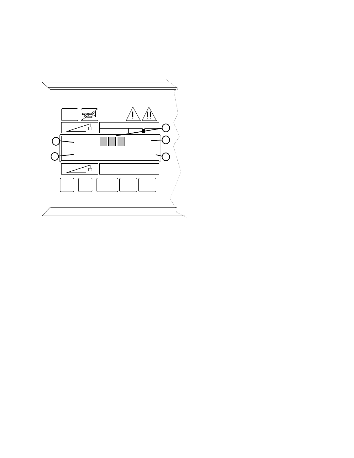
UPPER RIGHT DISPLAY
1 RADIUS/HEIGHT indicates
the area ofthe displaywhich gives
aread-out ofradius and height. It
is also amomentarypush-button
used to select the alternate display
ofheight. Height is displayed only
when the push-button is pressed
and held. When the push-button
is not pressed the displayis
always the radius ofthe load.
2 PARTS-OF-LINE indicates the
area ofthe displaywhich gives a
read-out ofthe parts ofline
currentlyselected. It is also a
push-button used to select the
parts ofline in use on the selected
winch.
3 WINCH SELECT indicates the area ofthe displaywhich gives aread-out ofthe winch currently
selected. It is also the push-button which is used to select the Main or Auxiliarywinch. When switching
between winches the parts ofline previouslyselected for the other winch is remembered and displayed
whenever the alternate winch is selected.
4 ANGLE/LENGTH indicates the area ofthe displaywhich gives aread-out ofangle or length. It is also
amomentarypush-button used to select the alternate displayofLength. Length is displayed onlywhen
the push-button is pressed and held. When the push-button is not pressed the displayis alwaysthe Angle
ofthe main boom.
5 WORKING AREA indicates the part ofthe displaywhich showsthe working area. Messages in this
area will conformto the current dutyselection and the swing position ofthe crane upper for
machines which have swing and multiple working swing areas.
6 TARE is apush-button, which is used to “tare”out the weight ofhookand slings. The actual load
displaywill then displaythe actual weight ofthe load being lifted. The bargraph displaywill continue to
reflect the percentage ofthe total weight belowthe boomhead.
Toset the tare: With the hookand slings lifted, press and hold the TARE button for three seconds.
The displayconsole will beep after three seconds and will “zero”the actual load display.The TARE
lamp (#3 on next page) will then illuminate to indicate that a tare has been set.
Toclear the tare: Press the TARE button momentarily.The displayconsole will immediatelybeep,
the actual load displaywill showthe total weight belowthe boomhead and the TARE lamp (#3 on next
page) will be off.
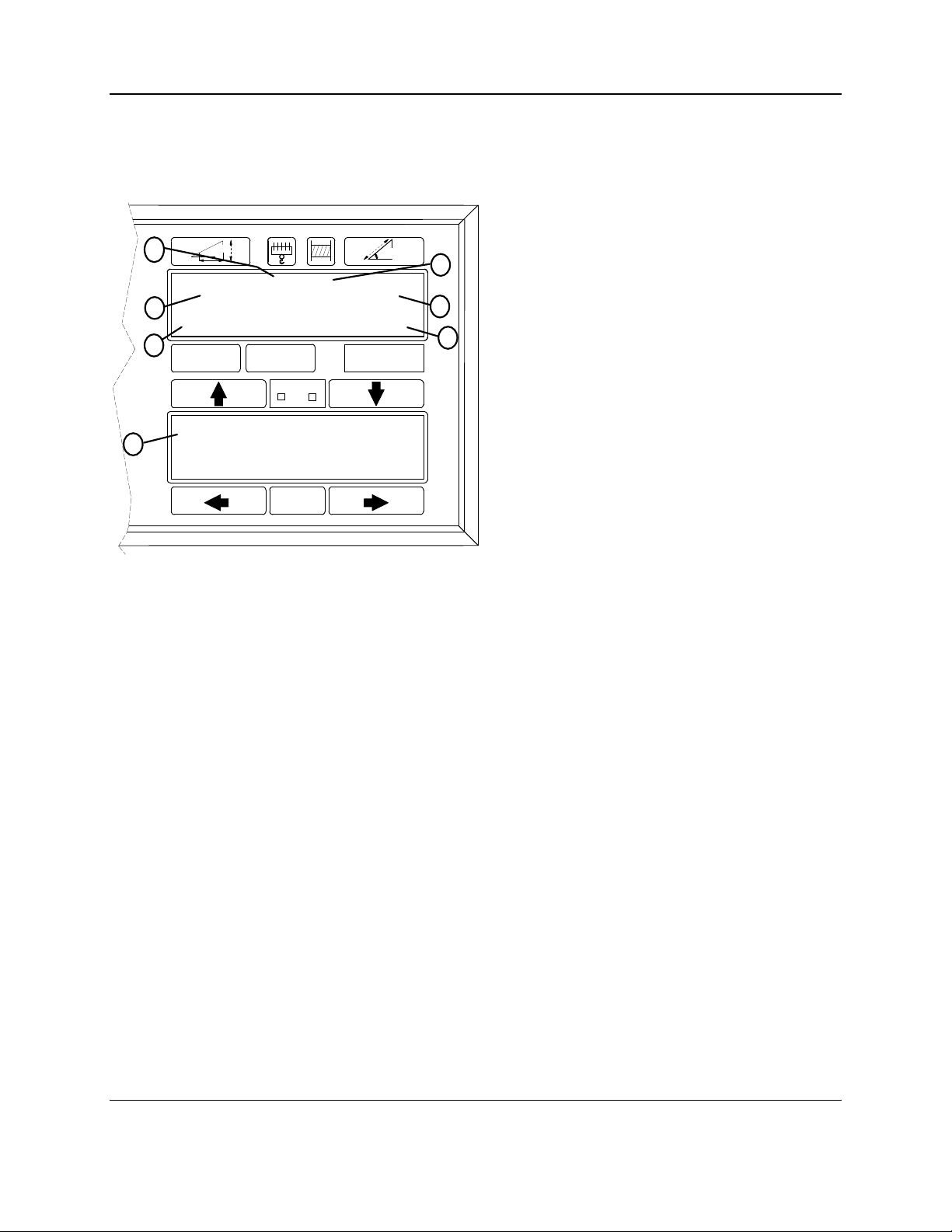
7 CRANE SETUP indicates the area ofthe displaywhich gives aread-out ofthe selected on or off rail
configuration. It is also apush-button used to start the selection ofthe machine configuration.
CRANE
SET UP WORKING
AREA
TARE
1
2 3 4
5
6
7
UPPER RIGHT DISPLAY