MR430 Fiber Optic Position Sensor System
Page 3 of 50
Table of Contents
1. Product Description ............................................................................................. 5
1.1 Position Sensor Background .........................................................................................5
1.2 Fiber Optic Position Sensor ..........................................................................................5
1.3 Features.........................................................................................................................6
2. Initial Preparation .................................................................................................7
2.1 Unpacking and Inspection ............................................................................................7
2.2 Damage in Shipment ....................................................................................................7
2.3 Standard Contents ........................................................................................................7
3. Installation and Operation.................................................................................... 8
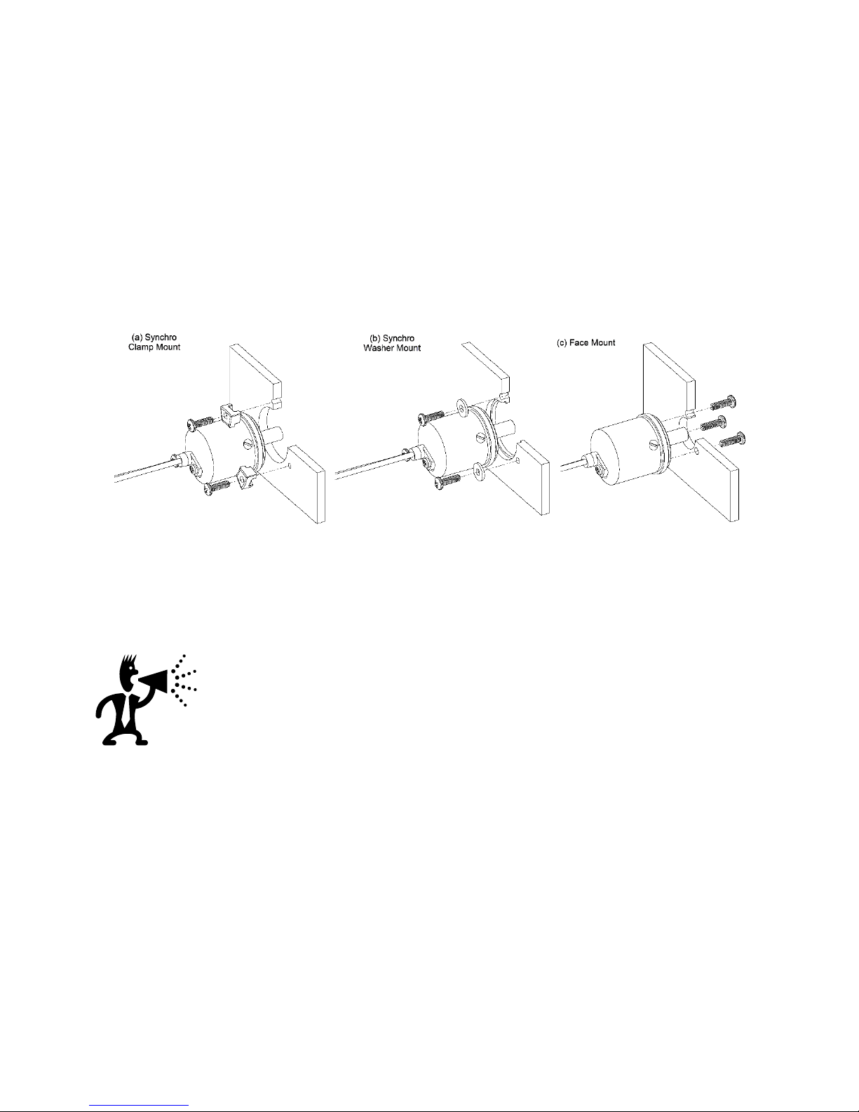
3.1 Mounting the Sensor Unit .............................................................................................8
3.2 Mounting the Controller Unit........................................................................................9
3.3 USB (J2) and RS485/SSI Interface Connections (J3) ...................................................11
3.4 Optical Connection .....................................................................................................12
3.5 Blink Status and Error Codes ......................................................................................12
3.6 System Start-Up Without PC Computer .....................................................................13
3.7 Functional System Overview.......................................................................................14
3.8 Turn-Counter and Turn-Counter Size..........................................................................16
3.9 Multi-Turn Operation ..................................................................................................17
3.10 Battery Backup for Multi-Turn Operation ...................................................................17
3.11 SSI Interface ................................................................................................................18
3.12 Voltage Output ...........................................................................................................20
3.13 Isolated Current Output (4-20mA) ..............................................................................22
3.14 Digital Set Point ..........................................................................................................23
4. Serial Communication – Modbus ....................................................................... 25
4.1 USB-Serial Emulator ....................................................................................................25
4.2 Serial Interface Specification.......................................................................................26
4.3 Physical Connection for Modbus operation ...............................................................26
4.4 Serial Bus Termination Resistor...................................................................................27
4.5 MODBUS Communications Protocol ..........................................................................27
5. MR430 - Error Handling and Troubleshooting.................................................... 33
5.1 Explanation of Status and Error Handling...................................................................33
5.2 Explanation of Status and Error Indication .................................................................33
5.3 Reading the Error Counters ........................................................................................38
5.4 About Statistical Read Error Determination................................................................38
5.5 Warranty Information ..................................................................................................40
6. Specifications ..................................................................................................... 41
6.1 MR430 Controller Specification ..................................................................................41
6.2 MR431 Sensor Specifications ......................................................................................42