manuals.online logo
Brands
  1. Home
  2. •
  3. Brands
  4. •
  5. Micronor
  6. •
  7. Media Converter
  8. •
  9. Micronor ESAV Series User manual

Micronor ESAV Series User manual

Absolute encoders – ESAV/ENAV series
www.micronor.com Specifications subject to change without notice, 98-0ENC-04-A, released 11/29/2023
Standard electronic, magnetic
multiturn, singleturn, analog
Instruction Manual
Page 1 of 4
Table of Contents
1. Recommended wiring
2. Function and Status LED
3. Default Settings
4. Programming
4.1 Scaling function (multiturn only)
4,2 Zero set function (singleturn only)
4.3 Direction of rotation change (multiturn only)
4.4 Limit switch function (multiturn only)
1. Recommend Wiring
The interface has simply 3 signal wires for signal transmission.
•Use exclusively shielded twisted-pair cable to connect the device.
•Comply with the maximum permissible connection cables length.
•Preferably connect the shield on both sides with low impedance to the protective earth (PE), e.g.on the device and/or on the evaluation unit. In the event of
potential differences, the shield must only be applied on one side.
Sensor Voltage source
Recommended input wiring
2. Function and Status LED
The device is equipped with a two-color LED for display status and error messages:
•Green = status
•Red = error
Display LED Meaning Error cause Note
No LED on
Encoder not in operation
Faulty supply voltage
Encoder not operational
Check the voltage supply and
the wiring.
Green LED flashes in
250ms cycles
Service mode
The encoder is in
Service mode.
Contact the Micronor Sensors
support.
Green LED
c
onstantly on
Encoder
in operation
Red and green LEDs
flash
alternately in
250ms cycles
System error
Internal system error
Contact the Micronor Sensors
support.
Red and green LEDs
flash alternately in
500ms cycles
Wire break
(only for current output)
Load at the output too
low. Connection with the
control interrupted.
Check the wiring
Green and red LED
constantly
on
Reference
point display
Green LED
flashes 1x
Activation of SET 1 input
detected and
confirmed.
Green LED
flashes 3x
Activation of SET 2 input detected.
The new measuring range has taken
over.
Red LED
flashes
3x
Error
during the scaling
operation.
The new measuring range has
not taken over.
Selected
measuring
range
:
< 22.5°
or
>
65536 revolutions
Scale another measuring
range
Green / red / green
sequence
Reset of the scaled measuring
range.
Default measuring range
is
loaded. Preset is carried
out at
the current posi
tion.
Zero
set function confirmed with
singleturn devices.
Absolute encoders – ESAV/ENAV series
www.micronor.com Specifications subject to change without notice, 98-0ENC-04-A, released 11/29/2023
Standard electronic, magnetic
multiturn, singleturn, analog
Instruction Manual
Page 2 of 4
3. Default Settings
As a standard, the output signal (4 … 20 mA, 0 … 10 V, 0 … 5 V) is output scaled over the set measuring range.
Depending on the configuration, the measuring range can be as follows:
•For singleturn devices: 1 revolution
•For multiturn devices: 16 revolutions (factory setting)
If supported by the device, the measuring range can also be freely scaled.
Also the direction of rotation depends on the configuration of the used device. It affects the signal path.
The possible configurations are shown below.
1
Variant 4 … 20 mA
3
Variant 0 … 5 V
2
Variant 0 … 10 V
4
Rollover
Singleturn devices
The measuring range of the singleturn devices varies according to the version. The pictures below can be used to represent the behavior of the measuring range.
Absolute encoders – ESAV/ENAV series
www.micronor.com Specifications subject to change without notice, 98-0ENC-04-A, released 11/29/2023
Standard electronic, magnetic
multiturn, singleturn, analog
Instruction Manual
Page 3 of 4
4. Programming
4.1 Scaling function (multiturn only)
Multiturn devices
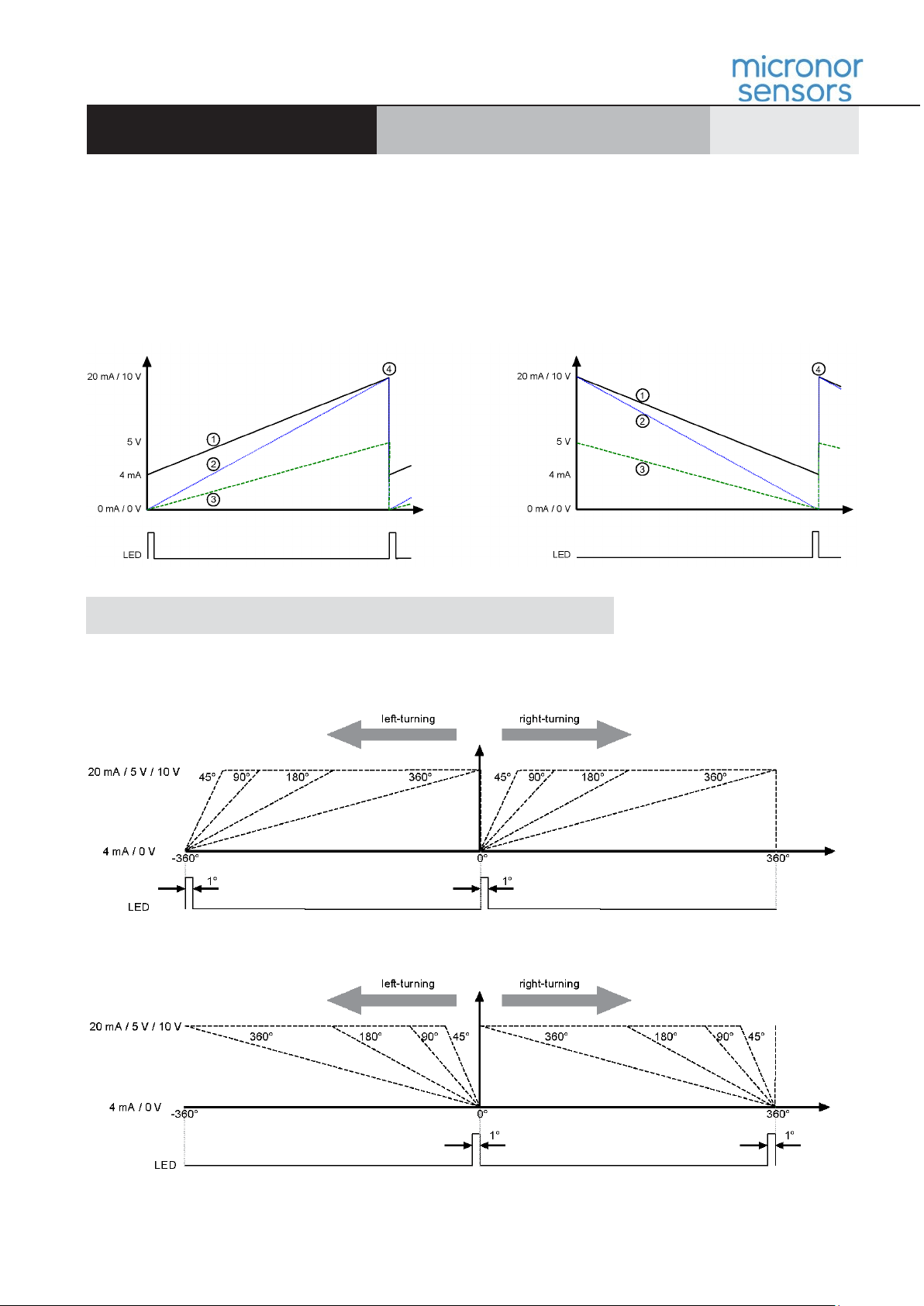
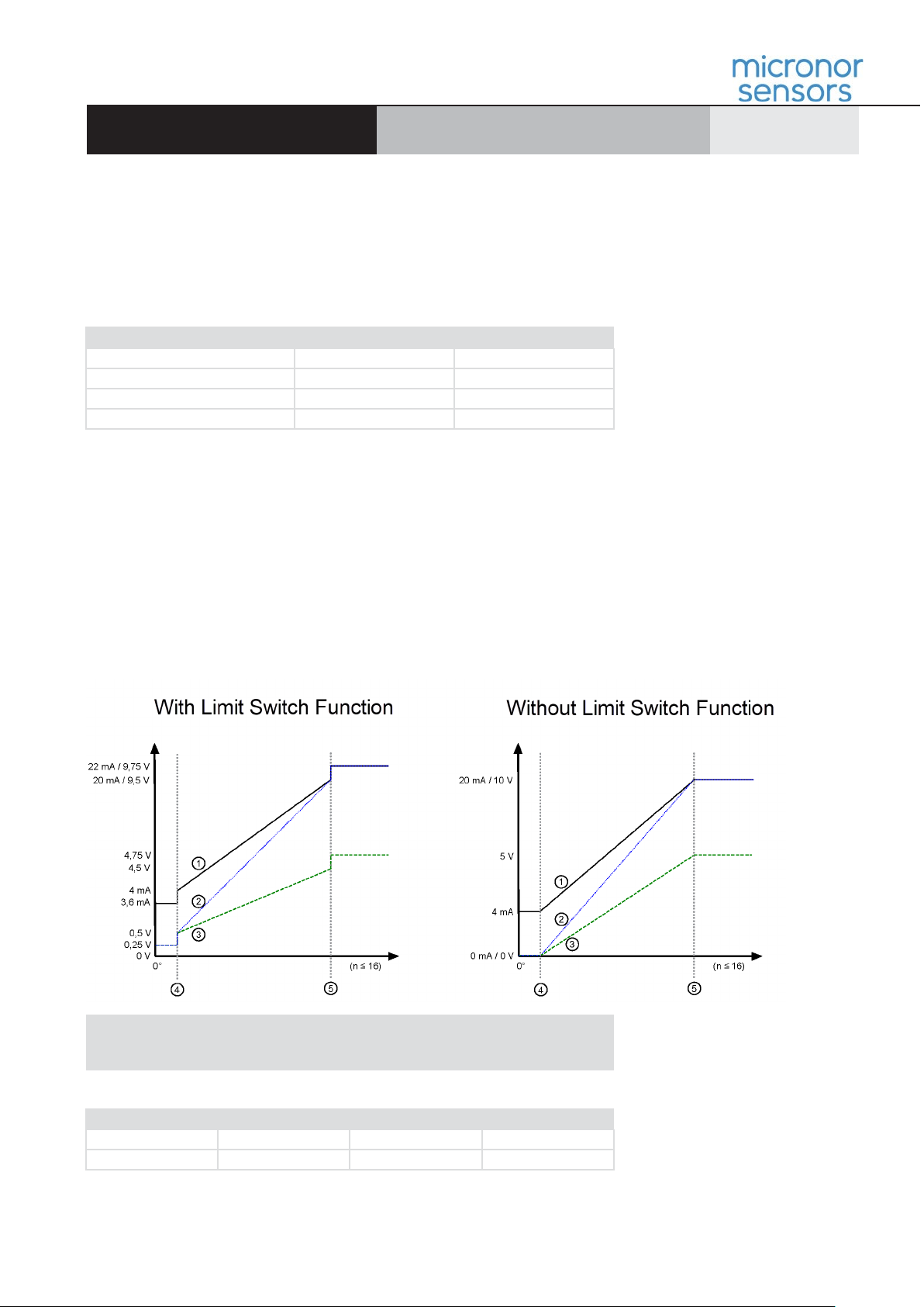
The encoder is factory-set for a measuring range of 16 revolutions. Linear scaling is applied to the respective output signal.
The encoder is factory-set for a determined output range of 4 … 20 mA / 0 … 10 V / 0 … 5 V. It is scaled linearly over the desired measuring range.
The two scaling inputs SET 1 and SET 2 allow the user to set a measuring range himself. The desired measuring range must be > 22.5° and shall not exceed
65536 revolutions. To restore the default measuring range, apply + V to both SET inputs.
Important Notice:
•To trigger the scaling operation, apply the supply voltage + V to the corresponding scaling input at least 1 second.
•The scaling function is limited to 10,000 cycles. Beyond this limit, the error-free scaling of the output signal cannot be guaranteed.
•Actuate the SET inputs only once the shaft has stopped. Only this way will it be possible to take over properly the desired start and end position of the desired
signal scaling.
•If the inputs are not used, they should be connected to 0V (encoder ground GND), to prevent interferences.
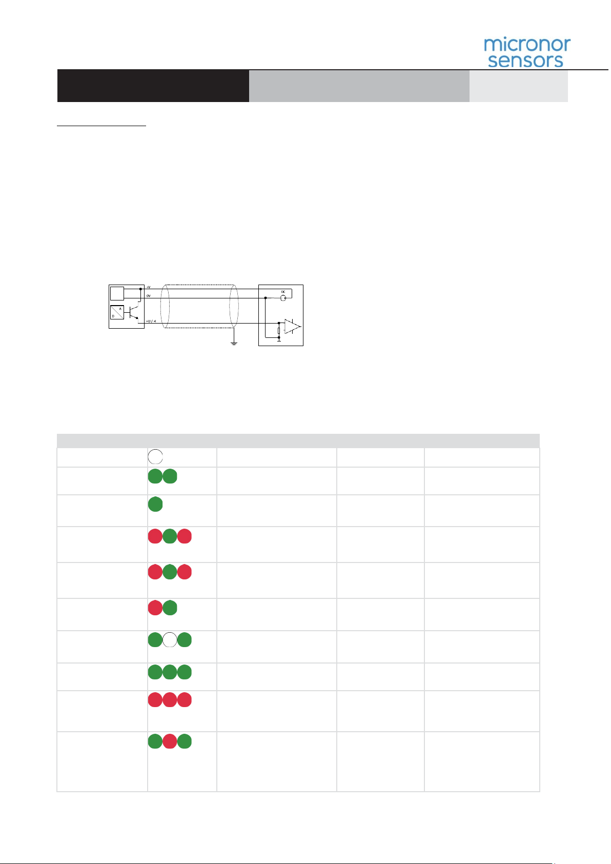
Scaling process for multiturn devices:
1) Turn the shaft to the desired start position.
2) Apply +V to input SET 1 for at least one second.
►The green LED flashes 1x
3) Turn the shaft to the desired end position.
4) Apply +V to input SET 2 for at least one second.
►The green LED flashes 3x. The new measuring range is active. The output signal jumps to the maximum value.
Resetting the scaled output signal for multiturn devices:
1) Make sure that the shaft stands still.
2) Apply +V to input SET 1 for at least one second.
►The green LED flashes 1x
3) Turn the shaft to the desired end position.
4) Apply +V to input SET 2 for at least one second.
►The green LED flashes 3x. The new measuring range is active. The output signal jumps to the maximum value.
If the inputs are not used, they must be connected to 0 V (encoder ground GND), to prevent in- terferences.
SET 1
input SET 2 input Function
0
0
Normal operating mode
1
0
Setting the start position
0
1
Setting the end position
1
1
Resetting to the default measuring range
0
0
Normal operating mode
Singleturn devices
For singleturn devices, the measuring range cannot be scaled. It is factory-preset and displayed by the reference point display. However, the measuring range can be
shifted by the Zero set function.
Reference point display for singleturn devices:
With the factory-set "default" scaling, the LED displays the reference point of 0 ... 1°. The reference point display is no longer available if another measuring range is
scaled using the scaling inputs.
4.2 Zero Set Function (singleturn only)
With singleturn devices, the Zero set function allows shifting the measuring range. For this purpose, the current position is set to 0. The size of the measuring range
remains unchanged.
If this input is not used, it must be connected to 0V (encoder ground GND), to prevent interferences.
Zero set with singleturn devices:
1) Turn the shaft to the desired start position.
2) Apply +V to input SET 1 for at least one second.
►The green LED flashes 3x – green/red/green. The new measuring range is active
Absolute encoders – ESAV/ENAV series
www.micronor.com Specifications subject to change without notice, 98-0ENC-04-A, released 11/29/2023
Standard electronic, magnetic
multiturn, singleturn, analog
Instruction Manual
Page 4 of 4
4.3 Direction of rotation change (multiturn only)
Multiturn devices
Fixed output levels are assigned to the scaling inputs.
•SET 1 = lowest output level (current variant = 4 mA / voltage variant = 0 V)
•SET 2 = highest output level (current variant = 20 mA / voltage variant = 5 or 10 V)
This means that the actuation order determines the logic of the direction of rotation. If input SET 2 is actuated first, followed by input Set 1, the new measuring range is
defined with the reversed direction of rotation.
Order of the SET inputs
Absolute position
Sign
1 - 2
1 > 2 CCW
Positive
1 - 2
2 > 1 CW
Positive
2
- 1
1 > 2
CW Negative
2 - 1
2 > 1 CCW
Negative
4.4 Limit switch function (multiturn only)
Multiturn devices
With the limit switch function, the output signal does not remain at the last final value, but it makes a defined jump. This signal jump can be used by a control as a limit
switch. The output levels of the limit switches are factory-set. The output levels are represented below for a better illustration, once with and once without the limit switch
function. The picture represents the factory-set total measuring range of 16 bits (NDR = 4 bits = 16 revolutions).
Measuring ranges with/without limit switch function
Fixed output levels are assigned to the
With singleturn devices, the Zero set function allows shifting the measuring range. For this purpose, the current position is set to 0. The size of the measuring range
remains unchanged.
If this input is not used, it must be connected to 0V (encoder ground GND), to prevent interferences.
1
Variant 4 … 20 mA
4
Teach point 1
2
Variant 0 … 10 V
5
Teach point 2
3
Variant 0 … 5 V
Measuring range in delivery (default) condition: NDR = 4 bits = 16 revolutions
Variant
4 … 20 mA 0 … 10 V0 … 5 V
Limit switch low
3.6 mA
0.25 V
0.25 V
Limit switch high
22.0 mA
9.75 V
4.75 V

This manual suits for next models

2

Other Micronor Media Converter manuals

Micronor MR330 Series User manual

Micronor

Micronor MR330 Series User manual

Micronor MR320 Series User manual

Micronor

Micronor MR320 Series User manual

Micronor MR310 Series User manual

Micronor

Micronor MR310 Series User manual

Micronor MR430 Series User manual

Micronor

Micronor MR430 Series User manual

Popular Media Converter manuals by other brands

Matrox Mojito MAX Installation and user guide

Matrox

Matrox Mojito MAX Installation and user guide

ADF Web HD67672-IP-2-A1 user manual

ADF Web

ADF Web HD67672-IP-2-A1 user manual

Renishaw QUANTiC RTLC40-S installation guide

Renishaw

Renishaw QUANTiC RTLC40-S installation guide

ST STEVAL-ISV002V2 user manual

ST

ST STEVAL-ISV002V2 user manual

STEINWAY LYNGDORF C installation manual

STEINWAY LYNGDORF

STEINWAY LYNGDORF C installation manual

NTI 3GSDI-USB3-CPTR-HDO Installation and operation manual

NTI

NTI 3GSDI-USB3-CPTR-HDO Installation and operation manual

Cobalt Digital Inc HD-8019 owner's manual

Cobalt Digital Inc

Cobalt Digital Inc HD-8019 owner's manual

TELES CellX Box series System manual

TELES

TELES CellX Box series System manual

Transition Networks E-100BTX-FRL-03(SC) E-100BTX-FRL-03(SM) user guide

Transition Networks

Transition Networks E-100BTX-FRL-03(SC) E-100BTX-FRL-03(SM) user guide

KTI Networks KC-10FM installation guide

KTI Networks

KTI Networks KC-10FM installation guide

Transition Networks HSTR-CF-01(SC) user guide

Transition Networks

Transition Networks HSTR-CF-01(SC) user guide

Z3 Technology Z3-MVPR-02 user guide

Z3 Technology

Z3 Technology Z3-MVPR-02 user guide

infobit iTrans DP-T-22 user manual

infobit

infobit iTrans DP-T-22 user manual

LLURIA DMR-KNX-DIN4 quick start guide

LLURIA

LLURIA DMR-KNX-DIN4 quick start guide

Sensata Newall Spherosyn & Microsyn 300 Quick install guide

Sensata

Sensata Newall Spherosyn & Microsyn 300 Quick install guide

Ace Plus EX-G065 user manual

Ace Plus

Ace Plus EX-G065 user manual

Viessmann Basic 5237 manual

Viessmann

Viessmann Basic 5237 manual

Woxcon CE-DA14-H2 user manual

Woxcon

Woxcon CE-DA14-H2 user manual

manuals.online logo
manuals.online logoBrands
  • About & Mission
  • Contact us
  • Privacy Policy
  • Terms and Conditions

Copyright 2025 Manuals.Online. All Rights Reserved.