MicroPace EPS320B User manual

EPS320B
CARDIAC STIMULATOR
QUICK INSTALLATION GUIDE
Micropace Document Part No. MP3156
Ver 1.8
Rx only
User Configuration Menu password: ‘henry’ or 4546
Service Configuration Menu password: ‘service’ or 9897
Check for latest Version of EPS320B Installation Manual at http://www.micropaceep.com/ - Downloads
page
Applies to:
EPS320 Software V3.21 SR1, SR2+, V4.0
Two and Four Channel Stimulus Multiplexer Box
Touch Screen

EPS320B Cardiac Stimulator
2
Quick Installation Guide for 4 channel Touch Screen Stimulator
Unpack and verify all components are present as per Packing List.
a. MP3113B-X (Touch screen)
b. MP3102BT-X-X (SGU/Bona PC Carton and cable accessories)
Figure 1 MET Laboratories Inc. approved components shown on the left.
1
Stimulus
Generator
Unit (SGU)
MP3008
SGU Power
Supply
MP3074
Stimulus
Multiplexor
BOX MP3086
Patient Box
MP30141
Serial
Boost
MP3033A
Stimulus
Extension
MP3070
Installation Kit
MP3063
BNC to
Phono
MP3109
Signal
cable
MP3034
Universal
Transformer
MP3107
Keyboard
MP3016
SM-Box Extension
cable MP3090
Accessories
Box
MP3055
Bona PC
MP3093
MET Laboratories Inc.- Certified E212294
Note 1 : Optional part, not a component of MP320BFULL.
Touch screen
MP3113-GE
(Part of
MPEPS320FULL-A)

GE-EPS320B Combo Quick Install Guide
3
NRTL Listed equipment approved by MET Registration Number E212294
Item
Part No
Description
1
MP3008
Stimulus Generator Unit ( SGU )
2
MP3074
Power Supply GTM21089-1815-T2 ( PSU1 )
3
MP3109
BNC to Phone Signal Cable
4
MP3033A
Serial Boost RS232 Cable ( 2m )
5
MP3034
Signal cable with Phone Plugs
6
MP3063
Installation Kit Incl. (i) 4X Fuses T1.25A 250V, (ii) LED Tester MP3058
7
MP3086
Stimulus Multiplexer BOX
8
MP3070
Stimulus Extension cable
Optional approved parts
9
MP3014
Stimulus Connection Box
10
MP3084
RS232 Extension Cable 25 Meters
Table 1 NRTL approved equipment
You will be Interconnect the five main components according to the below overview and
subsequent detailed instruction steps 2 –4. Ensure all components have adequate ventilation.
Figure 2 Overview of Stimulator Connections
3
2

EPS320B Cardiac Stimulator
4
Lay out and connect Stimulus cabling, (under ground if required) between EPS320 Stimulus
Generator Unit (SGU) and EP Amplifier (LS Pro and CardioLab recorders shown):
Warning: To prevent patient micro-electrocution through capacitively coupled leakage currents,
MP3070 and MP3126 cable installation must be (i) appropriately insulated and separated from any nearby
mains wiring to prevent injection of mains voltage through broken insulation, (ii) must not be installed next
to mains voltage–energised cables and (iii) should not be installed within grounded conduits. Installation
should be acceptance tested by biomedical engineer for Patient Applied Part, Class CF device.
Note that when longer (>15m) length of Extension Stim Cable is required, it is preferable to place the
SGU in the operating room on top of the Amplifier under the patient table and use a long 80’/25m
serial cable MP3084-25 to interconnect PC with SGU. This will reduce noise and ground leakage
currents in the whole installation.
Note: for CardioLab II, ECG
output is found on the IEB
Labelled “Anlg Out - 1”.
1
CardioLab IEB
CardioLab Amplifier
LS Pro Amplifier
LS Pro Amplifier

GE-EPS320B Combo Quick Install Guide
5
Connect all power supplies to Isolation transformer and interconnect SGU and PC serial ports
with MP3033A.
4

EPS320B Cardiac Stimulator
6
Interconnect Eps320b Computer, LCD Display And SGU:
5

GE-EPS320B Combo Quick Install Guide
7
Now Set up the computer:
a. Switch on (i) Isolation transformer, (ii) Bona PC (push front button once), (iii) LCD
Display (on the side) and (iv) SGU at the rear. Allow system to boot up.
b. When prompted respond that you are the distributor (to avoid having the License
agreement shown to you)
c. If you have an EU version, you will be offered a menu to chose an interface language.
d. When prompted to calibrate screen, touch screen in the places indicated by crosses
from the seated position and the same eye level as the customer will use, using the
stylus.
e. You will now see the Mains Stimulator Screen as below:
f. The stimulator software will already be configured for the hardware setup you
purchased –touch screen, four channels and one external ECG.
6
7

EPS320B Cardiac Stimulator
8
Verify System (use checklist on last page):
a. Verify Isolated Mains. Visually verify that all EPS320B components –PC, SGU, LCD
Screen, are connected to a Medical Grade Mains Isolation Transformer e.g. MP3107.
b. Clean launch. Verify that SGU and Software launch without errors.
c. Test Pacing channels. Insert Stimulus Test LED, MP3058 (from the Installation Kit in
the Accessories Box) ) into the EP Recording Equipment’s bedside catheter input
modules (CIM’s) - Block A. Configure the EP Recording Equipment to stimulate those
outputs from the Chan 1 Atrial stimulation channel. Set current to 25mA and
commence pacing into the Atrium.
The Stimulus Test LED should light with pacing (Yellow light indicates that the
stimulus pulse is positive at the red connector and negative at the black one while
Red light indicates the opposite or wrong polarity).
Repeat pacing test for all four channels, using other 3 CIM Blocks. Similarly verify that
Emergency Fixed Rate Pacing (red output socket) stimulates into Ventricle / Chan 2.
d. Verify ECG sensing. Connect ECG simulator to EP recorder surface leads, select
one channel to sense from and verify that EPS320B Stimulator displays the ECG on
the screen (if you don’t have a simulator, create some noise on channel by touching
the electrode).
e. Safety Acceptance. Finally, organise Biomedical engineering to perform acceptance
test the entire installed system according to the health facilities’ procedure’s.
f. Troubleshooting. If there are problems, refer to the troubleshooting section below, in
the Installation Manual, the User Instruction Manual or the Micropace Connect iPad
Application.
g. Make a record. Make a record of the verified installation and sign and date according
to your company’s quality system and file as required.

GE-EPS320B Combo Quick Install Guide
9
Train Customer
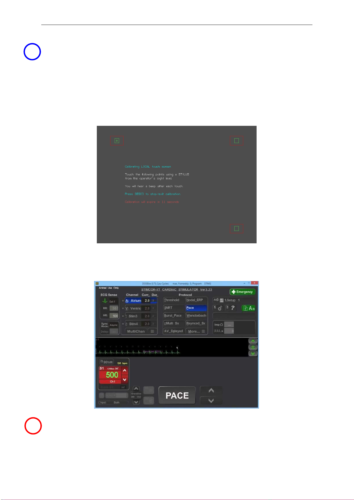
a. Customize Stimulator settings. Sit down with the responsible customer –chief
technician or physician and set up various defaults for the Stimulator –default S1
values in protocols, minimum S1 and Sx values in Configuration menu. Save defaults
into one or more of the Setups.
b. Demonstrate User Instruction Manual. Inform the electrophysiologist and technician
of the safety features of the stimulator and direct them to the relevant sections in the
User Instruction Manual where safety warnings are listed.
c. Demonstrate Help feature, (hotkey ‘h’) wherever they are in the program, including
diagrams. Explain Safety Diagram as an aid to safety items below. Help/ 3.Diagrams/
6.Safety Guide is a useful diagram for this.
d. Demonstrate F12 Emergency Pacing key. While Stimulator is in normal PC control
mode and in any protocol, press F12 / Red First Aid cross symbol on keyboard to
demonstrate Emergency Pace protocol whereby both channels are immediately
paced.
e. Demonstrate Manual Backup Pacing Mode - Demonstrate this safety mode (in
cases of PC failure) by pressing the 'BACKUP ENABLE' button on the Stimulator) (or
disconnecting Serial Cable MP3033A. Press 'PACE ON/OFF' button to pace. Adjust
‘Interval’ with up/down arrow buttons. Pacing is always into both channels.
Remind user that if Ep Recorder is not working, they MUST plug the pacing leads into
the Bypass Stim Outputs on the recorder's catheter input modules (CIM’s). Hit [Enter]
on the computer to re-enter PC Control mode.
f. Demonstrate Fixed Rate Emergency Pacing Mode. Instruct the User that should
the SGU itself fail, they can use this feature. Connect Stimulus Test LED, MP3058 to
Stimulator Output on the Ventricle / Chan 2 output and on the SGU front panel,
remove the Stimulus Connection Box’s MP3014 green connector from the SGU's
green Pace Output socket and insert it into it's red Emergency Fixed Pace Output
socket. The self-contained emergency circuit will commence pacing at 100 pulses per
minute, 5mA and 2ms width (it detects presence of load resistance on the output and
commences pacing automatically).
Make record.
Make a record of the verified installation, date and sign and lodge record according to your
company’s quality system requirements. Installation is now finished.
8
9

EPS320B Cardiac Stimulator
10
Troubleshooting
1. System problems
#
Problem
Explanation
Suggested action
1
No External ECG
on EPS320B
screen, patient or
simulator is
connected.
No external ECG signal
connected to SGU ECG1 Input,
Or SGU Fault
1. Select Alt-I, i.e. sense from catheter tip of
paced electrode –this should always show an
ECG if adequately placed in the heart.
2. If using External ECG inputs, verify
connection and settings on EP EP Recording
Equipment
3. Verify that ECG is indeed connected into the
ECG inputs, and not the Sync Output on the
rear of the SGU.
2. Stimulus Generator Error Message on Front Display.
Error
Message
Error
Name
Explanation
Suggested action
b,A,t,t ,E,r,r
Battery
Error
Internal Backup Battery is depleted
due to operation or prolonged storage
without external power connected.
Stimulus Generator Unit(SGU) can
function on external power only.
Reconnect external power and
press Backup Enable button.
SGU may be used while
connected to external power.
Allow unit to charge for 6 hours.
If error persists after recharge
then 12V Battery is faulty.
b,A,t,t , ,L,O
Battery
Low
Backup Battery charge is low due to
operation or prolonged storage
without external power connected.
Stimulus Generator Unit(SGU) will
function normally, but requires
recharging.
Reconnect external power and
press Backup Enable button.
SGU may be used while
connected to external power.
Allow unit to charge for 6 hours.
If error persists after recharge
then 12V Battery is faulty.
E,b,a,t,E,r,r
Emerg.
Batt Error
Emergency Battery self test failed
indicating 9V LiMn battery is
depleted. This battery has shelf life of
10 years, so this error indicates either
excessive use of Emergency Pacing
or early depletion of battery due to
faulty battery or faulty circuit.
Contact the Distributor,
Micropace or your biomedical
engineering department to have
Emergency Pace Battery
replaced.
1
0

GE-EPS320B Combo Quick Install Guide
11
Ver 1.2, 1.6.06 , M.Cejnar
Micropace Installation Checklist
The following checklist is to be performed after installation EPS320B and before fist ‘live’ EP case.
Any exceptions / failures must be signed off by Clinical specialist or engineer prior to use on patients.
Item
Test Method
Expected
Observed
P/F
1.Mains
Isolation
Visually verify that all EPS320B
components –PC, SGU, LCD Screen,
are connected to a Medical Grade
Mains Isolation Transformer e.g.
MP3107, not wall socket.
All components plugged
into Isolation
Transformer.
2.SGU POST
Power on SGU and observe all LED’s
during POST
All LED’s light
momentarily (except
Emergency Fixed Rate
Pace) and no errors
appear on SGU display.
3.Software
Launches OK
Observe EPS320 Software launches
without error messages.
SGU Main screen
appears, no error
messages
4.Stimulation
path &
Polarity OK.
Connect EPS320B to EP Recorder,
both configured for Ventricle/Chan 2 to
stimulate at 20mA 10ms S1: 300ms;
Insert Yellow/Red Test LED (MP3058)
into breakout box where stimulus
expected red to +ve.
Start pacing and verify yellow LED
lights with each pulse. If red LED lights
then polarity is incorrect.
Yellow LED flashes with
each stimulus.
5.Emergency
Fixed Rate
Pacing OK
With a Test LED across the
Ventricle/Chan2 output s in 4. above,
change over stimulus cable connection
to the SGU from Pace Output green
socket) to Emergency Fixed Rate
Pacing Output (red socket). Observe
pacing.
Restore stimulus cable to green
‘Stimulus Output’ connector.
Pacing sound is emitted
and yellow LED lights at
approx. 100 ± 20% ppm.
Test LED pulses light.
‘Battery’ indicator lights
after about 4s.
6.ECG Visible
Connect ECG simulator to one channel
on the EP Recorder, select it for ECG
sensing and verify that EPS320B
displays ECG on its screen. If no ECG
simulator available, connect one pin of
Test LED and get someone to touch
the other pin to create an unbalanced
noise source.
ECG / noise is seen on
EPS320B screen.
7. Biomed
Engineering
approval
Health facility’s Biomedical Engineering
Dept. is generally required to test and
accept the installed system for
electrical safety; ensure that this has
been done.
Biomed Engineering
acceptance verified.
Other MicroPace Medical Equipment manuals
Popular Medical Equipment manuals by other brands

Hologic
Hologic CYNOSURE ELLMAN SURGITRON 4.0 Dual RF/90 IEC instruction manual

Smiths Medical
Smiths Medical Surgivet Advisor Quick reference guide

Sirona
Sirona Galaxis operating manual

Erbe
Erbe APC 2 user manual

Ethicon
Ethicon Gynecare ThermaChoice II Service manual

schupp
schupp Trendino 139235 Instructions for use

OPTIKON
OPTIKON BIOLINE Installation and operating manual

Dr. Trust
Dr. Trust Air Mattress Bubble instruction manual

Halyard
Halyard COOLIEF SINERGY Instructions for use

Huntleigh
Huntleigh Smartsigns MiniPulse Instructions for use

Hitachi
Hitachi UST-9135P instruction manual

Riester
Riester ri-cardio quick start guide