manuals.online logo
Brands
  1. Home
  2. •
  3. Brands
  4. •
  5. Microsens
  6. •
  7. Switch
  8. •
  9. Microsens 10Base-TX Specification sheet

Microsens 10Base-TX Specification sheet

Technische Änderungen vorbehalten / Technical changes reserved
MICROSENS GmbH & Co. KG - Kueferstr. 16 - D-59067 Hamm / Germany - Tel. +49 (0)2381/9452-0 - Fax -100 - www.microsens.com
Deutsch Montage-/Betriebsanleitung für
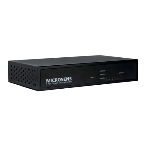
Fast Ethernet 5 Port 10/100Base-TX Switch
MICROSENS
English Operation and Installation manual for
Fast Ethernet 5 Port 10/100Base-TX Switch 15.03.01 MR
1. D
E
Adressierung im Netzwerk
Der Switch verfügt über ein integriertes selbstlernendes Adressmanage-
ment auf Basis Layer 2 (self learning) und unterstützt bis zu 4.096 MAC-
Adressen. Zur Zwischenspeicherung der Pakete und Adressen besitzt
der Switch 1 MBit Arbeitsspeicher. Die Speicherung der Adressen erfolgt
durch eine dynamischen Speicherzuordnung nach dem Empfangen eines
fehlerfreien Paketes. Der Wert für das "Aging" beträgt 300 Sekunden,
d.h. nach 5 Minuten wird eine nicht mehr verwendete Adresse aus dem
Speicher gelöscht.
Address assignment in the network
The switch includes a layer 2 address management (self learning), which
supports up to 4.096 MAC addresses. To store the data and the ad-
dresses the switch has 1 MBit memory. The storage of the addresses is
done in dynamic assignment after receiving a correct data packet. The
value for the “Aging”is 300 seconds. This means that unused addresses
are deleted out of the memory after 5 minutes.
2. D
E
Stromversorgung
Die Stromversorgung erfolgt über ein externes Steckernetzteil 12 V DC /
max. 1 A. Die Steckverbindung der Netzteilzuleitung wird mit dem Switch
verbunden (s. Abb. 2). Aus Gründen der Gewährleistung dürfen nur die
mitgelieferten MICROSENS-Netzteile verwendet werden.
Power supply
The power supply is done by an external power supply 12 V DC / max. 1
A. The plug connector of the power supply is connected to the switch
(see Fig.2). Because of warranty reasons only the included MICROSENS
power supplies has to be used.
3. D
E
Wandmontage (optional)
Mit einer zum Lieferumfang gehörenden Halterung ist zudem eine einfa-
che Wandmontage der Tischgeräte möglich (s. Abb.4).
Wall mounting (optional)
Included accessory is the wall bracket which allows to mount the switch
very easy onto walls (see Fig. 4).
4. D
E
Autonegotiation
Alle Twisted Pair Ports des Gerätes konfigurieren sich durch Autonego-
tiation selbstständig. Dadurch werden die Verbindungen automatisch auf
die größtmögliche Geschwindigkit (10 oder 100 MBit/s bzw. Halb- oder
Vollduplex) eingestellt. Eine manuelle Konfiguration der Twisted Pair
Ports ist nicht erforderlich.
Autonegotiation
All twisted pair ports of the switch are self-configuring with auto-
negotiation. Due to this the connections are automatically configured to
the maximum speed (10/100 MBit/s and full/half duplex). The twisted pair
ports do not require a manual configuration.
5. D
E
Verbindungen über Twisted Pair Ports
Durch die Auto Crossing Funktion der Twisted Pair Ports ist eine Unter-
scheidung der Patchkabel in gekreuzt und 1:1 nicht notwendig. Der
Switch erkennt automatisch die Belegung und stellt sich entsprechend
ein. Somit ist es möglich den Anschluss von Endgeräten und Switches
mit demselben Patchkabel durchzuführen.
Connection at twisted pair ports
Due to the auto crossing function of the twisted pair ports no different
patch cords, crossed or uncrossed, are necessary. The switch is detect-
ing the pinout automatically and configures itself. This allows to connect
end devices and switches with the same patch cord.
Abb./Fig. 1
20,3 mm
Abb./Fig. 2
Masse/Ground
Versorgungsspannung/
Supply voltage
Abb./Fig 3
Stromversorgungsbuchse/
Power supply connector Fast Ethernet Uplink
100Base-FX
Fast Ethernet Anschlüsse/connectors 10/100Base-TX
Autonegotiation/Auto Crossing
Abb./Fig 4
Technische Änderungen vorbehalten / Technical changes reserved
MICROSENS GmbH & Co. KG - Kueferstr. 16 - D-59067 Hamm / Germany - Tel. +49 (0)2381/9452-0 - Fax -100 - www.microsens.com
6. D
E
Glasfaser-Uplink konfigurieren
Mit einem Schalter wird manuell zwischen den Betriebsarten Voll- und
Halbduplexmodus des Glasfaser-Uplinks gewählt. Dieser Schalter befin-
det sich neben dem Glasfaser-Anschluss (s. Abb. 5). Eine LED-Anzeige
zeigt die Betriebsart Vollduplex an (leuchten). Ist die Betriebsart auf
Halbduplex eingestellt fungiert diese LED als Kollisionsanzeige (blinken).
ACHTUNG: Erst im Vollduplexmodus können Längen auf der Glasfaser-
seite von über 412 m realisiert werden. Beachten Sie bitte, dass die
Gegenstelle der Glasfaserseite diese Betriebsart unterstützen muss, da
sonst ein fehlerfreier Betrieb des Netzwerkes nicht gewährleistet ist.
Wichtig: Wird die Betriebsart des Glasfaser-Uplinks während des Betrie-
bes zwischen Voll- und Halbduplex umgeschaltet, muss der Switch
zurückgesetzt werden (Unterbrechung der Stromversorgung). Erst nach
dem Zurücksetzen wird die Glasfaserverbindung neu initialisiert.
Configuration of the fiber uplink port
The duplex mode of the fiber uplink can be set manually with the inte-
grated switch to half or full duplex. This switch is located beside the fiber
port (see Fig. 5). A LED indicates the full duplex mode (LED on). In half
duplex mode this LED has the function of collision indication (flashing).
ATTENTION: Only in the full duplex mode it is possible to realise dis-
tances over 412 m on the fiber side. Please take care that the opposite
side of the connection is working in full duplex mode as well. Otherwise
the correct data transmission is not given.
Important: If the duplex mode is changed during the operation of the
switch, a reset of the switch is necessary. This can be done by
interrupting the power supply. After this the fiber connection is initialized
new.
Abb./Fig. 5
DIP-Schalter für Übertragungsart des Glasfaser-Uplinks/
DIP switch for transmission mode of the fiber uplink
fullduplex
halfduplex
Abb./Fig. 6
MICROSENS
PWR LNK/SPD/ACTLK/AC
FD/HDFD/HD
FX 1 2 3 4
Anzeigen für die Twisted Pair Ports/
LEDs for twisted pair ports
Anzeigen für den Glasfaser-Uplink/
LEDs for fiber uplink
Abb./Fig. 7
LED-Funktionen/LED functions
PWR
Power, betriebsbereit /ready for operation
FD /
HD
An: Verbindung im Vollduplexmodus initialisiert
Blinkend: Kollisionen bei einer Verbindung im
Halbduplexmodus
On: Connection in full duplex mode
Flashing: Collision during a connection in half
duplex mode
LNK /
SPD/
ACT
Gelb: Verbindung des jeweiligen Anschlusses
mit 10 MBit (10Base-T) initialisiert
(nur Port 1-4)
Grün: Verbindung des jeweiligen Anschlusses
mit 100 MBit (100Base-TX bzw.
100Base-FX) initialisiert (Port FX, TP 1-4)
Blinkend: Datenempfang für diese Verbindung
Yellow: Connection of the related port working
with 10 Mbit (10Base-T, only port 1-4)
Green: Connection of the related port working
with 100Mbit (100Base-TX, port FX and TP 1-
4)
Flashing: Data received on this port
FX,
Port
1-4
Pro Port stehen jeweils 2 LEDs zur Verfügung,
die Bedeutung stehen neben den LED-
Anzeigen, FX = Glasfaser-Uplink, Port 1-4 für
RJ45-Buchsen 1-4.
For each port are two LEDS, the function of
these LEDs is printed beside them, FX = fiber
uplink, Port 1-4 for RJ45 connectors 1-4.
7. D
E
8. D
E
LED Anzeigen
Zur Diagnose stehen eine Reihe von LED-Anzeigen zur Verfügung (s.
Abb. 6). Die Bedeutung der Anzeigen wird in Abbildung 7 beschrieben.
Bei den Link-LEDs für die Twisted Pair Ports handelt es sich um zweifar-
bige LED-Anzeigen. Die Farbe Grün steht für eine 100 MBit-Verbindung
und Gelb für eine 10 MBit-Verbindung.
Die LED FDX zeigt die Betriebsart im Vollduplexmodus des jeweiligen
Anschlusses (dauernd leuchtend), im Halbduplexmodus Kollisionen
(blinken) der einzelnen Verbindung an.
LED displays
The switch includes multiple LEDs for diagnostics (see Fig.6). The func-
tion of these LEDs is described in figure 7. The LEDs of the twisted pair
ports are two coloured. The colour green indicates a 100 Mbit connection
and the colour orange indicates a 10 Mbit connection.
The LED FDX indicazes the full duplex mode of the port (LED on), in half
duplex mode this LED has the function of collision indication (flashing).
Sicherheitshinweise
GEFAHR! Optische Komponenten können Laser-Licht ausstrahlen.
ACHTUNG: Infrarot-Strahlung, wie sie für die Datenübertragung im Glas-
faserbereich verwendet wird, ist für das menschliche Auge nicht sichtbar,
kann aber dennoch zu Schädigungen führen.
Um Schädigungen der Augen zu vermeiden niemals direkt mit dem Auge
in die Ausgänge von optischen Komponenten oder Glasfasern sehen.
Erblindungsgefahr! Alle unbenutzten optischen Anschlüsse mit Abdeck-
kappen versehen. Übertragungsstrecke erst in Betrieb nehmen, wenn alle
Verbindungen hergestellt sind. Die in diesem Produkt verwendeten akti-
ven Laser-Komponenten entsprechen der Laser-Klasse 1.
Safety notes
DANGER! Optical components can transmit laser light.
ATTENTION: Infrared light, which is used at the fiber optic data transmis-
sion is not visible for the human eye, but can still cause damages.
To avoid damages at the eyes, never look direct into the outputs of the
optical components or fibers. Danger of going blind! All unused port must
covered with caps. Activate transmission line only when all connections
are done. The active laser components used in this product comply to the
laser class 1.
This manual suits for next models

1

Other Microsens Switch manuals

Microsens MS400863M User manual

Microsens

Microsens MS400863M User manual

Microsens MS450154PM-48 User manual

Microsens

Microsens MS450154PM-48 User manual

Microsens MS400870M Series User manual

Microsens

Microsens MS400870M Series User manual

Microsens MS653410MX User manual

Microsens

Microsens MS653410MX User manual

Microsens MS453526M User manual

Microsens

Microsens MS453526M User manual

Microsens MS453510 User manual

Microsens

Microsens MS453510 User manual

Microsens Profi Line Modular SERIES User manual

Microsens

Microsens Profi Line Modular SERIES User manual

Microsens MS415259M User manual

Microsens

Microsens MS415259M User manual

Microsens MS400863M User manual

Microsens

Microsens MS400863M User manual

Microsens MS657033X User manual

Microsens

Microsens MS657033X User manual

Microsens MS453514M User manual

Microsens

Microsens MS453514M User manual

Microsens MS650850M User guide

Microsens

Microsens MS650850M User guide

Microsens MS400991M User manual

Microsens

Microsens MS400991M User manual

Microsens MS657208PX User manual

Microsens

Microsens MS657208PX User manual

Microsens MS453490M User manual

Microsens

Microsens MS453490M User manual

Microsens MS453510M User manual

Microsens

Microsens MS453510M User manual

Popular Switch manuals by other brands

Cisco 9134 - MDS Multilayer Fabric Switch Release notes

Cisco

Cisco 9134 - MDS Multilayer Fabric Switch Release notes

HP FlexNetwork 7500 Series Configuration guide

HP

HP FlexNetwork 7500 Series Configuration guide

Siemens 3NJ4103-3BF01-0RC0 operating instructions

Siemens

Siemens 3NJ4103-3BF01-0RC0 operating instructions

SignaMax C-100 Series quick start guide

SignaMax

SignaMax C-100 Series quick start guide

HP ProCurve 1600M Management and configuration guide

HP

HP ProCurve 1600M Management and configuration guide

ALFAtron SM62T user manual

ALFAtron

ALFAtron SM62T user manual

iPuray BRT-106 quick start guide

iPuray

iPuray BRT-106 quick start guide

Keysight Technologies 34937A user guide

Keysight Technologies

Keysight Technologies 34937A user guide

Moxa Technologies EtherDevice EDS-4008 Series Quick installation guide

Moxa Technologies

Moxa Technologies EtherDevice EDS-4008 Series Quick installation guide

Linkskey ioPower Specifications

Linkskey

Linkskey ioPower Specifications

NEC SA3500G instruction manual

NEC

NEC SA3500G instruction manual

AETEK H40-022-90-120 Quick installation guide

AETEK

AETEK H40-022-90-120 Quick installation guide

Raritan PARAGON II Series Specifications

Raritan

Raritan PARAGON II Series Specifications

H3C S7500 Series Operation manual

H3C

H3C S7500 Series Operation manual

3Com 3C16710 - OfficeConnect 8/TPM Hub user guide

3Com

3Com 3C16710 - OfficeConnect 8/TPM Hub user guide

MCDonald 6619-029 Replacement instructions

MCDonald

MCDonald 6619-029 Replacement instructions

Accton Technology SuperSmart EtherHub-16se installation manual

Accton Technology

Accton Technology SuperSmart EtherHub-16se installation manual

SecurityMan iCamDVR user manual

SecurityMan

SecurityMan iCamDVR user manual

manuals.online logo
manuals.online logoBrands
  • About & Mission
  • Contact us
  • Privacy Policy
  • Terms and Conditions

Copyright 2025 Manuals.Online. All Rights Reserved.