Microsens MS415259M User manual

MICROSENS GmbH & Co. KG - Kueferstr. 16 -D-59067 Hamm / Germany-Tel. +49 (0)2381/9452-0 - Fax -100 - www.microsens.com
General
Ethernet has been used in the controlling level of industrial applications for many
years. Ethernet is continuing to beat the field bus technologies used to date in coupling
equipment controls, sensors and actors. Process error-tolerant network components are
absolutely essential because the network availability has a direct effect on production.
It is precisely to prevent this that MICROSENS has developed a mechanism for which a
patent is pending that enables the Ethernet network to be reconfigured within
milliseconds if an error occurs.
The switches can be configured and monitored either by SNMP or a PC-based
management tool (Device Manager). In addition to the Device Manager all statuses are
displayed web based using an integrated HTTP server.
In addition to the two SFP ports, which can be operated with Fast Ethernet or Gigabit
Ethernet SFPs, the MICROSENS industrial switches also offer seven 10/100Base-TX
connections for linking such Ethernet terminals as machine controls, network uplinks,
consoles and other network participants and one 10/100/1000Base-T port for a central
uplink connection.
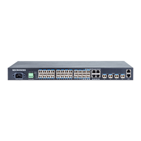
This switch module for the MICROSENS 19“Access Platform offers the central
concentration of the industrial fiber optic ring products.
Features
Gigabit Ethernet Switch Module7x 10/100Base-TX, 1x 10/100/1000Base-T
and 2x SFP slots
Non-blocking architecture, 1 MBit memory
Max. 4096 Mac addresses, 5 minutes aging
Configurable SFP slot for Fast Ethernet or Gigabit Ethernet SFPs
Redundant Ring Functionality
Compatible to the industrial switches with ring funtion
Reconfiguration in < 20 ms
Central power supply with redundancy option
(110 -230V AC, 48V DC or 24V DC)
Integrated agent for network management via PC-Tool, Web, SNMP -
or Telnet-Interface
Full VLAN functionality
Data priotitisation according to IEEE_802.1q
Potential free alarm contact (Relay Contact)
Full compatibility with all modules of the access family
MICROSENS
Gigabit Ethernet Switch Module
1x 10/100/1000Base-T,
7x 10/100Base-TX, 2x SFP-Slots

GBE Switch Module1x 10/100/1000Base-T 7x 10/100Base-TX, 2x SFP Page 2/8
MICROSENS GmbH & Co. KG - Kueferstr. 16 -D-59067 Hamm / Germany - Tel. +49 (0)2381/9452-0 - Fax -100 - www.microsens.com
Technical Specifications
Typ Manageable Gigabit Ethernet Switch module with 2 x SFP
slots, 1x 10/100/1000Base-T and 7x 10/100Base-TX ports for
fault tolerant fiber rings
Fiber type(SFP based) Multimode 62,5/125 or 50/125µm,
Single mode 9/125µm, duplex (optional)
Cable type Shielded Twisted Pair Kabel, 100 Ohm, Categorie 5,
Pinout RJ45 port auto crossover
Data rate 10, 100 and 1000 Mbps
LED displays Power ready for operation
Lnk/Act Link status/Data traffic each Port
Ring Switch is configured into ring mode
RM Switch is ring master
Alarm Fiber uplink interrupted, ring failure or
power supply failure
Power Supply Standard: 18...36 V DC via backplane
Optional: 36...72 V DC via backplane for PoE Option
Fuse 1 A, slow (internal)
Power consumption 8 Watt (typ.)
Dimensions 50 x 108 x 116 mm (wx dx h)
Operationg temp. -20°C to 60°C
Storage temp. -20°C to 80°C
Rel. humidity 5% to 90% non condensing
Management - Configuration with PC based management tool
(not included)
- Support of SNMP-Traps, TELNET, HTTP
Ring function Suitable for master and slave mode, no limitation in number
of ring node, no max. delay

GBE Switch Module1x 10/100/1000Base-T 7x 10/100Base-TX, 2x SFP Page 3/8
MICROSENS GmbH & Co. KG - Kueferstr. 16 -D-59067 Hamm / Germany - Tel. +49 (0)2381/9452-0 - Fax -100 - www.microsens.com
Construction
Gi gab i t Sw it c h
MICROSENS
PWR
RM
ALARM
LN K
LN K
LN K
LN K
Reset
ALARM
10/ 100 /100 0B-T
RING
109
1
3
5
7
2
4
6
8
1
3
5
7
9
10
2
4
6
8
Fig.: Displays and ports
Installation Options
The Optical Crossbar converter module is intended for the installation into a
MICROSENS modular system. It can be combined with all other converter modules of
the same series freely. The current supply is made from a central power supply via
backplane. Together with the power supply (MS416004 and/or MS416004M -
manageable version) maximally 12 modules can be installed into 3HU chassis
(MS416001M) or up to 20 into 4HU chassis front and back (MS416010M).
Optionally a second power supply (MS416004M) for redundancy can be installed. In this
case 10 modules can be used for MS416001M or 18 for MS416010M. During a partial
assembly the unused slots are covered with blind covers (MS416100). The blind covers
do not belong to the scope of supplied with the modular chassis.
Netzteile MS416004M (redundant)
3HE Chassis MS416001M
Port 1:
10/100/1000Base-T
SFP-Slots
Alarm contact

GBE Switch Module1x 10/100/1000Base-T 7x 10/100Base-TX, 2x SFP Page 4/8
MICROSENS GmbH & Co. KG - Kueferstr. 16 -D-59067 Hamm / Germany - Tel. +49 (0)2381/9452-0 - Fax -100 - www.microsens.com
Alarm contact (Relay Contact)
The alarm contact allows the connection of any external alarm system in order to
monitor the operation status. The contact is a 3-ping plug connector at the front of the
switch module. There are both pins, normally open (NO) and normally closed (NC)
available.
The contact is switched in case of a power loss. If the switch is confidured into ring
mode the contact is also switched if the fiber ring is broken in one segment.
Geschaltet wird bei Ausfall der Hauptstromversorgungsspannung. Ist der Switch für
den Ringbetrieb konfiguriert, so wird zusätzlich die Unterbrechung der Glasfaser-
Verbindung signalisiert.
ATTENTION: The maximum power level for this contact is 0.5 A at 60 V DC. It is NOT
allowed to connect devoces with 230 V AC power there.
Transmission Speed
The Twistes Pair ports of the switches are selecting automatically the highest possible
speed by using autonegotiation. The LEDs are indicating the selected mode.
The LEDs are showing the following information.
LED Function
Port 1...8 Link-(on) and activity (blinking) for each copper port
Port 9..10 Link-(on) und activity (blinking) fort he two SFP slots
Ring Switch configured into ring mode
RM Ring-Master (only if ring mode is activated)
Alarm Alarm contact released
Twisted Pair Coinnections
The integrated auto-crossing function of all Twisted-Pair ports makes the use of crossed
patch cables unnecessary. The switch automatically detects the pinout of the connected
cable and adapts the port accordingly. For all connections standard 1:1 Twisted Pair
cables can be used.
The Autonegotiation mechanism detects automatically the speed and transmission
mode (full or half duplex) between connected ports. A manual configuration is not
required but possible via the integrated management.

GBE Switch Module1x 10/100/1000Base-T 7x 10/100Base-TX, 2x SFP Page 5/8
MICROSENS GmbH & Co. KG - Kueferstr. 16 -D-59067 Hamm / Germany - Tel. +49 (0)2381/9452-0 - Fax -100 - www.microsens.com
Management
The integrated http server offers to show status information by using a standard
internet browser. A special configuration is not necessary. Additional to the web based
management the switch offers a MIB to be used in all standardized Network
Management Systems (NMS) supporting SNMPv1 protocol.
With the PC based management tool Device Manager it is possible to configure all
ports of the switch manually. Please refer to the online manual for the Device manager
on the disk.
With this tool it is also possible to do the initial TCP/IP setting (IP address, Gateway etc.).
This configuration can be changed afterwards using the TCP/IP protocol.
Attention: The description for the initial settings can be found in the online manual!
The management information are available inside of the network (inband
management). A special connection is not necessary. Due to this all four twisted pair
ports are available to connect other devices.
With the deactivation of the autonegotiation function of the twisted pair ports the
configuration of the speed to 10 or 100 Mbit/s and full or half duplex mode is done
manually.
Ring Function
The two main SFP ports of the device can be used to build up a ring structure.
Ring structures are commonly used in industrial and telecommunication environments
as they give redundant protection against failures at minimum cabling expense.

GBE Switch Module1x 10/100/1000Base-T 7x 10/100Base-TX, 2x SFP Page 6/8
MICROSENS GmbH & Co. KG - Kueferstr. 16 -D-59067 Hamm / Germany - Tel. +49 (0)2381/9452-0 - Fax -100 - www.microsens.com
In normal operation the ring connection is logically interrupted by monitoring device
(switch configured for Ring Master mode). In case of failure (broken connection or
switch damage) the logically interrupted connection is activated by Ring Master.
A big advantage of this solution is, that no additional central device is necessary for the
redundancy feature. Even if the ring master itself fails, the interruption of the ring
stays at this location.
Normal operation status Data transmission in failure status
Ring Mechanism
The from MICROSENS patented protection mechanism supports the fast
reconfiguration of the data transmission in case of failure of one fiber segment. This
function is a fixed feature of the industrial switch. During this operation one switch is
having the manager function, all other switches are normal ring switches.
Each switch is monitoring the status of the connected fiber segment. In case of failure
the connected switch forwards this information to the ring manager. The ring manager
terminates the interruption of the ring immediately. The data is transmitted in all
directions then. This fast signaling a fast failure detection within a few milliseconds
(depending on the ring size).

GBE Switch Module1x 10/100/1000Base-T 7x 10/100Base-TX, 2x SFP Page 7/8
MICROSENS GmbH & Co. KG - Kueferstr. 16 -D-59067 Hamm / Germany - Tel. +49 (0)2381/9452-0 - Fax -100 - www.microsens.com
Ring Configuration
The configuration of the operating mode for the ring application is done with the
network management.
At the menu point Hardware Setting it is possible to select the two modes master or
slave. The switch which is configured in master mode is doing the ring manager
functions to avoid the multiplication of the data.
If one connection or one device fails this information is forwarded to the ring manager
(master) by a special protocol. The ring manager keeps the operation of the complete
segment up.
Advantage of this solution is that the ring manager itself has not to be redundant,
because if the manager fails the data can not be multiplied. The segments stays under
operation.
To avoid that the signaling in case of failure has no affect on other rings, it is possible
to define different rings with numbers from 0 to 255 by the network management.
All switches with ring functionality are having the management features included and
are offering the detection and signaling of any failure.
With this concept a limitation in regards to the maximum ring length is not given.

GBE Switch Module1x 10/100/1000Base-T 7x 10/100Base-TX, 2x SFP Page 8/8
MICROSENS GmbH & Co. KG - Kueferstr. 16 -D-59067 Hamm / Germany - Tel. +49 (0)2381/9452-0 - Fax -100 - www.microsens.com
Safety Notes
WARNING: Infrared radiation as used for data transmission within the fiber optic,
although invisible to the human eye, can nevertheless cause damage.To avoid damage
to the eyes:
never look straight into the output of fiber optic components –danger of
blinding!
cover all unused optical connections with caps.
commission the transmission link only after completing all connections.
The active laser components used with this product comply with the provisions of
Laser Class 1.
DANGER: Conductive components of power and telecommunications networks can
carry dangerously high voltage. To avoid electric shock:
Do not carry out installation or maintenance work during lightning storms.
All electric installations must be carried out in accordance with local regulations.
Order Information
Art.-No. Description Connectors
MS415259M
10 Port Switch Module, 1x10/100/1000T or
1000BaseX (auto detect),7x10/100TX, Ring-
Redundancy, 2x SFP Ports, manageable
SNMP/web/CLI, VLANs, QoS
8x RJ-45
2x SFP-Slot
1x Alarm Contact
Accessories
Art.-No. Description Connectors
MS100193* SFP, Fast Ethernet
1310 nm Multimode Transceiver, max. 155 Mbps LC duplex
MS100010
SFP, Fast Ethernet
1310 nm Single Mode Transceiver,
max. 155Mbps, min. 25 km
LC duplex
MS100200 SFP, Gigabit Ethernet
850 nm Multimode Transceiver, max. 1,25Gbps LC duplex
MS100210
SFP, Gigabit Ethernet
1310 nm Single Mode Transceiver,
max. 1,25Gbps, min. 10km
LC duplex
Further versions on request.
Software
Art.-No. Description Data Medium
MS200150 Device Manager PC-Software V3.x, universal
MICROSENS Switch Management CD-ROM
MICROSENS reserves theright to make any changes without further notice to any product to improve reliability,function or design. MICROSENS does not assume any
liability arising out of the application or use of any product. 52/07dh
Table of contents
Other Microsens Switch manuals

Microsens
Microsens Profi Line Modular SERIES User manual

Microsens
Microsens MS653410MX User manual

Microsens
Microsens MS400991M User manual

Microsens
Microsens MS657033X User manual

Microsens
Microsens 10Base-TX Specification sheet

Microsens
Microsens MS453510M User manual
Microsens
Microsens MS400863M User manual
Microsens
Microsens MS453514M User manual

Microsens
Microsens MS657208PX User manual

Microsens
Microsens MS400863M User manual