resolution, sampling rate
detection zones
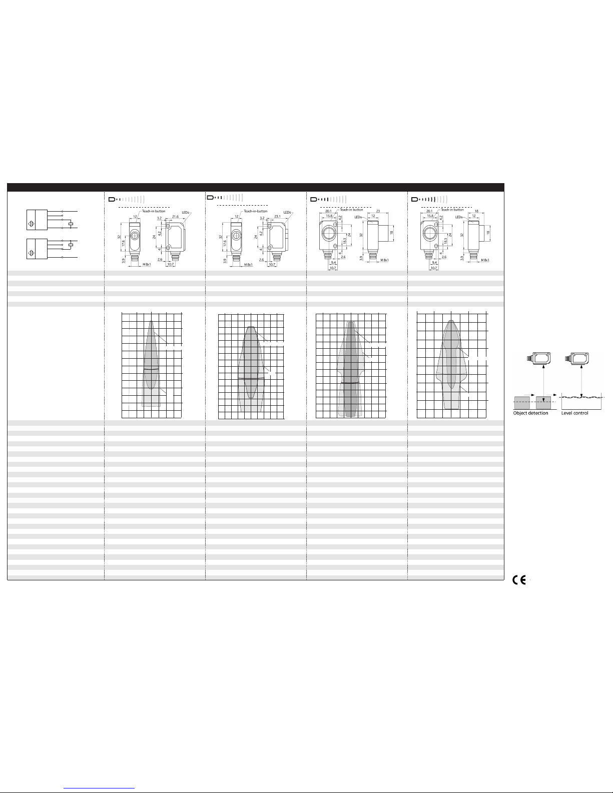
for different objects:
The dark grey areas are determined
with a thin round bar (10 mm dia.)
and indicate the typical operating range
of a sensor. In order to obtain the light grey
areas, a plate (100 x 100 mm) is introduced
into the beam spread from the side.
In doing so, the optimum angle between
plate and sensor is always employed.
This therefore indicates the maximum
detection zone of the sensor.
It is not possible to evaluate ultrasonic
reflections outside this area.
no-load current consumption
temperature drift 0.17 %/K
20 - 30 V DC, reverse polarity protection
temperature drift 0.17 %/K
20 - 30 V DC, reverse polarity protection
class of protection to EN 60 529
ultrasonic transducer: polyurethane foam,
ultrasonic transducer: polyurethane foam,
epoxy resin with glass content
epoxy resin with glass content
LED yellow (state of output)
LED yellow (state of output)
pulse width synchronization signal ti
repetition rate synchronization signal tp
time delay before availability
pnp, UB-2 V, Imax = 200 mA
pnp, UB-2 V, Imax = 200 mA
switchable NOC/NCC, short-circuit-proof
switchable NOC/NCC, short-circuit-proof
npn, -UB+2 V, Imax = 200 mA
npn, -UB+2 V, Imax = 200 mA
switchable NOC/NCC, short-circuit-proof switchable NOC/NCC, short-circuit-proof
temperature drift 0.17 %/K
20 - 30 V DC, reverse polarity protection
temperature drift 0.17 %/K
20 - 30 V DC, reverse polarity protection
ultrasonic transducer: polyurethane foam,
ultrasonic transducer: polyurethane foam,
epoxy resin with glass content
epoxy resin with glass content
LED yellow (state of output)
LED yellow (state of output)
pnp, UB-2 V, Imax = 200 mA
pnp, UB-2 V, Imax = 200 mA
switchable NOC/NCC, short-circuit-proof
switchable NOC/NCC, short-circuit-proof
npn, -UB+2 V, Imax = 200 mA
npn, -UB+2 V, Imax = 200 mA
switchable NOC/NCC, short-circuit-proof switchable NOC/NCC, short-circuit-proof
1
2
4
3
+UB
-UB
Sync
U
1
2
4
3
+UB
-UB
Sync
U
1 pnp switched output
1 npn switched output
8 cm 4 cm 0 cm 4 cm 8 cm
0 cm
4 cm
8 cm
12 cm
16 cm
20 cm
24 cm
Round bar ø 10 mm
Plate
10 cm 5 cm 0 cm 5 cm 10 cm
0 cm
5 cm
10 cm
15 cm
20 cm
25 cm
30 cm
35 cm
Plate
Round bar ø 10 mm
10 cm 5 cm 0 cm 5 cm 10 cm
0 cm
5 cm
10 cm
15 cm
20 cm
25 cm
30 cm
35 cm
Round bar ø 10 mm
Plate
40 cm 20 cm 0 cm 20 cm 40 cm
0 cm
20 cm
40 cm
60 cm
80 cm
100 cm
Round bar ø 10 mm
Plate
microsonic
GmbH
/
Phoenixseestraße
7
/
44263
Dortmund
/
Germany
/
T+49 231 975151-0 / F+49 231 975151-51 / E[email protected] / Wmicrosonic.de The content of this document is subject to technical changes. Specifications in this document are presented in a descriptive way only. They do not warrant any product features.
MV-DO-052889-437422
Notes
The zws sensor has a blind zone,
within which distance measure-
ments are not possible.
In the normal operating mode, an il-
luminated yellow LED signals the
switched output is switched
through.
The standard sensor has no tempe-
rature compensation.
If the object to be sensed moves
into the detection area from the
side, the switching distance should
be set 8-10 % further than the de-
sired switch point to obtain a reli-
able object detection.
If the object moves towards the
sensor (e.g. level control) the detect
point can be taught to the actual
distance at which the sensor has to
switch the output.
Fig. 4: Set the detect point for different
directions of movement of the object
In the »Two-way reflective barrier«
operating mode, the object has to
be within the range of 0-85 % of
the set distance.
If the push-button is not pressed
for 10 minutes during the teach-in
setting, the settings made hitherto
are deleted.
The sensor can be reset to its fac-
tory setting.
2014/30/EU


