manuals.online logo
Brands
  1. Home
  2. •
  3. Brands
  4. •
  5. Microsonic
  6. •
  7. Switch
  8. •
  9. Microsonic IO-Link sks-15/CF/A User manual

Microsonic IO-Link sks-15/CF/A User manual

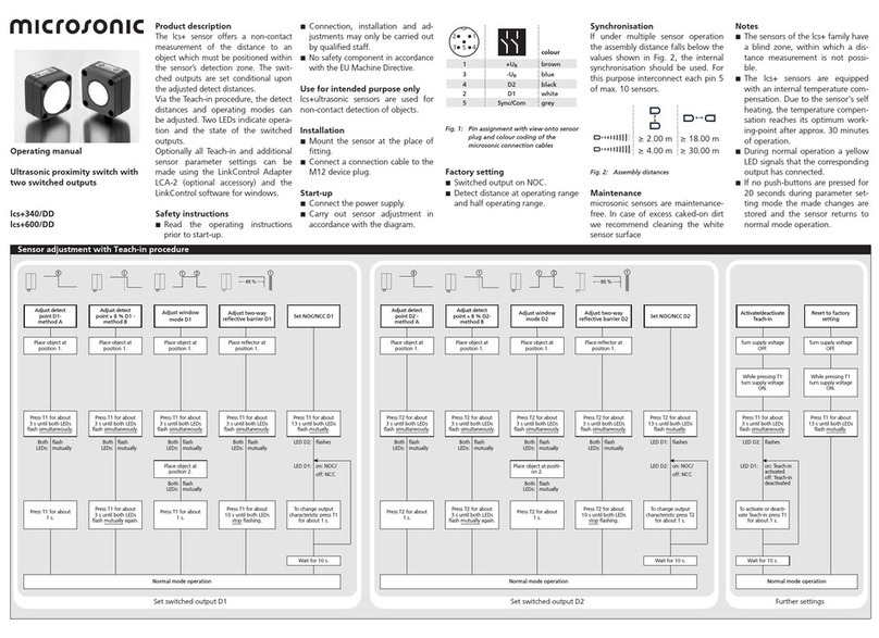
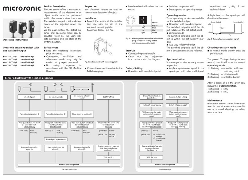
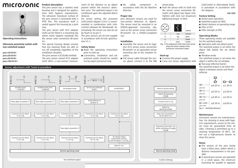
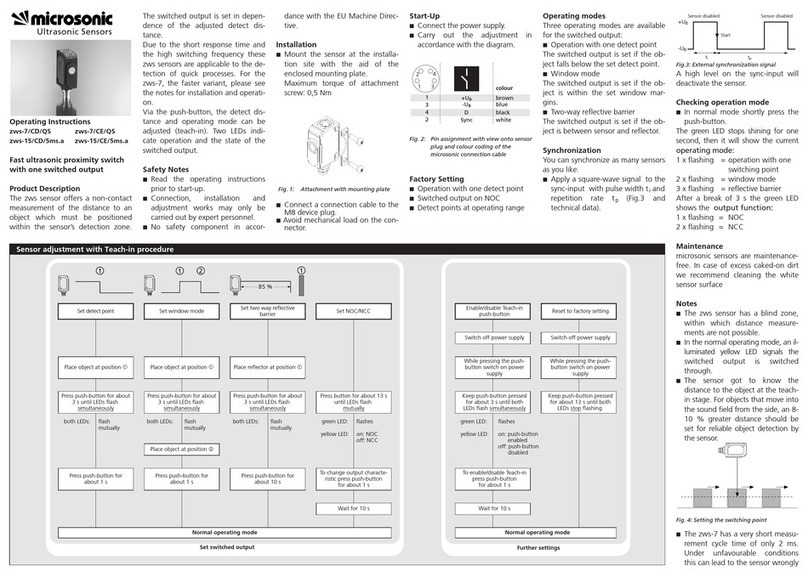
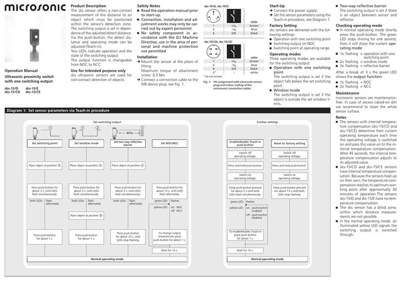
Product Description
The sks sensor offers a non-con-
tactmeasurement of the distance to an
object which must be positioned
within the sensor‘s detection zone.
The switching output is set in depen-
dance of the adjusted detect distance.
Via the push-button, the distance and
operating mode can be adjusted
(Teach-in). Two LEDs indicate the state
of the switching output.
The output function is changeable
from NOC to NCC.
IO-Link
The sks sensor is IO-Link-capable in
accordance with IO-Link specication
V1.1 and supports Smart Sensor Pro-
le like Digital Measuring Sensor.
Safety Notes
Ԏ
Read the operation manual prior
to start-up.
ԎConnection, installation and ad-
justment works may only be car-
ried out by expert personnel.
Ԏ
No safety component in ac-
cordance with the EU Machine
Directive, use in the area of per-
sonal and machine protection
not permitted
Use for intended purpose only
sks ultrasonic sensors are used for
non-contact detection of objects.
Installation
Î
Mount the sensor at the place of
tting.
Maximum torque of attachment
screw: 0,5 Nm.
ÎConnect a connection cable to the
M8 device plug, see Fig.1.
1
2
3
4
colour
1 +UBbrown
3 –UBblue
4 F black
2*)– white
*) do not connect
Fig.1: Pin assignment with view onto sensor
plug and colour coding of the
microsonic connection cables
Start-Up
ÎConnect the power supply.
Î
Set the sensor parameters using the
Teach-in procedure, see Diagram1.
Factory Setting
Ԏ
Operating with one switching point
ԎSwitching output on NOC
Ԏ
Switching points at operating range
ԎFilter F01
ԎFilter strength P00
Operating modes
Three operating modes are available
for the switching output:
Ԏ
Operation with one switching
point
The switching output is set if the
object falls below the set switching
point.
ԎWindow mode
The switching output is set if the
object is inside the set window li-
mits.
ԎTwo-way reective barrier
The switching output is set if there
is an object between sensor and
reector.
Checking operating mode
Î
In normal operating mode shortly
press the push-button. The green
LED stops shining for one second,
then it will show the current ope-
rating mode:
Ԏ1x ashing = operation with one
switching point
Ԏ2x ashing = window mode
Ԏ3x ashing =reective barrier
After a break of 3 s the green LED
shows the output function:
Ԏ1x ashing =NOC
Ԏ2x ashing =NCC
Maintenance
microsonic sensors are maintenance-
free. In case of excess caked-on dirt
we recommend to clean the white
sensor surface.
Notes
Ԏ
Every time the power supply is swit-
ched on, the sensor detects its ac-
tual operating temperature and
transmits it to the internal tempera-
ture compensation. The adjusted
value is taken over after 45 seconds.
Ԏ
If the sensor was switched off for at
least 30 minutes and after power
on the the switching output is not
set for 30 minutes a new adjust-
ment of the internal temperature
compensation to the actual moun-
ting conditions takes place.
Ԏ
The sks sensor has a blind zone
whitin which distance measure-
ments are not possible.
ԎIn the normal operating mode, an
illuminated yellow LED signals the
switching output is switched
through.
Ԏ
In the »Set switching point – me-
thod A« Teach-in procedure the
actual distance to the object is
taught to the sensor as the swit-
ching point. If the object moves
towards the sensor (e.g. with level
control) then the taught distance is
the level at which the sensor has to
switch the output (see Fig.2).
Diagram1:  Set sensor parameters via Teach-in procedure
Press push-button for
about 3 s, until LEDs
flash simultaneously.
Press push-button for
about 3 s, until LEDs
flash simultaneously.
Press push-button for
about 3 s, until LEDs
flash simultaneously.
Press push-button for
about 13 s, until LEDs
flash alternately.
Press push-button
for about 1 s.
Press push-button
for about 1 s.
Press push-button for
about 10 s, until both
LEDs stop flashing.
Press push-button for
about 3 s, until both LEDs
flash alternately.
Place object at position .
1Place object at position .
1
Place object at position .
2
Wait for 10 s.
To change output
characteristic press
push-button for about 1 s.
Normal operating mode
Set switching outputs
Set window mode Set NOC/NCC
and twin mode 1)
Set switching point
– method A Set switching point +8 %
– method B Set two way reflective
barrier
both LEDs: flash
alternately flash
alternately flash
alternately flash
alternately
Press push-button for
about 3 s, until LEDs
flash simultaneously.
Place object at position .
1
both LEDs: both LEDs: both LEDs: green LED: flashes
yellow LED: on:
off: NCC
NOC
11 2
%92
1
1
Reset to factory setting
Wait for 10 s.
Normal operating mode
Further settings
Switch off
operating voltage.
Switch on
operating voltage.
Switch on
operating voltage.
Switch off
operating voltage.
Enable/disable Teach-in
push-button
To enable/disable Teach-in
press push-button
for about 1 s.
Press and hold push-button. Press and hold push-button.
Keep push-button pressed
for about 3 s until both
LEDs flash simultaneously.
Keep push-button pressed
for about 13 s until only the
yellow LED flashes.
flashesgreen LED:
on:
off:
push-button
enabled
push-button
disabled
yellow LED:
Operation Manual
Ultrasonic proximity switch
with one switching output
sks-15/CF/A
Technical data
+U
B
–U
B
1
4
2
3
UF
sks-15...
Teach-in-
button
2x threaded
bush M3
LEDs
13.9
15.2
3.8
32.9
9
16.1 12.1
16.7
M8x
1
blind zone 20 mm
operating range 150 mm
maximum range 250 mm
angle of beam spread see detection zone
transducer frequency 380 kHz
resolution 0.10 mm
reproducibility ±0.15 %
detection zones
for different objects:
The dark grey areas represent the
zone where it is easy to recognise
the normal reector (round bar).
This indicates the typical opera-
ting range of the sensors. The
light grey areas represent the
zone where a very large reector
– for instance a plate – can still
be recognised. The requirement
here is for an optimum alignment
to the sensor. It is not possible to
evaluate ultrasonic reections
outside this area.
4 cm 0 cm 4 cm 8 cm8 cm
0 cm
4 cm
8 cm
12 cm
16 cm
20 cm
24 cm
Plate
Round bar ø 10 mm
accuracy Temperature drift 0.17 %/K
operating voltage UB20 to 30 V DC,
reverse polarity protection (Class 2)
voltage ripple ±10 %
no-load current consumption <30 mA
housing ABS
ultrasonic transducer: polyurethane foam,
epoxy resin with glass content
class of protection to EN 60529 IP 67
norm conformity EN 60947-5-2
type of connection 4-pin M8 initiator plug
scope of settings Teach-in-Taster
indicators LED green (operation)
LED yellow (state of output)
operating temperature –25 to +70 °C
storage temperature –40 to +85 °C
weight 8 g
switching hysteresis 2 mm
switching frequency 25 Hz
response time 32 ms
switch-off delay time <300 ms
order no. sks-15/CF/A
switching output Push pull, UB–3 V, –UB+3 V, Imax = 100 mA
switchable NOC/NCC, short-circuit-proof
microsonic GmbH / Phoenixseestraße 7 / 44263 Dortmund / Germany / T +49 231 975151-0 / F +49 231 975151-51 / E [email protected] / W microsonic.de
The content of this document is subject to technical changes. Specications in this document are presented in a descriptive way only. They do not warrant any product features.
ԎIf the object to be scanned moves
into the detection area from the
side, the »Set switching point +8 %
– method B« Teach-in procedure
should be used. In this way the swit-
ching distance is set 8 % further
than the actual measured distance
to the object. This ensures a reliable
switching distance even if the
height of the objects varies slightly,
(see Fig.2).
Level control Object detection
Fig.2: Teach-in for dierent directions of
movement of the obcject
ԎIn the »Two-way reective barrier«
operating mode, the object has to
be within the range of 0-92 % of
the set distance.
Ԏ
If the push button is not pressed for
30 seconds during the Teach-in set-
ting, the settings made hitherto are
deleted.
ԎThe sensor can be reset to its facto-
ry setting (see »Further settings«,
Diagram1).
ԎThe current IODD library and infor-
mation on start-up with IO-Link
are available on the Internet at
microsonic.de/en/sks.
Enclosure Type 1
For use only in industrial
machinery NFPA 79 applications.
The proximity switches shall be used with a Listed
(CYJV/7) cable/connector assembly rated mini-
mum 32 Vdc, minimum 290 mA, in the nal in-
stallation.
*B13589*
MV-DO-198526-842828

Other Microsonic Switch manuals

Microsonic sks-15/CF/A User manual

Microsonic

Microsonic sks-15/CF/A User manual

Microsonic lcs+340/DD User manual

Microsonic

Microsonic lcs+340/DD User manual

Microsonic pmsplus15/CF/A1 User manual

Microsonic

Microsonic pmsplus15/CF/A1 User manual

Microsonic sks-15/D User manual

Microsonic

Microsonic sks-15/D User manual

Microsonic sks-15/CI User manual

Microsonic

Microsonic sks-15/CI User manual

Microsonic zws-15/CD/QS User manual

Microsonic

Microsonic zws-15/CD/QS User manual

Microsonic zws-7/CD/QS User manual

Microsonic

Microsonic zws-7/CD/QS User manual

Popular Switch manuals by other brands

Crestron HD-MD8X8-4KZ-E Configuration guide

Crestron

Crestron HD-MD8X8-4KZ-E Configuration guide

Festo SRBF-C series operating instructions

Festo

Festo SRBF-C series operating instructions

Juniper EX Series quick start guide

Juniper

Juniper EX Series quick start guide

Penn F261 Series installation guide

Penn

Penn F261 Series installation guide

Pulsar SF108 quick start guide

Pulsar

Pulsar SF108 quick start guide

Cisco OL-12518-01 supplementary guide

Cisco

Cisco OL-12518-01 supplementary guide

H3C S9500E Series installation guide

H3C

H3C S9500E Series installation guide

Belkin 16-Port Gigabit Switch user manual

Belkin

Belkin 16-Port Gigabit Switch user manual

Allied Telesis AT-8900 SERIES Troubleshooting

Allied Telesis

Allied Telesis AT-8900 SERIES Troubleshooting

Garland GAA10G20AC user guide

Garland

Garland GAA10G20AC user guide

Endress+Hauser Ceraphant T PTC31 operating instructions

Endress+Hauser

Endress+Hauser Ceraphant T PTC31 operating instructions

Ruijie RG-CS83-24GT4XS-PD Hardware  installation and reference guide

Ruijie

Ruijie RG-CS83-24GT4XS-PD Hardware installation and reference guide

D-Link EasySmart DES-1100-16 Firmware release notes

D-Link

D-Link EasySmart DES-1100-16 Firmware release notes

LevelOne OfficeCon FSW-2420TX user guide

LevelOne

LevelOne OfficeCon FSW-2420TX user guide

TRENDnet TE100-S24R Specifications

TRENDnet

TRENDnet TE100-S24R Specifications

D-Link DES-3250TG user guide

D-Link

D-Link DES-3250TG user guide

GEM 4216 Installation, operating and maintenance instructions

GEM

GEM 4216 Installation, operating and maintenance instructions

Comtrol RocketLinx ES7528 user guide

Comtrol

Comtrol RocketLinx ES7528 user guide

manuals.online logo
manuals.online logoBrands
  • About & Mission
  • Contact us
  • Privacy Policy
  • Terms and Conditions

Copyright 2025 Manuals.Online. All Rights Reserved.