Woodward SPM-D10B/PSY5 User manual

37231D
f - f + V - V +
Closed
Connect
Enable
Digit Cursor
Reset
Display
Enter
-180° +180°
Closed
Synchronizing System
Enable
Connect
f - f + V - V +
SPM-D
Manual
Version 1.1xx
Manual 37231D
SPM-D10B/PSY5
Synchronizing Unit

Manual 37231D SPM-D10B/PSY5 - Synchronizing Unit
Page 2/69 © Woodward
WARNING
Read this entire manual and all other publications pertaining to the work to be performed before in-
stalling, operating, or servicing this equipment. Practice all plant and safety instructions and precau-
tions. Failure to follow instructions can cause personal injury and/or property damage.
The engine, turbine, or other type of prime mover should be equipped with an overspeed
(overtemperature, or overpressure, where applicable) shutdown device(s), that operates totally inde-
pendently of the prime mover control device(s) to protect against runaway or damage to the engine,
turbine, or other type of prime mover with possible personal injury or loss of life should the mechani-
cal-hydraulic governor(s) or electric control(s), the actuator(s), fuel control(s), the driving mecha-
nism(s), the linkage(s), or the controlled device(s) fail.
Any unauthorized modifications to or use of this equipment outside its specified mechanical, electri-
cal, or other operating limits may cause personal injury and/or property damage, including damage to
the equipment. Any such unauthorized modifications: (i) constitute "misuse" and/or "negligence" with-
in the meaning of the product warranty thereby excluding warranty coverage for any resulting damage,
and (ii) invalidate product certifications or listings.
CAUTION
To prevent damage to a control system that uses an alternator or battery-charging device, make sure
the charging device is turned off before disconnecting the battery from the system.
Electronic controls contain static-sensitive parts. Observe the following precautions to prevent dam-
age to these parts.
•
Discharge body static before handling the control (with power to the control turned off, contact a
grounded surface and maintain contact while handling the control).
•
Avoid all plastic, vinyl, and Styrofoam (except antistatic versions) around printed circuit boards.
•
Do not touch the components or conductors on a printed circuit board with your hands or with
conductive devices.
OUT-OF-DATE PUBLICATION
This publication may have been revised or updated since this copy was produced. To verify that you
have the latest revision, be sure to check the Woodward website.
The revision level is shown at the bottom of the front cover after the publication number. The latest
version of most publications is available at:
http://www.woodward.com/publications
If your publication is not there, please contact your customer service representative to get the latest
copy.
Important definitions
WARNING
Indicates a potentially hazardous situation that, if not avoided, could result in death or serious injury.
CAUTION
Indicates a potentially hazardous situation that, if not avoided, could result in damage to equipment.
NOTE
Provides other helpful information that does not fall under the warning or caution categories.
Woodward reserves the right to update any portion of this publication at any time. Information provided by Woodward is believed to be
correct and reliable. However, Woodward assumes no responsibility unless otherwise expressly undertaken.
© Woodward
All Rights Reserved.

Manual 37231D SPM-D10B/PSY5 - Synchronizing Unit
© Woodward Page 3/69
Revision History
Rev.
Date
Editor
Changes
C
08-11-14
TP
Release
D
2014-09-23
GG
Voltage range changed from “90 to 250 Vac/dc” to “90 to 250 Vac”.
Protection (from back) changed from “IP21” to “IP20”.
Content
CHAPTER 1. GENERAL INFORMATION ....................................................................... 6
CHAPTER 2. ELECTROSTATIC DISCHARGE AWARENESS ............................................ 7
CHAPTER 3. INSTALLATION ...................................................................................... 8
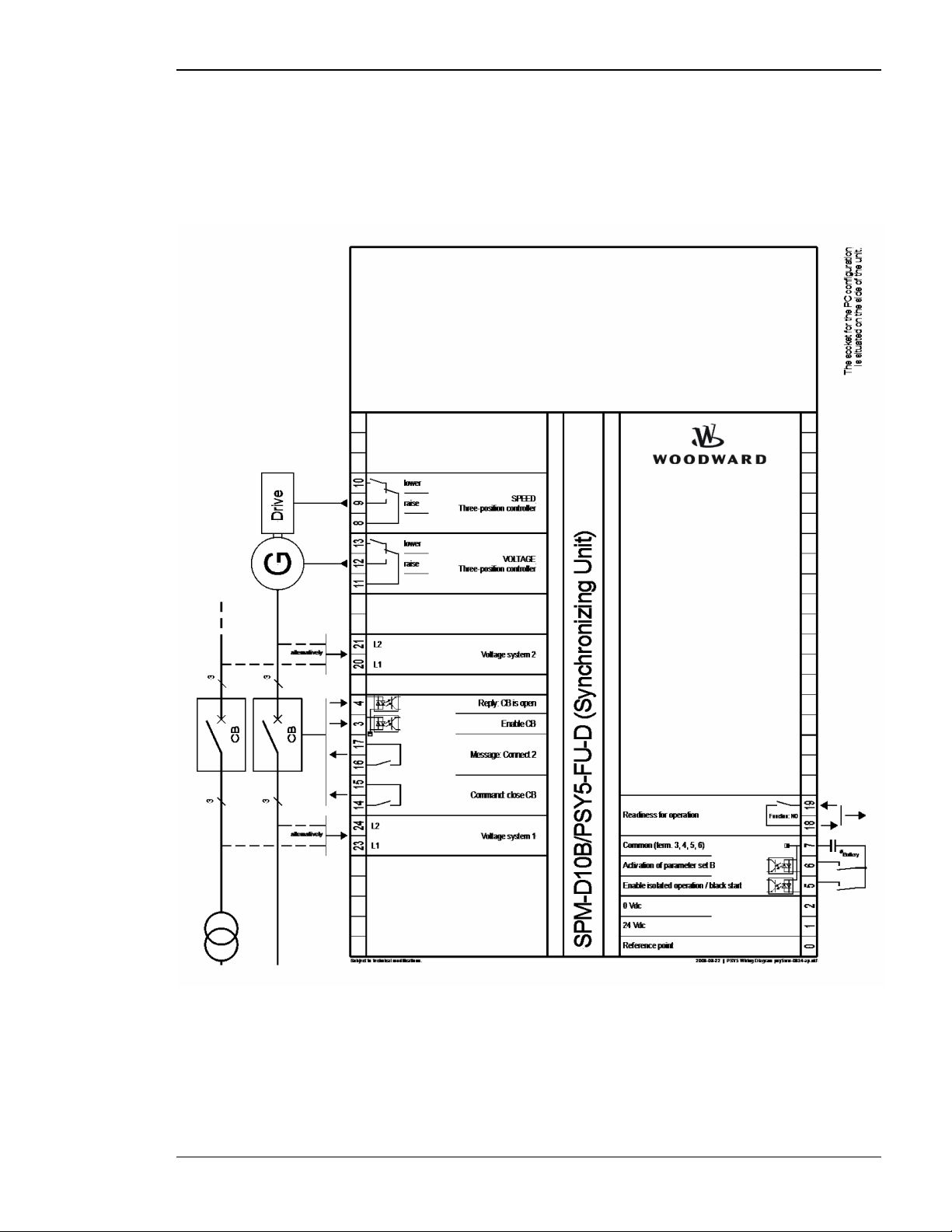
Wiring diagram ....................................................................................................................... 9
SPM-D10B/PSY5-FU-D (power supply: 24 Vdc) ......................................................... 9
SPM-D10B/PSY5-FU-A (power supply: 24 Vdc)........................................................ 10
SPM-D10B/PSY5-FU-D-W (power supply: 90..250 Vac)........................................... 11
SPM-D10B/PSY5-FU-A-W (power supply: 90..250 Vac)........................................... 12
Reference point .................................................................................................................... 13
Power supply (standard & SPM-D10B/PSY5-..W) ............................................................... 13
Measuring inputs .................................................................................................................. 14
System 2 .................................................................................................................... 14
System 1 .................................................................................................................... 15
Discrete inputs...................................................................................................................... 16
Relay outputs........................................................................................................................ 17
Controller outputs ................................................................................................................. 18
SPM-D10B/PSY5-..D.. ............................................................................................... 18
SPM-D10B/PSY5-..A.. ............................................................................................... 19
CHAPTER 4. DESCRIPTION OF FUNCTIONS .............................................................. 21
Functionality ......................................................................................................................... 21
Function tables........................................................................................................... 21
Additional conditions .................................................................................................. 22
Control inputs ....................................................................................................................... 23
Isolation of the power supply from the discrete inputs ......................................................... 23
Operating conditions ............................................................................................................ 24
No load control ........................................................................................................... 24
Synchronizing............................................................................................................. 24
Synch check............................................................................................................... 25
Isolated operation....................................................................................................... 25
Closing the CB without synchronization (black start) ................................................. 25
LED "Closed" flashes ................................................................................................. 26
Control outputs ..................................................................................................................... 26
Analog controller outputs...................................................................................................... 27
CHAPTER 5. DISPLAY AND OPERATING ELEMENTS .................................................. 30
Brief explanation of the LEDs and push buttons .................................................................. 31
LEDs .......................................................................................................................... 31
Buttons ....................................................................................................................... 31
Others ........................................................................................................................ 31
LEDs..................................................................................................................................... 32
Push buttons ........................................................................................................................ 34
LC display............................................................................................................................. 35

Manual 37231D SPM-D10B/PSY5 - Synchronizing Unit
Page 4/69 © Woodward
Display monitoring in automatic mode: Double voltage / frequency display.............. 35
Display monitoring in automatic mode: Alarm indication ........................................... 35
CHAPTER 6. CONFIGURATION................................................................................. 36
Configure basic data............................................................................................................ 36
Password protection .................................................................................................. 37
Direct Configuration................................................................................................... 38
Configure basic settings ...................................................................................................... 39
Configure controller ............................................................................................................. 40
No load control .......................................................................................................... 40
Frequency controller.................................................................................................. 41
Voltage controller....................................................................................................... 46
Synchronization ......................................................................................................... 51
Synchronization time monitoring................................................................................ 53
Black start.................................................................................................................. 54
Relay output 16-17 .................................................................................................... 55
Password configuration ....................................................................................................... 56
CHAPTER 7. COMMISSIONING ................................................................................. 57
Product Service Options ...................................................................................................... 64
Returning Equipment For Repair ......................................................................................... 64
Packing A Control...................................................................................................... 65
Return Authorization Number RAN ........................................................................... 65
Replacement Parts .............................................................................................................. 65
How To Contact Woodward................................................................................................. 66
Engineering Services ........................................................................................................... 67
Technical Assistance ........................................................................................................... 68

Manual 37231D SPM-D10B/PSY5 - Synchronizing Unit
© Woodward Page 5/69
Illustrations and Tables
Illustrations
Figure 3-1: Wiring diagram SPM-D10B/PSY5-FU-D.......................................................................................... 9
Figure 3-2: Wiring diagram SPM-D10B/PSY5-FU-A........................................................................................ 10
Figure 3-3: Wiring diagram SPM-D10B/PSY5-FU-D-W................................................................................... 11
Figure 3-4: Wiring diagram SPM-D10B/PSY5-FU-A-W................................................................................... 12
Figure 3-5: Reference point ................................................................................................................................ 13
Figure 3-6: Power supply (24 Vdc, standard) ..................................................................................................... 13
Figure 3-7: Power supply (90..250 Vac, SPM-D10B/PSY5-..W)....................................................................... 13
Figure 3-8: Measuring inputs – voltage system 2 ............................................................................................... 14
Figure 3-9: Measuring inputs – Voltage system 1............................................................................................... 15
Figure 3-10: Discrete inputs................................................................................................................................ 16
Figure 3-11: Relay outputs – control outputs I (CB control) .............................................................................. 17
Figure 3-12: Relay outputs – control outputs II (messages)................................................................................ 17
Figure 3-13: Controller - SPM-D10B/PSY5-..D.. – three position controller .................................................... 18
Figure 3-14: Controller - SPM-D10B/PSY5-..A.. – three position controller .................................................... 19
Figure 3-15: Controller - SPM-D10B/PSY5-..A.. – analog controller output - speed/frequency ....................... 20
Figure 3-16: Controller - SPM-D10B/PSY5-..A.. – analog controller output - voltage ..................................... 20
Figure 4-1: Control loop ..................................................................................................................................... 27
Figure 4-2: Step response (example)................................................................................................................... 27
Figure 4-3: Step response – controller set-up ..................................................................................................... 29
Figure 5-1: Front foil .......................................................................................................................................... 30
Figure 7-1: Dimensions....................................................................................................................................... 59
Tables
Table 4-1: Operating conditions ......................................................................................................................... 21
Table 4-2: Operating conditions - terms ............................................................................................................. 22

Manual 37231D SPM-D10B/PSY5 - Synchronizing Unit
Page 6/69 © Woodward
Chapter 1.
General Information
Intended Use The unit must only be operated for the uses described in this manual. The prerequisite for a proper
and safe operation of the product is correct transportation, storage, and installation as well as careful operation
and maintenance.
NOTE
This manual has been developed for a unit fitted with all available options. Inputs/outputs, func-
tions, configuration screens and other details described, which do not exist on your unit may be
ignored.
The present manual has been prepared to enable the installation and commissioning of the unit.
On account of the large variety of parameter settings, it is not possible to cover every possible
combination. The manual are therefore only a guide. In case of incorrect entries or a total loss of
functions, the default settings can be taken from the enclosed list of parameters.

Manual 37231D SPM-D10B/PSY5 - Synchronizing Unit
© Woodward Page 7/69
Chapter 2.
Electrostatic Discharge Awareness
All electronic equipment is static-sensitive, some components more than others. To protect these components
from static damage, you must take special precautions to minimize or eliminate electrostatic discharges.
Follow these precautions when working with or near the control.
1. Before doing maintenance on the electronic control, discharge the static electricity on your body to ground
by touching and holding a grounded metal object (pipes, cabinets, equipment, etc.).
2. Avoid the build-up of static electricity on your body by not wearing clothing made of synthetic materials.
Wear cotton or cotton-blend materials as much as possible because these do not store static electric charg-
es as easily as synthetics.
3. Keep plastic, vinyl, and Styrofoam materials (such as plastic or Styrofoam cups, cigarette packages, cello-
phane wrappers, vinyl books or folders, plastic bottles, etc.) away from the control, modules, and work ar-
ea as much as possible.
4. Opening the control cover may void the unit warranty.
Do not remove the printed circuit board (PCB) from the control cabinet unless absolutely necessary. If you
must remove the PCB from the control cabinet, follow these precautions:
•Ensure that the device is completely voltage-free (all connectors have to be disconnected).
•Do not touch any part of the PCB except the edges.
•Do not touch the electrical conductors, connectors, or components with conductive devices or with bare
hands.
•When replacing a PCB, keep the new PCB in the plastic antistatic protective bag it comes in until you
are ready to install it. Immediately after removing the old PCB from the control cabinet, place it in the
antistatic protective bag.
CAUTION
To prevent damage to electronic components caused by improper handling, read and observe the pre-
cautions in Woodward manual 82715, Guide for Handling and Protection of Electronic Controls, Print-
ed Circuit Boards, and Modules.
NOTE
The unit is capable to withstand an electrostatic powder coating process with a voltage of up to 85 kV
and a current of up to 40 µA.

Manual 37231D SPM-D10B/PSY5 - Synchronizing Unit
Page 8/69 © Woodward
Chapter 3.
Installation
CAUTION
A circuit breaker must be provided near to the unit and in a position easily accessible to the op-
erator. This must also bear a sign identifying it as an isolating switch for the unit.
NOTE
Inductivities connected (such as coils of operating current or undervoltage tripping units, or
auxiliary or power contacts) must be connected to a suitable interference suppressor.

Manual 37231D SPM-D10B/PSY5 - Synchronizing Unit
© Woodward Page 9/69
Wiring diagram
SPM-D10B/PSY5-FU-D (power supply: 24 Vdc)
Figure 3-1: Wiring diagram SPM-D10B/PSY5-FU-D

Manual 37231D SPM-D10B/PSY5 - Synchronizing Unit
Page 10/69 © Woodward
SPM-D10B/PSY5-FU-A (power supply: 24 Vdc)
Figure 3-2: Wiring diagram SPM-D10B/PSY5-FU-A

Manual 37231D SPM-D10B/PSY5 - Synchronizing Unit
© Woodward Page 11/69
SPM-D10B/PSY5-FU-D-W (power supply: 90..250 Vac)
Figure 3-3: Wiring diagram SPM-D10B/PSY5-FU-D-W

Manual 37231D SPM-D10B/PSY5 - Synchronizing Unit
Page 12/69 © Woodward
SPM-D10B/PSY5-FU-A-W (power supply: 90..250 Vac)
Figure 3-4: Wiring diagram SPM-D10B/PSY5-FU-A-W

Manual 37231D SPM-D10B/PSY5 - Synchronizing Unit
© Woodward Page 13/69
Reference point
0
Reference point
Figure 3-5: Reference point
Terminal
Description
Amax
0
Reference point: Neutral point of the three-phase system or neutral
terminal of the voltage transformer (Measuring reference point);
with three-conductor systems, do not connect
Sold.lug
Power supply (standard & SPM-D10B/PSY5-..W)
24 Vdc (+/-25 %)
1 2
24 Vdc
0 Vdc
Power supply
Standard
Figure 3-6: Power supply (24 Vdc, standard)
Terminal
Description
Amax
Standard
1
+24 Vdc, 10 W
2.5 mm²
2
0 V reference potential
2.5 mm²
Figure 3-7: Power supply (90..250 Vac, SPM-D10B/PSY5-..W)
Terminal
Description
Amax
SPM-D10B/PSY5-..W - wide range power supply
25
90..250 Vac, max. 10 VA
2.5 mm²
27
PE
2.5 mm²
29
0 Vac
2.5 mm²

Manual 37231D SPM-D10B/PSY5 - Synchronizing Unit
Page 14/69 © Woodward
Measuring inputs
NOTE
The SPM-D10B/PSY5 can operate (monitor) only one synchronization point (one power circuit
breaker), because it is a 1-power-circuit-breaker configuration. The voltage at terminals 23/24
(system 1) is the voltage to which the assessment of the synchronization at terminals 20/21 (sys-
tem 2) refers. The synchronization voltage can be, e. g., the mains or busbar voltage.
NOTE
There are generally three different variants for connection of the measuring circuit voltage:
Direct connection to the low voltage system,
Connection to medium voltage via two-pole isolated transformer (e. g. in the case of a
V-connection) and
Connection to medium voltage via single-pole isolated transformer (e. g. Y-connection).
System 2
Voltage
Syst em 2
1
L1
L2
G
21200
MCB
N
L3
L1
L2
GCB
23
Figure 3-8: Measuring inputs – voltage system 2
Note: Connection corresponding to the mains configuration (see wiring diagram).
Terminal
Measurement
Description
Amax
Connection to the measuring circuit voltage corresponding to the variant , or
20
direct or
Transformer
../100 V
Voltage system 2 - L1
2.5 mm²
21
Voltage system 2 - L2
2.5 mm²
0
Reference point: N-terminal of the low voltage
system or star point of the voltage transducer
(measuring reference point);
do not connect in three wire installations
Sold.lug

Manual 37231D SPM-D10B/PSY5 - Synchronizing Unit
© Woodward Page 15/69
System 1
Voltage
System 1
GCB
G
L2
L1
23 24
123
N
L1
L2
L3
231
MCB
Figure 3-9: Measuring inputs – Voltage system 1
Note: Connection corresponding to the mains configuration (see wiring diagram).
Terminal
Measurement
Description
Amax
Connection to the measuring circuit voltage corresponding to variant , or
23
direct
or ../100 V
Voltage system 1 - L1
2.5 mm²
24
Voltage system 1 - L2
2.5 mm²

Manual 37231D SPM-D10B/PSY5 - Synchronizing Unit
Page 16/69 © Woodward
Discrete inputs
CAUTION
Please note that the maximum voltages which may be applied at the discrete inputs are defined
as follows. Voltages higher than those specified destroy the hardware!
•Maximum input range: +/-18..250 Vac.
D
Signal device
CB
Reply CB
Enable CB
Reply: CB is open
BA
18..250 Vac/dc
C
3
Figure 3-10: Discrete inputs
Terminal
Associated
zero-terminal
Description
(acc. DIN 40 719 part 3, 5.8.3)
A
max
Make contact
A
B
3
7
Enable CB
2.5 mm²
5
Enable isolated operation / black start
2.5 mm²
6
Activation of parameter set B
2.5 mm²
Normally closed contact
C
D
4
7
Reply: CB is open
2.5 mm²

Manual 37231D SPM-D10B/PSY5 - Synchronizing Unit
© Woodward Page 17/69
Relay outputs
max. 250 V AC
A
B
external device Relay output
Figure 3-11: Relay outputs – control outputs I (CB control)
Root
Switched
Description
Amax
A
B
14
15
Synchronizing pulse, Command: close CB
2.5 mm²
max. 250 V AC
A
B
external device Relay output
Figure 3-12: Relay outputs – control outputs II (messages)
Root
Switched
Description
Amax
A
B
Note: The relays close when the function is fulfilled.
16
17
Message: Connect 2
2.5 mm²
18
19
Readiness for operation
2.5 mm²

Manual 37231D SPM-D10B/PSY5 - Synchronizing Unit
Page 18/69 © Woodward
Controller outputs
The SPM-D10B/PSY5-FU-D.. is equipped with two three-position controllers for voltage and frequency (made of
a form C and form A relay). With the version SPM-D10B/PSY5-FU-A different controller output signals can be
selected by configuration, which are connected in different ways.
SPM-D10B/PSY5-..D..
max. 250 Vac
11 12 13
Voltage
controller
Common
Raise
Lower
Voltage controller
8
Common
Speed
controller Speed / frequency
controller
910
Lower
Raise
Figure 3-13: Controller - SPM-D10B/PSY5-..D.. – three position controller
Terminal
Description
Amax
8
common
Speed/frequency controller
2.5 mm²
9
higher
2.5 mm²
10
lower
2.5 mm²
11
common
Voltage controller
2.5 mm²
12
higher
2.5 mm²
13
lower
2.5 mm²

Manual 37231D SPM-D10B/PSY5 - Synchronizing Unit
© Woodward Page 19/69
SPM-D10B/PSY5-..A..
The SPM-D10B/PSY5-..A.. has controller outputs for the following signals which can be changed by configura-
tion as well as over an external bridge.
Versions
- Three-position controller via relay manager
- Control of n/f: Parameter "f-controller type" = THREESTEP
n+/f+ = Relay connected to terminals 45/46
n-/f- = Relay connected to terminals 47/48
- Control of V: parameter "v-controller type" = THREESTEP
V+ = Relay connected to terminals 45/46
V- = Relay connected to terminals 47/48
- Analog controller output
- Control of n/f: Parameter "f-controller type" = ANALOG
Current output (mA) = no external bridge/jumper necessary
Voltage output (V) = external bridge/jumper between 8/9
Connect the Controller to terminals 9/10
- Control of V: Parameter "v-controller type" = ANALOG
Current output (mA) = no external bridge/jumper necessary
Voltage output (V) = external bridge/jumper between 11/12
Connect the controller to terminals 12/13
- PWM controller output
- Control of n/f: Parameter "f-controller type" = PWM
PWM output = external bridge/jumper between 8/9
Connect the controller to terminals 9/10
Connection of the controllers
Setting: 'THREESTEP' (three-position controller)
The relay has to be decoupled.
AB
Relay output
max. 250 Vac
Figure 3-14: Controller - SPM-D10B/PSY5-..A.. – three position controller
Terminal
Description
Amax
45
raise Speed / Frequency controller
or
Voltage controller
2.5 mm²
46
2.5 mm²
47
lower
2.5 mm²
48
2.5 mm²
NOTE
In the SPM-D10B/PSY5-FU-A-W no relays for three-point controller are present!

Manual 37231D SPM-D10B/PSY5 - Synchronizing Unit
Page 20/69 © Woodward
Setting: 'ANALOG' and 'PWM' (analog controller) – Frequency controller
GND
Speed / power
controller
8109
GND
PWM
Speed
Governor
GND
PWM PWM
Speed / power
controller
8
U
109
A
Voltage
Speed
Governor
A
U
GND
Speed / power
controller
8
A
I
109
GND
Current
Speed
Governor
A
I
GND
N/C
Figure 3-15: Controller - SPM-D10B/PSY5-..A.. – analog controller output - speed/frequency
Type
Terminal
Description
Amax
I
Current
8
IA
Speed controller / Frequency controller
2,5 mm²
9
2,5 mm²
10
GND
2,5 mm²
U
Voltage
8
2,5 mm²
9
UA
2,5 mm²
10
GND
2,5 mm²
PWM
8
2,5 mm²
9
PWM
2,5 mm²
10
GND
2,5 mm²
Setting: 'ANALOG' (analog controller) – voltage controller
Voltage / re-active
power controller
11
A
I
13
12
GND
Current
AVR
A
I
N/C
GND
Voltage / re-active
power controller
11
U
1312
A
Voltage
A
U
GND GND
AVR
Figure 3-16: Controller - SPM-D10B/PSY5-..A.. – analog controller output - voltage
Type
Terminal
Description
Amax
I
Current
11
IA
Voltage controller
2.5 mm²
12
2.5 mm²
13
GND
2.5 mm²
U
Voltage
11
2.5 mm²
12
UA
2.5 mm²
13
GND
2.5 mm²
This manual suits for next models
4
Table of contents
Other Woodward Recording Equipment manuals