Yaesu FT-950 User manual

HF/50 MH
Z
T
RANSCEIVER
FT-950
O
PERATING
M
ANUAL
VERTEX STANDARD CO., LTD.
4-8-8 Nakameguro, Meguro-Ku, Tokyo 153-8644, Japan
VERTEX STANDARD
US Headquarters
10900 Walker Street, Cypress, CA 90630, U.S.A.
YAESU EUROPE B.V.
P.O. Box 75525, 1118 ZN Schiphol, The Netherlands
YAESU UK LTD.
Unit 12, Sun Valley Business Park, Winnall Close
Winchester, Hampshire, SO23 0LB, U.K.
VERTEX STANDARD HK LTD.
Unit 5, 20/F., Seaview Centre, 139-141 Hoi Bun Road,
Kwun Tong, Kowloon, Hong Kong
VERTEX STANDARD (AUSTRALIA)PTY., LTD.
Normanby Business Park, Unit 14/45 Normanby Road
Notting Hill 3168, Victoria, Australia

ABOUT THIS MANUAL . . .
The FT-950 is a leading-edge transceiver with a number of new and exciting features, some of which may be unfamiliar to
you. In order to gain the most enjoyment and operating efficiency from your FT-950, we recommend that you read this
manual in its entirety, and keep it handy for reference as you explore the many capabilities of your new transceiver.
Before using your FT-950, be sure to read and follow the instructions in the “Before You Begin” section of this manual.

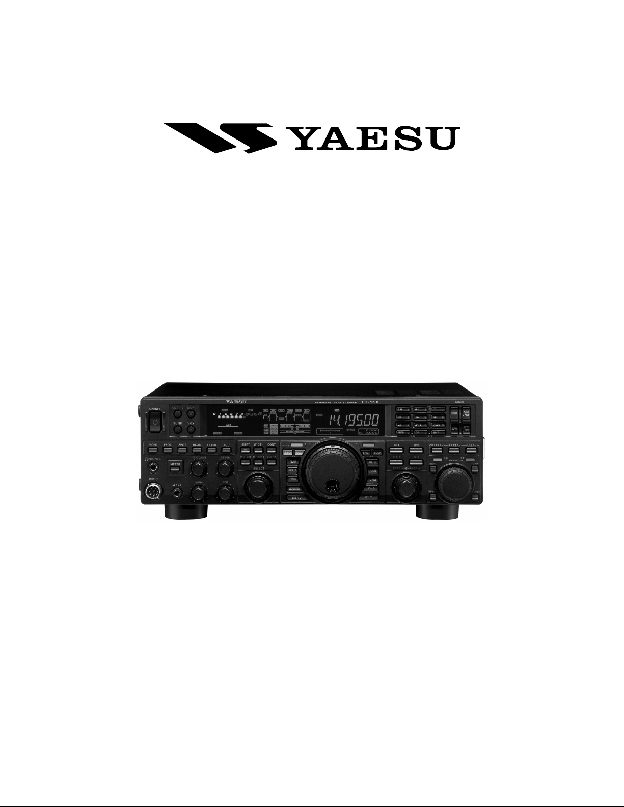
Page 1FT-950 OPERATING MANUAL
GENERAL DESCRIPTION
Congratulations on the purchase of your Yaesu amateur
transceiver! Whether this is your first rig, or if Yaesu equip-
ment is already the backbone of your station, rest assured
your transceiver will provide many hours of operating plea-
sure for years to come.
The FT-950 is an elite-class HF transceiver providing ex-
ceptional performance both on transmit and receive. The
FT-950 is designed for the most competitive operating
situations, whether you primarily operate in contest, DX,
or digital-mode environments.
Built on the foundation of the popular FTDX9000 trans-
ceiver, and carrying the proud tradition of the FT-1000
series, the FT-950 provides up to 100 Watts of power out-
put on SSB, CW, and FM (25 Watts AM carrier). Digital
Signal Processing (DSP) is utilized throughout the design,
providing leading-edge performance, both transmit and
receive.
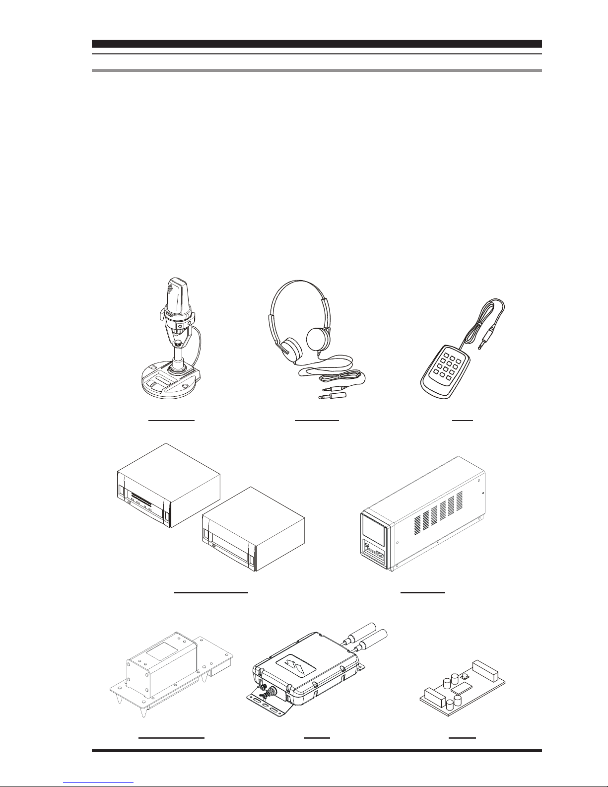
The Data Management Unit (DMU-2000) is available as
an option for the FT-950. It provides extensive display
capabilities via a user-supplied computer monitor. Included
are Band Scope, Audio Scope, X-Y Oscilloscope, World
Clock, Rotator Control, extensive Transceiver Status Dis-
plays, and Station Logging Capability.
For exceptional protection from strong signal interference,
the optional RF μTuning Kits may be connected via the
rear panel. The μTuning Kits provide extraordinarily sharp
selectivity, and protect your receiver from close-in inter-
ference on a crowded band.
In the front end, you may select one of two RF preamplifi-
ers, or IPO (Intercept Point Optimization) providing di-
rect feed to the first mixer. Three levels of RF attenuation
are available in 6-dB steps.
The FT-950 receiver utilizes DSP filtering, incorporating
many of the features of the FTDX9000, such as, Variable
Bandwidth, IF Shift, and Passband Contour tuning. Also
provided are Digital Noise Reduction, Digital Auto-Notch
Filtering and a manually tuned IF Notch filter.
On the transmit side, the Yaesu-exclusive Three-Band Para-
metric Microphone Equalizer allows precise and flexible
adjustment of the waveform created by your voice and
microphone. The Amplitude, Center Frequency, and Band-
width are adjusted separately for the low, mid-range, and
high-frequency audio spectra. The transmitted bandwidth
may also be adjusted.
Advanced features include: Direct Keyboard Frequency
Entry and Band Change, Speech Processor, IF Monitor
for Voice modes, CW Pitch control, CW Spot switch, Full
CW QSK, adjustable IF Noise Blanker, and all-mode
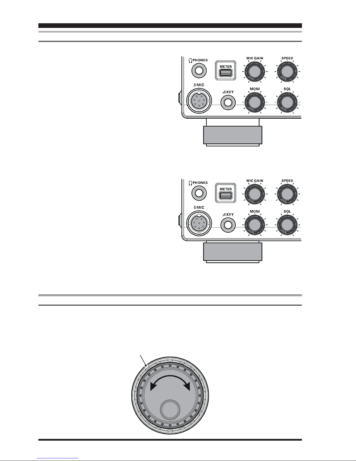
Squelch. Two TX/RX antenna ports are provided on the
rear panel. Two key jacks are provided (one on the front
and one on the rear panel). The key jacks may be config-
ured independently for paddle input, connection to a
straight key, or computer-driven keying interface. The CW
Message Memory is provided.
Frequency setup is straightforward on the FT-950. Enter
frequency directly for both VFO-A and VFO-B. Separate
keys are provided for band selection. Each band key pro-
vides three separate VFO settings for three different parts
of each band. You can establish three independent VFO
settings of frequency, mode, and filter for each band.
In addition, 99 memories are provided to store: Frequency,
Mode, IF filter selection, Clarifier offset, and Scan-skip
status. What’s more, five quick-recall (“QMB”) memo-
ries can instantly store operational settings at the push of a
button.
The built-in antenna tuner includes 100 memories that au-
tomatically store antenna matching settings for rapid au-
tomatic recall later.
Interfacing for digital modes is extremely simple with the
FT-950, thanks to the dedicated RTTY/PKT connection
jack on the rear panel. Optimization of the filter passband,
DSP settings, carrier insertion point, and display offset for
digital modes, is possible via the Menu programming sys-
tem.
Advanced technology is only part of the FT-950 story.
Vertex Standard stands behind our products with a world-
wide network of dealers and service centers. We greatly
appreciate your investment in the FT-950, and we look
forward to helping you get the most out of your new trans-
ceiver. Please feel free to contact your nearest dealer, or
one of Vertex Standard’s national headquarters offices, for
technical advice, interfacing assistance, or accessory rec-
ommendation. Watch Vertex Standard U.S.A.’s Home Page
for late-breaking information about Vertex, Standard Ho-
rizon, and Yaesu products: http://www.vertexstandard.com.
Please read this manual thoroughly, to gain maximum un-
derstanding of the full capability of the FT-950. We thank
you again for your purchase!

Page 2 FT-950 OPERATING MANUAL
TABLE OF CONTENTS
General Description ..................................................... 1
Accessories & Options ................................................. 4
Supplied Accessories ............................................... 4
Available Options ..................................................... 5
Before You Begin ......................................................... 6
Extending the Front Feet .......................................... 6
Adjusting the Main Tuning Dial Torque .................. 6
Resetting the Microprocessor .................................. 7
Resetting Memories (Only) ................................ 7
Menu Resetting................................................... 7
Full Reset ............................................................ 7
Installation and Interconnections ............................... 8
Antenna Considerations ........................................... 8
About Coaxial Cable ................................................ 8
Grounding ................................................................ 9
Connection of Antenna and Power Cables ............. 10
Connection of Microphone and Headphone .......... 11
Key, Keyer, and Computer-Driven Keying
Interconnections ..................................................... 12
VL-1000 Linear Amplifier Interconnections .......... 13
Interfacing to Other Linear Amplifiers ................... 14
Plug/Connector Pinout Diagrams ............................ 15
Front Panel Controls & Switches ............................. 16
Display Indications .................................................... 24
Rear Panel .................................................................. 27
Basic Operation: Receiving on Amateur Bands ...... 29
Operation on 60-Meter (5 MHz) Band
(U.S. version only) ................................................. 32
CLAR (Clarifier) Operation ................................... 33
LOCK ..................................................................... 34
DIMMER ............................................................... 34
Convenience Features................................................ 35
Using VFO-B ......................................................... 35
“MY Bands” Operation .......................................... 36
Band Stack Operation ............................................ 37
C.S (Custom Switch) .............................................. 37
Rotator Control Functions ...................................... 38
More Frequency Navigation Techniques ............... 39
Keyboard Frequency Entry .............................. 39
Using the [CLAR/VFO-B] knob ...................... 39
Using the UP/DOWN switches of
the supplied MH-31B8 Hand Microphone ........ 39
Interference Rejection ............................................... 40
Receiver Operation (Front End Block Diagram) ... 40
ATT ........................................................................ 41
μ-Tune Filter .......................................................... 42
IPO (Intercept Point Optimization) ........................ 44
R.FLT (Roofing Filters) ......................................... 45
IF Noise Blanker (NB) Operation .......................... 46
CONTOUR Control Operation .............................. 47
IF SHIFT Operation ............................................... 48
WIDTH (IF DSP Bandwidth) Tuning .................... 49
Using IF Shift and Width Together................... 49
NARROW (NAR) One-Touch IF Filter Selection ... 50
IF Notch Filter Operation....................................... 51
Digital Notch Filter (DNF) Operation ................... 52
Digital Noise Reduction (DNR) Operation ............ 52
RF Gain (SSB/CW/AM Modes) ............................ 53
Tools for Comfortable and Effective Reception ...... 54
Audio Pitch Control ............................................... 54
Mute Feature .......................................................... 54
AGC (Automatic Gain Control) ............................. 55
SSB/AM Mode Transmission .................................... 56
Using the Automatic Antenna Tuner ........................ 58
ATU Operation ....................................................... 58
About ATU Operation ............................................ 59
Enhancing Transmit Signal Quality ......................... 60
Parametric Microphone Equalizer ......................... 60
Using the Speech Processor ................................... 62
Adjusting the SSB Transmitted Bandwidth ........... 63
Transmitter Convenience Features .......................... 64
Voice Memory ........................................................ 64
Voice Memory Operation from
the optional FH-2 Remote Control Keypad ..... 65
VOX (Automatic TX/RX Switching using Voice Control) ............. 66
MONITOR ............................................................. 67
Split Operation Using the TX Clarifier .................. 68
Split-Frequency Operation ..................................... 69
Quick Split Operation ....................................... 69

Page 3FT-950 OPERATING MANUAL
TABLE OF CONTENTS
CW Mode Operation ................................................. 70
Setup for Straight Key
(and Straight Key emulation) Operation ................ 70
Using the Built-in Electronic Keyer ....................... 71
Full Break-in (QSK) Operation ........................ 72
Setting the Keyer Weight (Dot/Dash)Ratio ...... 72
Selecting the Keyer Operating Mode ............... 73
CW Convenience Features ........................................ 74
CW Spotting (Zero-Beating) .................................. 74
Using CW Reverse ................................................. 75
CW Delay Time Setting ......................................... 76
CW Pitch Adjustment ............................................. 76
Contest Memory Keyer .......................................... 78
Message Memory ............................................. 78
Transmitting in the Beacon Mode .............. 79
TEXT Memory ................................................. 80
Contest Number Programming ................... 82
Contest Memory Keyer
(Using the optional FH-2 Remote Control Keypad)
...... 82
Message Memory ............................................. 82
TEXT Memory ................................................. 84
FM Mode Operation ................................................. 87
Basic Operation ...................................................... 87
Repeater Operation ................................................ 88
Tone Squelch Operation ......................................... 89
Memory Operation .................................................... 90
Convenient Memory functions ............................... 90
QMB (Quick Memory Bank) ................................. 91
Standard Memory Operation .................................. 92
Memory Storage ............................................... 92
Memory Channel Recall ................................... 92
Checking Memory Channel Status ................... 93
Erasing Memory Channel Data ........................ 93
Moving Memory Data to
the Main Band (VFO-A) .................................. 94
Memory Tune Operation .................................. 94
Memory Groups ..................................................... 95
Memory Group Assignment ............................. 95
Choosing the Desired Memory Group ............. 95
Operation on Alaska Emergency Frequency:
5167.5 kHz (U.S. Version Only) ................................ 96
VFO and Memory Scanning ..................................... 97
VFO Scanning ........................................................ 97
Memory Scan ......................................................... 98
PMS (Programmable Memory Scan)....................... 99
Packet Operation ..................................................... 100
Packet Setup (Including Subcarrier Frequency) .. 100
Basic Setup .......................................................... 100
RTTY (Radio Teletype) Operation ......................... 101
Setting Up for RTTY Operation ........................... 101
Basic Setup .......................................................... 101
Miscellaneous AFSK-Based Data Modes .............. 102
About the Transverter Output Terminal ............... 107
Menu Mode .............................................................. 103
Using the Menu .................................................... 103
Menu Mode Reset ................................................ 103
AGC Group .......................................................... 108
DISPLAY Group .................................................. 108
DVS Group .......................................................... 109
KEYER Group ..................................................... 109
GENERAL Group ................................................ 110
MODE-AM Group ............................................... 111
MODE-CW Group ............................................... 111
MODE-DATA Group ........................................... 113
MODE-FM Group ............................................... 113
MODE-RTTY Group ........................................... 113
MODE-SSB Group .............................................. 114
RX GENERAL Group ......................................... 114
SCOPE Group ...................................................... 115
TUNING Group ................................................... 116
TX AUDIO Group ............................................... 116
TX GNRL Group ................................................. 118
Installation of the Optional Filter .......................... 120
Voice Memory Unit (DVS-6) ............................... 120
RF μTuning Kit .................................................... 121
FC-40 External Automatic Antenna Tuner ........... 122
Data Management Unit (DMU-2000) .................. 124
Specifications ............................................................ 126

Page 4 FT-950 OPERATING MANUAL
ACCESSORIES & OPTIONS
SUPPLIED ACCESSORIES
Hand Microphone (MH-31B8)1 pc A07890001
DC Power Cord 1 pc T9025225
Spare Fuse (25A) 1 pc Q0000074
Operating Manual 1 pc
Warranty Card 1 pc

Page 5FT-950 OPERATING MANUAL
ACCESSORIES & OPTIONS
AVAILABLE OPTIONS
MD-200A8X Ultra-High-Fidelity Desktop Microphone
MD-100A8X Desktop Microphone
YH-77STA Lightweight Stereo Headphone
VL-1000/VP-1000 Linear Amplifier/AC Power Supply
DMU-2000 Data Management Unit
RF μTuning Kit A For 160 m Band
RF μTuning Kit B For 80/40 m Bands
RF μTuning Kit C For 30/20 m Bands
FC-40 External Automatic Antenna Tuner
DVS-6 Voice Memory Unit
FH-2 Remote Control Keypad
CT-118 VL-1000 Linear Amplifire Connection Cable
CT Cable (MDIN6P - MDIN6P 2m) Antenna Rotator Connection Cable (P/N T9101556)
CT Cable (MDIN10P - Bare Wire 2m) Linear Amplifier Connection Cable (P/N T9207451)
MD-200A8X YH-77STA FH-2
DMU-2000VL-1000/VP-1000
RF μTuning Kit DVS-6FC-40

Page 6 FT-950 OPERATING MANUAL
EXTENDING THE FRONT FEET
To elevate the front panel for easy viewing, the front left and right feet of the bottom case may be extended.
Pull the front legs outward from the bottom panel.
Rotate the legs counter-clockwise to lock them in the
extended position. Be sure the legs have locked se-
curely in place, because the transceiver is quite heavy
and an unlocked leg could result in damage, should
the transceiver move suddenly.
ADJUSTING THE MAIN TUNING DIAL TORQUE
The torque (drag) of the Main Tuning Dial knob may be
adjusted according to your preferences. Simply hold down
the rear skirt of the knob, and while holding it in place
rotate the knob clockwise to reduce the drag or counter-
clockwise to increase the drag. Available adjustment range
is 120°.
Retracting the Front Feet
Rotate the legs clockwise, and push them inward while
rotating to the right.
The front feet should now be locked in the retracted
position.
BEFORE YOU BEGIN
Hold the Skirt
TIGHTEN LOOSEN

Page 7FT-950 OPERATING MANUAL
RESETTING THE MICROPROCESSOR
RESETTING MEMORIES (ONLY)
Use this procedure to reset (clear) the previously stored
Memory channels, without affecting any configuration
changes you may have made to the Menu settings.
1. Press the front panel’s [POWER]switch to turn the
transceiver off.
2. Press and hold in the [A
XX
XX
X
M]button; while holding it
in, press and hold in the front panel’s [POWER]switch
to turn the transceiver on. Once the transceiver comes
on, you may release the buttons.
MENU RESETTING
Use this procedure to restore the Menu settings to their
factory defaults, without affecting the memories you have
programmed.
1. Press the front panel [POWER]switch to turn the trans-
ceiver off.
2. Press and hold in the [MENU]button; while holding it
in, press and hold in the front panel [POWER]switch
to turn the transceiver on. Once the transceiver comes
on, you may release the buttons.
FULL RESET
Use this procedure to restore all Menu and Memory set-
tings to their original factory defaults. All Memories will
be cleared by this procedure.
1. Press the front panel [POWER]switch to turn the trans-
ceiver off.
2. Press and hold the [FAST]and [LOCK]buttons; while
holding them in, press and hold in the front panel
[POWER]switch to turn the transceiver on. Once the
transceiver comes on, you may release the buttons.
IMPORTANT NOTE:
When the optional μTuning Kit is connected to the FT-
950, disconnect all the cables from the μTuning Kit be-
fore performing the Full Reset.
[POWER]button [A
XX
XX
X
M]button
BEFORE YOU BEGIN
[LOCK]button
[FAST]button
[POWER]button [MENU]button
[POWER]button

Page 8 FT-950 OPERATING MANUAL
ANTENNA CONSIDERATIONS
The FT-950 is designed for use with any antenna system providing a 50 Ohm resistive impedance at the desired operating
frequency. While minor excursions from the 50-Ohm specification are of no consequence, if the Standing Wave Ratio
(SWR) present at the Antenna jack is greater than 3:1, the transceiver’s Automatic Antenna Tuner may not be able to reduce
the impedance mismatch to an acceptable value.
Every effort should be made to ensure that the impedance of the antenna system be as close as possible to the specified 50-
Ohm value. Note that the “G5RV” type antenna does not provide a 50-Ohm impedance on all HF Amateur bands. An
external wide-range antenna coupler must be used with this antenna type.
Any antenna to be used with the FT-950 must be fed from the transceiver with 50 Ohm coaxial cable. Therefore, when
using a “balanced” antenna such as a dipole, remember that a balun or other matching/balancing device must be used to
ensure proper antenna performance.
The same precautions apply to any additional (receive-only) antennas connected to the antenna jacks; if your receive-only
antennas do not have impedance near 50 Ohms at the operating frequency, you may need to install an external antenna tuner
to obtain optimum performance.
ABOUT COAXIAL CABLE
Use high-quality 50-Ohm coaxial cable for the lead-in to your FT-950 transceiver. All efforts at providing an efficient
antenna system will be wasted if poor quality, lossy coaxial cable is used. This transceiver utilizes standard “M” (“PL-259”)
type connectors.
INSTALLATION AND INTERCONNECTIONS
1/16''
3/4''
1 1/8''
3/4''
Adapter
1/8''
5/8''3/8''
TYPICAL PL-259 INSTALLATION

Page 9FT-950 OPERATING MANUAL
INSTALLATION AND INTERCONNECTIONS
GROUNDING
The FT-950 transceiver, like any other HF communications apparatus, requires an effective ground system for maximum
electrical safety and best communications effectiveness. A good ground system can contribute to station efficiency in a
number of ways:
It can minimize the possibility of electrical shock to the operator.
It can minimize RF currents flowing on the shield of the coaxial cable and the chassis of the transceiver; such currents
may lead to radiation, which can cause interference to home entertainment devices or laboratory test equipment.
It can minimize the possibility of erratic transceiver/accessory operation caused by RF feedback and/or improper cur-
rent flow through logic devices.
An effective earth ground system may take several forms; for a more complete discussion, see an appropriate RF engineer-
ing text. The information below is intended only as a guideline.
Typically, the ground connection consists of one or more copper-clad steel rods, driven into the ground. If multiple ground
rods are used, they should be positioned in a “V” configuration, and bonded together at the base of the “V” which is nearest
the station location. Use a heavy, braided cable (such as the discarded shield from type RG-213 coaxial cable), and strong
cable clamps to secure the braided cable(s) to the ground rods. Be sure to weatherproof the connections to ensure many
years of reliable service. Use the same type of heavy, braided cable for the connections to the station ground bus (described
below).
Inside the station, a common ground bus consisting of a copper pipe of at least 25 mm (1”) diameter should be used. An
alternative station ground bus may consist of a wide copper plate (single-sided circuit board material is ideal) secured to the
bottom of the operating desk. Grounding connections from individual transceivers, power supplies, and data communica-
tions devices (TNCs, etc.) should be made directly to the ground bus using a heavy, braided cable.
Do not “Daisy-Chain” ground connections from one electrical device to another, and thence to the ground bus. This method
may nullify any attempt at effective radio frequency grounding. See the drawing below for examples of proper grounding
techniques.
Inspect the ground system - inside the station as well as outside - on a regular basis to ensure continued performance and
safety.
Besides following the above guidelines carefully, note that household or industrial gas lines must never be used in an
attempt to establish an electrical ground. Cold water pipes may, in some instances, help in the grounding effort, but gas lines
represent a significant explosion hazard, and must never be used.
PROPER GROUND CONNECTION
Linear
Amplifier
TNC
Transceiver
"Daisy Chain"
Linear
Amplifier
TNC
Transceiver
IMPROPER GROUND CONNECTION

Page 10 FT-950 OPERATING MANUAL
TO
1ANT DC IN
2
FROM
GND ROT LINEAR TUNER PTT REC REM KEY
DMU CAT
EXT
SPKR
-TUNE -TUNE
INPUT 22 A
: DC 13.8 V
ANTENNA“2”
ANTENNA“1”
VA
005510 2015 3020 40
CONTINUOUS CURRENT 25A
OVERLOAD
POWER
ON
OFF
RED BLACK
FUSE: 25A
CONNECTION OF ANTENNA AND POWER CABLES
Please follow the outline in the illustration regarding the proper connection of antenna coaxial cables, as well as the DC
power cable. The DC power connector for the FT-950 must only be connected to a DC source providing 13.8 Volts DC
(±10 %), and capable of at least 22 Amperes of current. Always observe proper polarity when making DC connection:
The RED DC power lead connects to the Positive (+) DC terminal.
The BLACK DC power lead connects to the Negative (–) DC terminal.
We recommend the use of the FP-1030A AC Power Supply. Other models of power supplies may be used with the FT-950,
but the 13.8 VDC input voltage, 22-Ampere current capability, and DC cable polarity guidelines described above must be
strictly followed.
Note that other manufacturers may use the same type of DC power connections as does your FT-950 transceiver, however,
the wiring configuration may be different from that specified for your transceiver. Serious damage can be caused if im-
proper DC connections are made; consult with a qualified service technician when in doubt.
Permanent damage can result when improper supply voltage, or reverse-polarity voltage, is applied to the FT-950.
The Limited Warranty on this transceiver does not cover damage caused by application of AC voltage, reverse
polarity DC, or DC voltage outside the specified range of 13.8 V ±10 %. When replacing fuses, be certain to use a fuse of
the proper rating. The FT-950 requires a 25 A blade fuse.
ADVICE:
Do not position the FT-950 in a location with direct exposure to sunshine.
Do not position the FT-950 in a location exposed to dust and/or high humidity.
Ensure adequate ventilation around the FT-950, to prevent heat build-up and possible reduction of performance due to
high heat.
Do not install the FT-950 on an unstable desk or table. Do not place in a location where objects may fall onto it from above.
To minimize the possibility of interference to home entertainment devices, take all precautionary steps including sepa-
ration of TV/FM antennas from Amateur transmitting antennas to the greatest extent possible, and keep transmitting
coaxial cables separated from cables connected to home entertainment devices.
Ensure that the DC power cord is not subject to undue stress or bending, which could damage the cable or cause it to be
accidentally unplugged from the rear panel DC IN jack.
Be certain to install your transmitting antenna(s) so they cannot possibly come in contact with TV/FM radio or other
antennas, or with power or telephone lines.
Use a short, thick, braided
cable to connect your sta-
tion equipment to the bur-
ied ground rod (or alterna-
tive earth ground system).
INSTALLATION AND INTERCONNECTIONS

Page 11FT-950 OPERATING MANUAL
CONNECTION OF MICROPHONE AND HEADPHONE
INSTALLATION AND INTERCONNECTIONS

Page 12 FT-950 OPERATING MANUAL
KEY, KEYER, AND COMPUTER-DRIVEN KEYING INTERCONNECTIONS
The FT-950 includes many features for the CW operator. These functions will be detailed in the “Operation” section later.
Besides the built-in Electronic Keyer, two key jacks are provided, one on the front and one on the rear panel, for convenient
connection to keying devices.
The Menu selections allow you to configure the front and rear panel KEY jacks according to the device you wish to
connect. For example, you may connect your keyer paddle to the front panel KEY jack, and use Menu item “037 A1A F-037 A1A F-
037 A1A F-037 A1A F-
037 A1A F-
TYPETYPE
TYPETYPE
TYPE” for paddle input, and also connect the keying line from your personal computer (which emulates a “straight key”),
to the rear panel KEY jack, and configure the rear panel jack using Menu item “039 A1A R-TYPE039 A1A R-TYPE
039 A1A R-TYPE039 A1A R-TYPE
039 A1A R-TYPE”.
Both KEY jacks on the FT-950 utilize “Positive” keying voltage. Key-up voltage is approximately +3.3V DC, and key-
down current is approximately 0.3 mA. When connecting a key or other device to the KEY jacks, use only a 3-contact
(“stereo”) 1/4” phone plug; a 2-contact plug will place a short between the ring and (grounded) shaft of the plug, resulting
in a constant “key-down” condition in some circumstances.
INSTALLATION AND INTERCONNECTIONS
KEY
DMU CAT
-TUNE

Page 13FT-950 OPERATING MANUAL
TO
1ANT DC IN
2
FROM
GND ROT LINEAR TUNER PTT REC REM K EY
DMU CAT
EXT
SPKR
INPUT: DC 13.8 V
22 A
-TUN E -TUNE
ANT 1
ANT 2
ANT 3
ANT 4
REMOTE
ON
OFF
BAND DATA 1
BAND DATA 2
GND
ALC 2
ALC 1
PTT 2
PTT 1 INPUT 1
INPUT 2
CONTROL
DC48V IN
ANT1
ANT2
INPUT
ANT1
ANT2
ANT3
INPUT2
LINEAR
BAND-DATA2
GND
GND
DC48VIN
CONTROL
ALC2
VP-1000
¾
VP-1000
¾
DC 13.8 V
HF Antenna
50MHz Antenna
CT-118 Connection Cable (Option)
Antenna Cable (Not Supplied)
VL-1000 LINEAR AMPLIFIER INTERCONNECTIONS
Be sure that both the FT-950 and VL-1000 are turned off, then follow the installation recommendations contained in the
illustration.
NOTE:
Please refer to the VL-1000 Operating Manual for details regarding amplifier operation.
Please do not attempt to connect or disconnect coaxial cables when your hands are wet.
INSTALLATION AND INTERCONNECTIONS
To link the FT-950 and VL-1000 Power
switches, set the VL-1000 REMOTE switch
to the “ON” position.
Set the front panel’s
INPUT switch to the
“INPUT2”.

Page 14 FT-950 OPERATING MANUAL
INSTALLATION AND INTERCONNECTIONS
INTERFACING TO OTHER LINEAR AMPLIFIERS
NOTE
The TX GND OUT pin (pin 2) of the LINEAR jack is
a transistor “open collector” circuit. It is capable of
handling positive relay coil voltages up to +60VDC at
200 mA or +30 VDC at 1 A. If you plan to use multiple
linear amplifiers for different bands, you must provide
external band switching of the “Linear Tx” relay con-
trol line from the “TX GND OUT” line at the LIN-
EAR jack.
The specified range for ALC voltage to be used with
the FT-950 is 0 to -4 Volts DC.
Amplifier systems utilizing different ALC voltages will
not work correctly with the FT-950, and their ALC
lines must not be connected if this is the case.
IMPORTANT NOTE!
Do not exceed the maximum voltage or current ratings
for the “TX GND OUT” pin (pin 2) of the LINEAR
jack. This line is not compatible with negative DC volt-
ages, or AC voltages of any magnitude.
Most amplifier control relay systems require only low
DC voltage/current switching capability (typically,
+12V DC at 25 ~ 75 mA), and the switching transistor
in the FT-950 will easily accommodate such amplifi-
ers.
Wire Color
Orange
Yellow
Green
Red
White
Blue
Violet
Brown
Black
Gray
Light Blue
LINEA Jack (Pin Number)
1
2
3
4
5
6
7
8
9
10
Case
Function
+13.8 V
TX GND
GND
BAND DATA A
BAND DATA B
BAND DATA C
BAND DATA D
TX INH
EXT ALC IN
TX REQ IN
Shield
Linear Amplifier Connection Cable (T9207451)
Color Code Information
TO
1ANT DC IN
2
FROM
GND ROT LINEAR TUNER PTT REC REM KEY
DMU CAT
EXT
SPKR
INPUT: DC 13.8 V
22 A
-TUN E -TUN E
EERYALC
ACFUSEGND
RF INRF OUT
ANT1
ANT2
ANT
HFAntenna
50MHzAntenna
INPUT
GND
GND
INPUT
DC13.8V
Antenna Cable (Not Supplied)
LINEAR
Light-Blue
Linear Amplifier Connection Cable (T9207451: Option)
Black
Green
Yellow
Note
When the FC-40 is connected to the FT-950, TX
GND (pin 2) of the TUNER jack and the LINEAR
jack (pin 2) are common circuits.
Therefore, the maximum voltage at TX GND (pin
2) of the LINEAR jack must not exceed +5V.

Page 15FT-950 OPERATING MANUAL
PLUG /CONNECTOR PINOUT DIAGRAMS
IMPORTANT NOTE:
The μ-TUNE and DMU connectors are special connectors for this trans-
ceiver. Please do not connect any accessory or other device not specifically
approved by Vertex Standard. Failure to observe this precaution may cause
damage not covered by the Limited Warranty on this apparatus.
Do not use
2-conductor type plug
RTTY/PKTLINEAR
RCA PLUG
KEY
MIC CAT
SIGNAL or ()
+
GND or (-- )-
EXT SPKR
DC IN
TUNER
ROT ROTATOR
()
PHONE
REM REMOTE
()
(as viewed from front panel)
(as viewed from rear panel)
DOT DASH COMMON
For Internal Keyer
KEY GND
For Straight Key
(as viewed from rear panel)
CW ROTATION
SPEED
DIRECTION
GND
NC
CCW ROTATION
SIGNAL (RIGHT)
SIGNAL (LEFT) GND
GND
SIGNAL
GND
SIGNAL
+13V OUT
TX GND
GND
BAND DATA A
BAND DATA B
BAND DATA C
BAND DATA D
TX INH
EXT ALC IN
TX REQ IN
N/A
SERIAL OUT
SERIAL IN
N/A
GND
N/A
RTS
CTS
NC
UP
+5V
DOWN
FAST
GND
PTT
MIC GND
MIC
DATA IN
GND
DATA PTT
FSK IN
DATA OUT
SQL OUT
+13V OUT
TX GND
GND
RX D
TX D
TUNER SENSE
RESET OUT
TX INH

Page 16 FT-950 OPERATING MANUAL
[POWER]Switch
Press and hold in this switch for two seconds to turn
the transceiver on. Similarly, press and hold in this
switch for two seconds to turn the transceiver off.
[ANT 1-2]Switch
Pressing this switch selects the ANT 1 or the ANT 2
connector on the rear panel, and allows convenient an-
tenna switching at the press of button. The selected
antenna jack is indicated on the Block Diagram Dis-
play shown in the Transceiver Display.
[TUNE]Switch
This is the on/off switch for the FT-950’s Automatic
Antenna Tuner.
Pressing this button momentarily places the antenna
tuner in line between the transmitter final amplifier and
the antenna jack (The “ ” icon will appear in
the display). Reception is not affected.
Pressing and holding in this button for two seconds,
while receiving in an amateur band, activates the trans-
mitter for a few seconds while the automatic antenna
tuner rematches the antenna system impedance for
minimum SWR. The resulting setting is automatically
stored in one of the antenna tuner’s 100 memories, for
instant automatic recall later when the receiver is tuned
near the same frequency.
Pressing this button momentarily, while the Tuner is
engaged, will take the Automatic Antenna tuner out of
the transmit line.
NOTE:
When the Automatic Antenna Tuner is tuning itself, a
signal is being transmitted. Therefore, be certain that
an antenna or dummy load is connected to the selected
antenna jack before pressing and holding in the [TUNE]
button to start antenna tuning.
FRONT PANEL CONTROLS & SWITCHES

Page 17FT-950 OPERATING MANUAL
[MOX]Switch
Pressing this button engages the PTT (Push to Talk)
circuit, to activate the transmitter (the LED inside this
button will glow red). It must be turned off (the red
LED will be off) for reception. This button replicates
the action of the Push to Talk (PTT) switch on the mi-
crophone. When engaging the [MOX]button, or oth-
erwise causing a transmission to be started, be certain
you have either an antenna or 50-Ohm dummy load
connected to the selected Antenna jack.
[VOX]Switch
This button enables automatic voice-actuated transmit-
ter switching in the SSB, AM, and FM modes. While
activated, the LED inside this button glows red. The
controls affecting VOX operation are the Menu items
“114 TGEN V GAIN114 TGEN V GAIN
114 TGEN V GAIN114 TGEN V GAIN
114 TGEN V GAIN”, “115 TGEN VOX DLY115 TGEN VOX DLY
115 TGEN VOX DLY115 TGEN VOX DLY
115 TGEN VOX DLY”, and
“116 TGEN ANTI VOX116 TGEN ANTI VOX
116 TGEN ANTI VOX116 TGEN ANTI VOX
116 TGEN ANTI VOX”. By proper adjustment of these
controls, hands-free voice-actuated operation is pos-
sible.
[MONI](Monitor)Switch
This button enables the transmit monitor in SSB, CW,
AM, and FM modes. While activated, the “ ” icon
appears in the display. The Monitor audio level may
be adjusted by turning the [MONI]knob.
ADVICE:
When using headphones, the Monitor function is very
helpful while adjusting the Parametric Equalizer or
other voice quality adjustments. The voice heard in the
headphones represents the transmitted audio qualities.
[PROC](Processor) Switch
This button enables the Parametric Microphone Equal-
izer and Speech Processor for SSB/AM transmission.
When the Parametric Microphone Equalizer is acti-
vated, the “ ” icon appears in the display. When
the Speech Processor is activated, the “ ” and
“” icons appear in the display. Adjustment of
the Processor level is accomplished via the Menu item
“109 TGEN PROCLVL109 TGEN PROCLVL
109 TGEN PROCLVL109 TGEN PROCLVL
109 TGEN PROCLVL”.
ADVICE:
The Speech Processor is a tool for increasing the
average power output through a compression tech-
nique. However, if the Processor level is advanced
too far, the increase in compression becomes
counter-productive, as intelligibility will suffer. We
recommend that you monitor the sound of your sig-
nal using the Monitor (with headphones).
When the optional Data Management Unit (DMU-
2000) is connected, you may use the Audio Scope/
Oscilloscope page to help you adjust the setting of
the compression level of the Speech Processor for
optimum performance using your voice and micro-
phone.
[SPOT]Switch
This button turns on the CW receiver spotting tone; by
matching the SPOT tone to that of the incoming CW
signal (precisely the same pitch), you will be “zero
beating” your transmitted signal on to the frequency of
the other station.
The offset tone frequency will be indicated in the fre-
quency display area of the display while this button is
pressed.
[BK-IN]Switch
This button turns the CW break-in capability on and
off. While CW break-in is activated, the “ ” icon
appears in the display.
[KEYER]Switch
This button toggles the internal CW keyer on and off.
While activated, the “ ” icon appears in the dis-
play. The Keyer sending speed is adjusted via the front
panel’s [SPEED]knob and the CW Hang Time is ad-
justed via the Menu item “044 A1A DELAY044 A1A DELAY
044 A1A DELAY044 A1A DELAY
044 A1A DELAY”.
[AGC]Switch
This button selects the AGC characteristics for the re-
ceiver. Available selections are FAST, MID, SLOW,
or AUTO. The “AGC” icon will change according to
the AGC characteristics selected.
Press the [AGC]button repeatedly to select the de-
sired receiver-recovery time constant. Press and hold
in the [AGC]button for two seconds to disable the
AGC (for testing or weak-signal reception).
ADVICE:
The Attenuator may be used in conjunction with
the [IPO]button to provide two stages of signal
reduction when an extremely strong signal is being
received.
If the AGC receiver-recovery time is set to “Off”
by pressing and holding in the [AGC]button, the
S-meter will no longer deflect. Additionally, you
will likely encounter distortion on stronger signals,
as the IF amplifiers and the following stages are
probably being overloaded.
FRONT PANEL CONTROLS & SWITCHES

Page 18 FT-950 OPERATING MANUAL
FRONT PANEL CONTROLS & SWITCHES
PHONES Jack
A 1/4-inch, 3-contact jack accepts either monaural or
stereo headphones with 2- or 3-contact plugs. When a
plug is inserted, the loudspeaker is disabled.
NOTE:
When wearing headphones, we recommend that you
turn the AF Gain levels down to their lowest settings
before turning power on, to minimize the impact on
your hearing caused by audio “pops” during switch-
on.
[METER]Switch
This button determines the function of the meter dur-
ing transmission.
Press this button to change the meter function in the
transmit mode as follows:
ALCALC
ALCALC
ALC ÆÆ
ÆÆ
ÆSWRSWR
SWRSWR
SWR ÆÆ
ÆÆ
ÆIDID
IDID
ID ÆÆ
ÆÆ
ÆVDDVDD
VDDVDD
VDD ÆÆ
ÆÆ
ÆCOMPCOMP
COMPCOMP
COMP ÆÆ
ÆÆ
ÆALCALC
ALCALC
ALC ……
ALCALC
ALCALC
ALC: Indicates the relative ALC voltage.
SWRSWR
SWRSWR
SWR: Indicates the Standing Wave Ratio (Forward/
Reflected).
IDID
IDID
ID: Indicates the final amplifier drain current.
VDDVDD
VDDVDD
VDD: Indicates the final amplifier drain voltage.
COMPCOMP
COMPCOMP
COMP: Indicates the speech compressor level (SSB
modes only).
[MIC GAIN]Knob
This knob adjusts the microphone input level for (non-
processed) SSB and AM transmission.
ADVICE:
Adjust the [MIC GAIN]knob while speaking in a some-
what louder than normal voice level, watch the ALC
level and adjust the [MIC GAIN]knob so that the ALC
level indication just reaches the right edge of the ALC
scale. Then, when you speak in your normal voice level,
you will not be over-driving the microphone amplifier
stages.
[SPEED]Knob
This knob adjusts the keying speed of the internal CW
keyer (4 ~ 60 WPM). Clockwise rotation increases the
sending speed.
When turning this knob while pressing the [KEYER]
button, the frequency display shows the keying speed.
Microphone Connector
This 8-pin jack accepts input from a microphone uti-
lizing a traditional YAESU HF transceiver pinout.
Other manuals for FT-950
9
Table of contents
Other Yaesu Transceiver manuals

Yaesu
Yaesu FTM-200DR User manual

Yaesu
Yaesu FTDX101D User manual

Yaesu
Yaesu FTdx5000 Series User manual

Yaesu
Yaesu FT-223 Instruction Manual

Yaesu
Yaesu FTdx3000 Series Manual

Yaesu
Yaesu FT-711RH Manual

Yaesu
Yaesu FT-950 Technical manual

Yaesu
Yaesu Mark-V FT-1000MP User manual

Yaesu
Yaesu FT-4XR User manual

Yaesu
Yaesu FT-767GX User manual

Yaesu
Yaesu Mark-V FT-1000MP Installation guide

Yaesu
Yaesu FT-101B User manual

Yaesu
Yaesu FT-980 User manual

Yaesu
Yaesu FT-736R Manual

Yaesu
Yaesu FT-747GX User manual

Yaesu
Yaesu FTDX5000D HF - PRODUCT REVIEW 12-2010 User manual

Yaesu
Yaesu HX290 User manual

Yaesu
Yaesu FTDX-9000D User manual

Yaesu
Yaesu FT-2900R User manual

Yaesu
Yaesu FT-990 User manual