Midea UR-JC80GE-DQ User manual

Service Manual_2018-V2.0
1
Service Manual
Wine Cooler SERIES
Applicable Models
Model Code
Applicable Models
HS-104WEN
UR-JC80GE-DQ
22033010001481
The picture in this service manual is only for reference, and specific appearance
and configuration are subject to the real product.
This manual mainly teaches the method, the specific work skill needs engineer to
accumulate through the daily work.

Service Manual_2018-V2.0
2
WARNING
Important Safety Notice
There are special components used in this equipment which are important for safety. These parts are marked
by in the Schematic Diagrams, Circuit Board Diagrams, Exploded Views and Replacement Parts List. It is
essential that these critical parts should be replaced with manufacturer’s specified parts to prevent shock, fire
or other hazards. Do not modify the original design without permission of manufacturer.
WARNING
Important Safety Notice
The Maintenance Manual is only for the use of maintenance personnel with certain experience and
background in electrical, electronic and mechanical field.
Any attempt to repair main devices may lead to personal injury and property loss.
Manufacturers or distributors are not responsible for the content of the Manual and interpretation thereof.
Midea Refrigerators
Technical Maintenance Manual
Copyright @2017
All rights reserved. Replication of all or part of the Manual in any forms shall not be allowed without written
approval by the Overseas Sales Corporation of Midea Refrigerators.

Service Manual_2018-V2.0
3
Contents
1. SIGNIFICANT UPDATE NOTES (NONE).........................................................................................................5
2. SAFETY WARNING CODE....................................................................................................................................6
2.1WARNING FOR OPERATION SAFETY ........................................................................................................................... 6
2.2 SAFETY INSTRUCTION FOR REFRIGERANT................................................................................................................. 8
3. TRANSPORT ..........................................................................................................................................................9
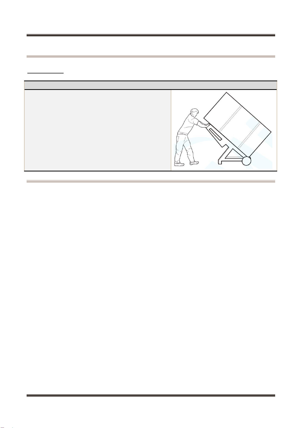
3.1 HANDLING................................................................................................................................................................... 9
4. INSTALLATION AND COMMISSIONING...........................................................................................................10
4.1 DOOR DISASSEMBLY AND ASSEMBLY ...................................................................................................................... 10
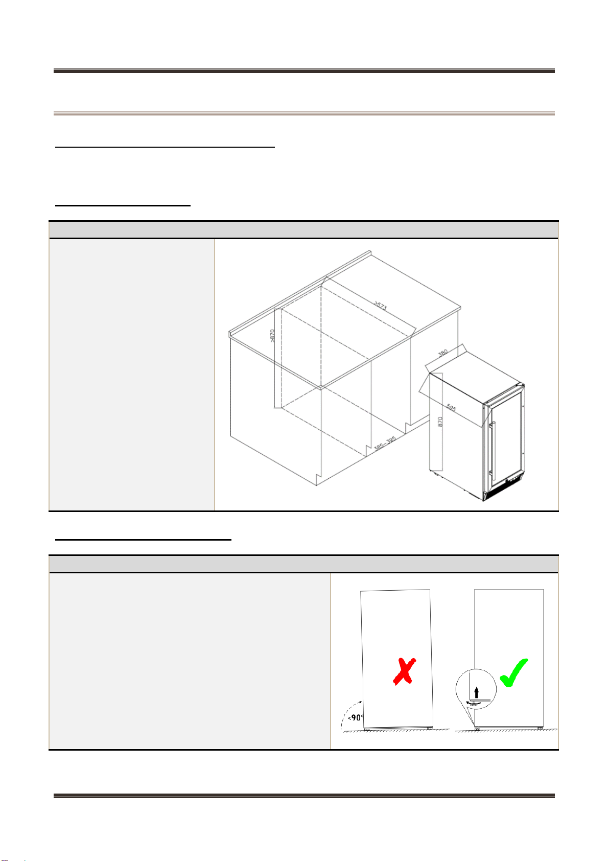
4.2 INSTALLATION LOCATION .......................................................................................................................................... 10
4.3 LEVELING OF THE REFRIGERATOR ........................................................................................................................... 10
4.4 LEFT OR RIGHT OPEN DOOR REVERSAL................................................................................................................... 11
4.5 INSTALLATION OF HANDLE........................................................................................................................................ 13
4.6 INSTALLATION OF DOOR LOCK(NONE)................................................................................................................ 13
5. PRODUCT CONFIGURATION AND DIMENSION.............................................................................................14
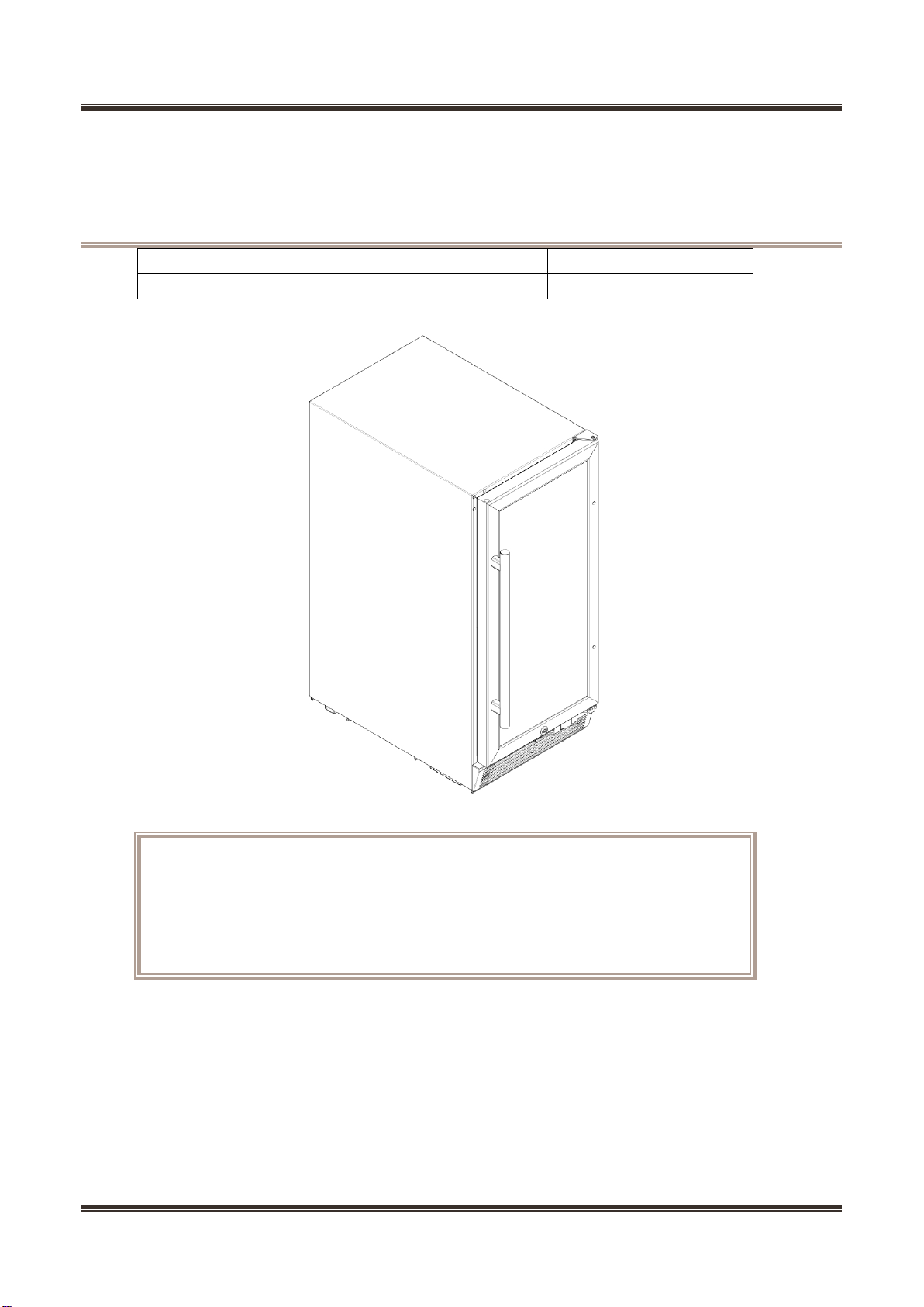
5.1 MAIN PARTS AND THEIR NAMES................................................................................................................................ 14
5.2 EXTERNAL DIMENSION.............................................................................................................................................. 15
5.3 LOCATION OF S/N.................................................................................................................................................... 16
6. PRODUCT SPECIFICATION...............................................................................................................................17
6.1 ELECTRICAL PARAMETERS....................................................................................................................................... 17
6.2 COOLING TEMPERATURE SETTING RANGE............................................................................................................... 17
6.3 CIRCUIT DIAGRAM .................................................................................................................................................... 18
7. REFRIGERATING PIPING SYSTEM AND CIRCULATING ROUTE OF COOLING AIR................................19
7.1 REFRIGERATING PIPING SYSTEM.............................................................................................................................. 19
7.2CIRCULATING ROUTE OF COOLING AIR..................................................................................................................... 19
8. DISMANTLING OF PARTS..................................................................................................................................20
8.1 PARTS ON THE DOOR................................................................................................................................................ 20
8.2 PARTS INSIDE THE REFRIGERATOR .......................................................................................................................... 20
8.3 LIGHT SYSTEM.......................................................................................................................................................... 22
8.4 COMPRESSOR CASE................................................................................................................................................. 23
8.5 DISPLAY CONTROL BOARD ....................................................................................................................................... 28
8.6 MAIN CONTROL BOARD ............................................................................................................................................ 29
9. TEMPERATURE SENSING SYSTEM.................................................................................................................31
9.1 POSITION OF SENSORS............................................................................................................................................ 31
9.2 REPLACEMENT OF SENSORS ................................................................................................................................... 31
9.3 SENSOR REPLACEMENT........................................................................................................................................... 32

Service Manual_2018-V2.0
4
10. FUNCTION AND OPERATION..........................................................................................................................34
10.1 OPERATION PANEL................................................................................................................................................. 34
10.2 TEMPERATURE CONTROL....................................................................................................................................... 34
10.3 FAULT CODE AND SOLUTIONS................................................................................................................................. 35
10.4 DEFROSTING FUNCTION......................................................................................................................................... 36
10.5 BACKUP DATA FOR POWER FAIL (NONE) .............................................................................................................. 36
11. COMPRESSOR...................................................................................................................................................37
11.1 COMPRESSOR ON AND OFF CONTROL SPECIFICATIONS........................................................................................ 37
12. TROUBLESHOOTING METHOD......................................................................................................................38
12.1 NOT COOLING......................................................................................................................................................... 38
12.2 NO WORKING OF COMPRESSOR............................................................................................................................. 39
12.3 THERMOSTAT MALFUNCTION-UNDERCOOLING...................................................................................................... 39
12.4 INSIDE FROSTING,NO DEFROSTING....................................................................................................................... 40
12.5 INSIDE FROSTING,NO DEFROSTING-MAINTENANCE GUIDELINES.......................................................................... 40
12.6 LIGHT IS NOT ON..................................................................................................................................................... 41
12.7 NOISE..................................................................................................................................................................... 42
13. FIGURES AND DETAILS OF REPAIR PARTS................................................................................................43

Service Manual_2018-V2.0
5
1. Significant update notes (None)

Service Manual_2018-V2.0
6
2. Safety Warning Code
2.1 Warning for operation safety
Important Safety Instructions
CAUTION
RISK OF ELECTRIC SHOCK
DO NOT OPEN
This symbol indicates that dangerous voltage
constituting a risk of electric shock is present
within your freezer.
This symbol indicates that there are important
operating and maintenance instructions in the
literature accompanying your freezer.
WARNING
1) Read these instructions.
2) Keep these instructions.
3) Heed all warnings.
4) Follow all instructions.
5) Do not use this appliance near water.
6) Clean only with a damp cloth.
7) Do not block any ventilation openings.
8) Install in accordance with the manufacturer’s instructions.
9) Do not install near any heat sources, such as radiators, heat registers, stoves, or
other apparatus that produce heat.
10) Do not defeat the safety purpose of the polarized or grounding-type plug.A
polarized plug has two blades with one wider than the other. A grounding type plug has two
blades and a third grounding prong. The wide blade or the third prong are provided for your
safety. If the provided plug does not fit into your outlet, consult an electrician for replacement
of the obsolete outlet.
11) Protect the power cord from being walked on or pinched, particularly at plugs,
convenience receptacles, and the point where they exit from the appliance.
12) Do not attempt to modify or extend the power cord of this appliance.
13) Unplug this appliance during lightning storms or when it will not be used for long
periods of time.
14) Make sure that the available AC power matches the voltage requirements of this
appliance.

Service Manual_2018-V2.0
7
CONNECTING ELECTRICITY
Electrical Shock Hazard.
Plug into a grounded 3-prong outlet.
Do not remove the ground prong.
Do not use an adapter.
Failure to follow these instructions can
result in death, fire, or electrical shock.
WARNING
Electric Shock Hazard
Failure to follow these instructions can result in electric shock, fire, or
death.
1) WARNING–Keep ventilation openings, in both the freezer and the built-in structure,
clear of obstruction.
2) WARNING–Do not touch the interior of the freezer with wet hands. This could result
in frost bite.
3) WARNING–Do not use mechanical devices or other means to accelerate the
defrosting process, other than those recommended by the manufacturer.
4) WARNING–Do not damage the refrigerant circuit.
5) WARNING–Do not damage the refrigerant tubing when handling, moving, or using
the freezer.
6) WARNING–DANGER–Never allow children to play with, operate, or crawl inside the
freezer. Risk of child entrapment. Before you throw away your old freezer:
6-1) Take off the doors
6-2) Leave the shelves in place so that children may not easily climb inside
7) Unplug the freezer before carrying out user maintenance on it.
8) This freezer can be used by children age eight years and older and persons with
reduced physical or mental capabilities or lack of experience and knowledge if they are
given supervision or instruction concerning the use of the freezer in a safe way and
understand the hazards involved. Children should not play with the freezer. Cleaning and
maintenance should not be performed by children without supervision.
9) If a component part is damaged, it must be replaced by the manufacturer, its service
agent, or similar qualified persons in order to avoid a hazard.
10) Please dispose of the freezer according to local regulations as the freezer contains
flammable gas and refrigerant.
11) Follow local regulations regarding disposal of the freezer due to flammable
refrigerant and gas. All refrigeration products contain refrigerants, which under the
guidelines of federal law must be removed before disposal. It is the consumer's responsibility
to comply with federal and local regulations when disposing of this product.
12) This freezer is intended to be used in household and similar environments.

Service Manual_2018-V2.0
8
13) Do not store or use gasoline or any flammable liquids inside or in the vicinity of this
freezer.
14) Do not use extension cords or ungrounded (two-prong) adapters with this freezer. If
the power cord is too short, have a qualified electrician install an outlet near the freezer. Use
of an extension cord can negatively affect the freezer’s performance.
Grounding requirement
This freezer must be grounded. This freezer is equipped with a cord having a grounding
wire with a grounding plug. The plug must be inserted into an outlet that is properly installed
and grounded.
Improper use of the grounding plug can result in a risk of electric shock. Consult a
qualified electrician or service person if the grounding instructions are not completely
understood, or if doubt exists as to whether the freezer is properly grounded.
2.2 Safety instruction for refrigerant
Explosion Hazard.
Keep flammable materials and vapors, such as gasoline, away from freezer. Failure to do so
can result in fire, explosion, or death.
Safety instruction for refrigerant
DANGER–Risk of Fire or Explosion. Flammable Refrigerant Used. To Be Repaired Only By
Trained Service Personnel. Do Not Use Mechanical Devices. Do Not Puncture Refrigerant
Tubing. CAUTION–Risk of Fire or Explosion. Flammable Refrigerant Used. Consult Repair
Manual/Owner’s Guide Before Attempting To Service This Product. All Safety Precautions
Must be Followed. CAUTION–Risk of Fire or Explosion. Dispose of Properly InAccordance
With Federal Or Local Regulations. Flammable Refrigerant Used. CAUTION–Risk of Fire or
Explosion Due To Puncture Of Refrigerant Tubing; Follow Handling Instructions Carefully.
Flammable Refrigerant Used.

Service Manual_2018-V2.0
9
3. Transport
3.1 Handling
Handling
1)Protect the refrigerator in moving it,Same as shown as lef
t photo, please move it by handcart with cushion
2)Remove all packing materials and bottom cushion, the m
ove into house for placement
3)After moving it to appropriate location, wait for 2 hours bef
ore power on.

Service Manual_2018-V2.0
10
4. Installation and commissioning
4.1 Door Disassembly and Assembly
The refrigerator door needs to be dismantled, if it cannot enter the room in the whole.
4.2 Installation location
Installation location
Location that is easy for
ventilation shall be chosen to
facilitate heat dissipation,
enhance its performance and
reduce the energy consumption.
4.3 Leveling of the refrigerator
Leveling of the refrigerator
If the refrigerator cannot be placed steadily, adjust the
footing to level it.

Service Manual_2018-V2.0
11
4.4 Left or right open door reversal
Door reversal (Vertical handle)
2)Dismantle the upper right hinge screw①,and
remove the door body;
2)Remove the 3 screws ②of the upper right
hinge, and the upper right hinge ③, remove the 3
plastic caps ④on the left, remove the 2 left and
right screws of the air outlet mask ⑤, inserts ⑥
and the air outlet mask ⑦, remove the 3 screws
of the lower hinge ⑧, lower hinge ⑨and lower
hinge axis ⑩.
3)Take out the upper left hinge ⑾from the
accessory bag of the wine cabinet, fix it on the
upper left corner of the box with screws ②, and
install the plastic cap ④removed in step 2 on the
upper right corner, and install the lower hinge
shaft ⑩on the left hole of the lower hinge ⑨,
Hinge ⑨is installed to the lower left corner of the
box with screws ⑧, the air outlet mask insert ⑥
is installed on the right side notch of the air outlet
mask ⑦, and the door mask ⑦is installed to the
lower part of the box with screws ⑤.

Service Manual_2018-V2.0
12
4)Use a wrench to remove the vertical handle ⑿,
remove the upper door shaft sleeve ⒀and the
shaft hole cap ⒁, remove the handle fixing shaft
⒂, remove the handle fixing shaft hole cap, the
positions are interchanged; remove the door limit
⒄, screw ⒅And the lower shaft sleeve ⒆is
installed on the lower left of the door; the handle
⑿is installed on the left side of the door.

Service Manual_2018-V2.0
13
5)Install the door, and fix the upper hinge shaft
①.Thus, the whole door is replaced. Collected
unused right upper hinge③.
4.5 Installation of handle
Installation of handle
1)Put the handle on glass door through the bolts.
2)Use allen wrench to fix the handle bolts,make
sure the screw hole is downward.
4.6 Installation of door lock(None)

Service Manual_2018-V2.0
14
5. Product configuration and dimension
5.1 Main parts and their names
(The picture is only for reference, and specific appearance and configuration are subject to the real
product)
Freezer chamber
Refrigerator chamber
None
1. Display control panel
2.Wooden wine shelf
3. Splitter plate
4.Outlet mask
5.Glass door

Service Manual_2018-V2.0
15
5.2 External dimension
Description
Code
HS-104WEN
Size (mm)
Height to Top of Case
A
870
Width
B
380
Depth w/Cabinet
C
545
Depth w/Door
D
615
Depth w/Handle
E
660
Depth (Door open 90 deg. w)
F
970
Depth (Door open 135 deg. w)
G
875
Width (Door open 135 deg. w)
H
665
(The picture is only for reference)

Service Manual_2018-V2.0
16
5.3 Location of S/N
Some products also have S/N on the lower part of the right side of the Cabinet.

Service Manual_2018-V2.0
17
6. Product specification
6.1 Electrical parameters
Applicable Models
HS-104WEN
Product Name
UR-JC80GE-DQ
Item
Specification
Refrigerant
R600a
Compressor
FZ35C1M-U
Starter(PTC)
QP2-4R7
Overload protector(OLP)
DRB18T61A1
Integrate PTC+OLP
None
Capacitor
None
Power filter
None
Winding resistance of compressor wiring
terminal
Rmc:13.7±7%Ω
Rsc:13.0±7%Ω
Rms=Rmc+Rsc
Winding resistance picture
The input power of compressor
52.4W
Lights inside the refrigerator
Lights inside the refrigerating chamber
LED DC12V/2W×2
Lights others
None
Switch of the refrigerator door
Pillar switch
6.2 Cooling temperature setting range
Compartment
The highest (oC)
Lowest (oC)
Refrigerating up room
14
5
Refrigerating down room
18
10

Service Manual_2018-V2.0
18
6.3 Circuit diagram

Service Manual_2018-V2.0
19
7. Refrigerating piping system and circulating route of cooling air
7.1 Refrigerating piping system
❶Compressor→❷Parallel flow condenser→❸Auxiliary condenser→❹Dry filter→❺Capillary
tube→❻Evaporator→❶Compressor
7.2 Circulating route of cooling air

Service Manual_2018-V2.0
20
8. Dismantling of parts
8.1 Parts on the door
Door seal
Door seal is installed into door liner groove.
1) Open the wine door;
2) Take the door seal ①out of door liner;
Door stopper
1)The door lamp switch stopper is installed in the lower
part of the door. Take down the door, loosen the screws
on the stopper and take it down.
8.2 Parts inside the refrigerator
shelf
1)1)Lift up the rack with a proper force and pull it out
towards yourself.
This manual suits for next models
1
Table of contents
Other Midea Wine Cooler manuals