Miditech Audiolink Pro 24/96 User manual

miditech
Audiolink Pro 24/96
High Class 6 In-/6 Out USB 2.0 Audio Interface 24 Bit/ 6 kHz
4 x Line In / 4 x Line Out Stereo Interface
2x S/PDIF In-/Out kaoxial
2 x XLR Mic Preamp mit 48 V Phantompower
mit Input Gain Control Regler
2 x HI-Z Gitarren Preamp
Latenzfreies Hardware-Monitoring am Kopfhörer Ausgang
Regelbarer Stereo Headphone Output
MIDI I/O
USB Powered, USB 2.0 High-Speed
Hochwertiges Aluminium Gehäuse
Inkl. Miditech free Software Bundle
ASIO 2 Treiber zum Download verfügbar
(Für Windows XP SP 3, Vista, Windows 7, Windows 8 & Mac OS X )
eMail: [email protected] Internet: www.miditech.de
1

Bedienungsanleitung
Vielen Dank, das Sie sich für das Miditech Audiolink Pro 24/96
entschieden haben Mit dem Audiolink Pro 24/96 können Sie auf eine
einfache Weise Ihre analogen Klangquellen digitalisieren Mit seinen zwei
eingebauten High-Class Mikrofon-Preamps, den beiden HI-Z Gitarre/Bass
Eingängen, 4 LINE In-/und Outputs, sowie einem Stereo S/PDIF Digital-
Interface bietet es alle Anschlussmöglichkeiten für eigene Musik-
Aufnahmen in störungsfreier und hochwertiger Qualität
In Verbindung mit den Audiolink Pro 24/96 ASIO 2 Treibern erreichen Sie
zusammen mit moderner Musik Software, wie z B Magix „Samplitude
Silver“ oder Imagelines "Poizone", nahezu latenzfreies Spielen und
Recording mit Latenzen unter 10 ms auf bis zu 6 Kanälen gleichzeitig Das
Audiolink Pro 24/96 verbessert die Klangqualität jedes PC´s oder MAC`s
im Vergleich zu jeder On-Board Soundkarte dramatisch Wir wünschen
Ihnen viel Spass bei diesem Hörgenuss! Im Verlauf dieser
Bedienungsanleitung werden wir einige Hinweise zur Installation und
Funktion des Audiolink Pro 24/96 geben
Technische Daten des Audiolink Pro 24/96:
●Einfacher Anschluss an den Computer über USB 2 0
●Läuft unter Windows Vista 32 und 64 Bit, Windows 7 32 und 64
Bit, Windows 8 32 und 64 Bit, und Mac OS X
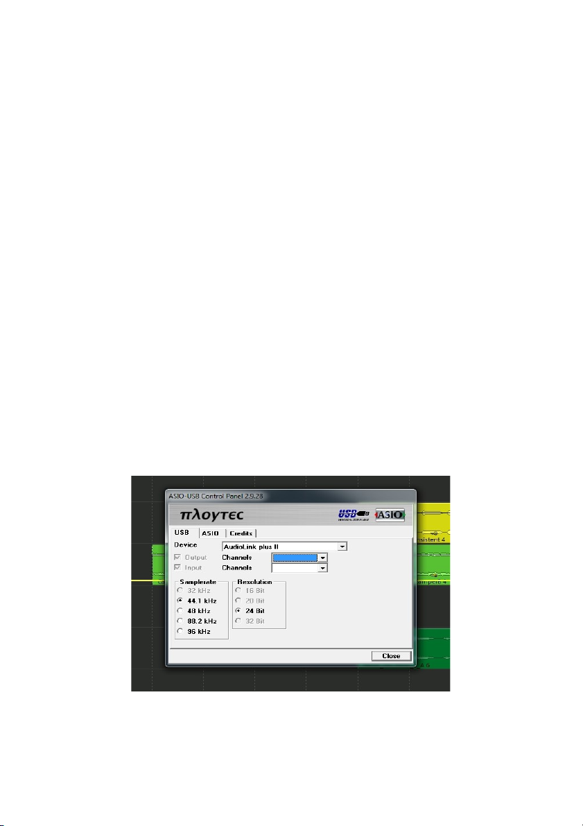
●24 Bit AD/DA Wandler, Sampling Frequenzen 16 Bit und 24 Bit
mit jeweils 44,1 kHz, 48 kHz und 96 kHz, internes 32 Bit
Processing
●Latenzfreies Hardware Monitoring der Inputs 1-4 an Outputs 1-4
●2 regelbare XLR/TRS Combi-Eingänge für Mikrofone und
Gitarre/Bass mit zuschaltbarer 20 dB Anhebung
●4 Stereo-Eingänge (2 x 6,3 mm TRS/Klinken Buchsen)
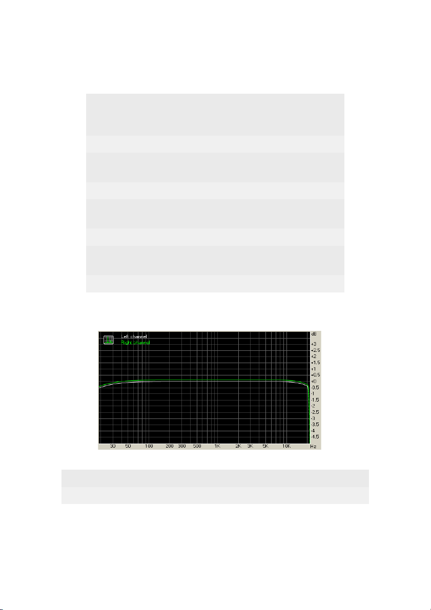
●Dynamikumfang: >96,1 dB (A)
●2 Stereo-Ausgänge (4 x 6,3 mm TRS/Klinken Buchsen)
●100 % USB Powered, d h Stromversorgung über den USB
Anschluss des Computers
●Zuschaltbare Phantomspeisung + 48V für XLR 1 und 2
●Regelbarer Kopfhörer Ausgang 6,3 mm Klinke, Signal-Monitoring
schaltbar für LINE Out 1/2, 3/4, LINE In 1/2 und 3/4
●Anzeige LEDs für Power, Peak, Signal
2

Frequency
response (from 40
Hz to 15 kHz), dB
+0.02, -0.14
oise level, dB (A) -96.2
Dynamic range,
dB (A) 96.1
THD, % 0.0061
THD + oise, dB
(A) -81.4
IMD + oise, % 0.013
Stereo crosstalk,
dB -80.0
IMD at 10 kHz, % 0.042
Frequency response
From 20 Hz to 20 kHz, dB -0.47, +0.02
From 40 Hz to 15 kHz, dB -0.14, +0.02
3

Anschluss und Bedienelemente
Das Gehäuse des Audiolink Pro 24/96 ist eindeutig beschriftet!
Sie finden an der Frontseite die Combibuchsen mit den symmetrischen
XLR/Klinken Eingängen 1 und 2, deren beide Input Level Regler, sowie
einen +20dB Schalter für jeden Kanal Auf der Frontseite ist auch der
Kopfhörer Ausgang mit Lautstärkeregler und Signal-Umschalter Die LEDs
daneben zeigen dabei an, welches Signal am Kopfhörer-Ausgang anliegt
Auf der Rückseite finden Sie 4 Klinken-Buchsen für die LINE Ausgänge 1-
4, daneben 2 weitere Klinken-Buchsen als LINE Eingänge 3 und 4, die DIN
Buchsen für das MIDI I/O sowie 2 Chinchbuchsen für den S/PDIF Digital
Ein-und Ausgang Ebenso ein Schalter für die Phantomspeisung der beiden
XLR Eingänge vorne Auf der Rückseite befindet sich auch der USB 2 0
Anschluss Die 4 LINE Out Buchsen dienen dazu, das Audiolink Pro 24/96
mit Klinken-Kabeln an einen vorhandenen Verstärker oder Mischpult
anzuschliessen Die 4 analogen LINE/In und LINE Out Signale und der
S/PDIF Stereo Anschluss können über den ASIO Treiber in 3 Stereo-Paaren
getrennt angesprochen werden
Der Kopfhörer-Ausgang kann mit dem kleinen Schalter zum Monitoring der
LINE Outs 1-4 und LINE Ins 1-4 verwendet werden
4

Anschluß des Audiolink Pro 24/ 6 an den Computer und
Installation des ASIO 2 Treibers
Der Anschluss des Audiolink Pro 24/96 an den Computer ist denkbar
einfach, verbinden Sie einfach die USB Buchse des Audiolink III mit dem
mitgelieferten USB Kabel mit einem freien USB 2 0 Port Ihres Computers
Da der gleichzeitige Betrieb von 6 Kanälen in bis zu 24bit/96 kHz eine hohe
Bandbreite erfordert, ist das Anschliessen an einen USB 2 0 Port des
Computers erforderlich
Über den USB Anschluß werden die im Audiolink Pro 24/96 digitalisierten
Audiodaten an Ihren Computer übertragen! Das Audiolink Pro 24/96 ist
voll USB-powered, dh es ist auch bei Betrieb mit der Phantomspeisung
keine weitere Stromversorgung oder Batterien notwendig Bei manchen
älteren Rechnern mag für den Betrieb der Phantomspeisung ein Netzteil
erforderlich sein, daher ist ein Netzteil-Anschluss vorhanden
Der Betrieb über einen USB Hub wird von uns nicht empfohlen
Auf unserer Homepage www miditech de finden Sie unter Downloads
neben dieser Bedienungsanleitung auch einen Windows MME/ASIO 2
Treiber für das Audiolink Pro 24/96, der für den Betrieb des Audiointerfaces
erforderlich ist Bitte laden Sie diesen herunter und installieren Sie die
passende Version zu Ihrem 32 oder 64 Bit Windows Betriebssystem
Führen Sie nach dem Download einfach die Setup Datei aus und folgen Sie
den Anweisungen auf dem Bildschirm!
Der Treiber verbessert die Latenzzeiten des Interfaces unter Windows
drastisch, und gewährleistet mit ASIO kompatibler Recording Software
nahezu verzögerungsfreies Arbeiten Nur über den ASIO Treiber werden
alle 6 Kanäle des Audiolink Pro 24/96 greifbar, im MME Modus läuft nur
Kanal 1 und 2
Hier im ASIO Treiber können Sie auch die Latenzzeiten durch das
Einstellen unterschiedlicher Puffergrössen verändern Die Latenzzeit ist u a
Systemabhängig Hier sollte ein möglichst kleiner Wert eingestellt werden,
ohne Störgeräusche zu verursachen Sollten bei der Wiedergabe Knackser
oder Geräusche auftreten, müssen Sie die Latenzzeit des Treibers wieder
erhöhen Je nach der Leistung des Computersystems ist hier „Ausprobieren“
nötig
5

Ebenso installiert sich mit dem ASIO Treiber ein Treiber für das MIDI
Interface des Audiolink Pro 24/96
XLR und Klinken Combo Eingänge 1 und 2
für Mikrofone und Instrumente
Diese Anschlüsse sind Combi-Buchsen, die wahlweise sowohl einen XLR
Stecker als auch einen 6,3 mm Klinkenstecker aufnehmen können An diese
Anschlüsse schliessen Sie vorhandene dynamische oder Kondensator-
Mikrofone an Für ein Kondensator-Mikrofon liefert das Audiolink Pro
24/96 die nötige 48 V Phantom-Speisespannung, wenn Sie den Schalter
dafür auf der Rückseite betätigen (Nur am XLR Eingang) Ein Instrument,
E-Gitarre oder E-Bass wird in der Mitte der Combo-Buchse eingesteckt
Mit dem Gain Reglern neben den XLR/Klinken-Eingängen regeln Sie den
Eingangspegel des Mikrofons oder der Instrumente Wir empfehlen, die
lauteste Einstellung zu wählen, die keine Störgeräusche und Verzerrungen
verursacht! Also etwa mittig beginnen und langsam nach oben vortasten, bis
die Peak LED leuchtet, dann wieder etwas zurück regeln An der roten
Peak-Anzeige auf der Frontseite des Audiolink III können Sie erkennen,
wann eine Übersteuerung beginnt und Sie zurück regeln müssen Der Pegel
der beiden Audio-Eingänge 1 und 2 lässt sich mit dem +20dB Schalter um
20 dB anheben, falls das Signal zu leise sein sollte
6

Kopfhörer-Ausgang (Stereo-Klinke 6,3 mm)
Hier schliessen Sie Ihren Kopfhörer an, um gemachte Aufnahmen oder
Töne aus dem Computer abzuhören Mit dem Drehregler auf der Frontseite
können Sie die Lautstärke des Kopfhörer-Ausgangs regeln
Der kleine Schalter neben dem Kopfhörer-Regler schaltet den Signalfluss
auf den Kopfhörer um, die LEDs zeigen das jeweils anliegende Signal
So ist es z B möglich, im DJ-Betrieb nur die Kanäle 3 und 4 vorzuhören,
während am LINE Out 1 und 2 ein anderer Titel abgespielt wird
Auch kann man hier die an den Inputs 1-4 anliegende Signal per Hardware-
Monitoring auf den Kopfhörer routen, völlig verzögerungsfrei
LINE- Eingänge 3 und 4 (6,3mm Klinke Rückseite)
An diesen zusätzlichen Stereo Eingang können Sie ein LINE Gerät, wie
einen CD-Spieler, MP3 Player oder ein Keyboard mit seinem analogen
Output anschliessen
LINE Ausgänge 1 bis 4 (6,3mm Klinke Rückseite)
Diese führen auf bis zu 4 verschiedenen Kanälen analoge Output Signale
mit LINE Pegel Hier verbinden Sie einen Verstärker oder Mischpult
S/PDIF Interface, koaxial
An diesen beiden Chinchbuchsen stehen weitere 2 Kanäle im digitalen
S/PDIF Format zur Verfügung Hier können Sie z B Einen DAT oder
Minidisk Recorder anschliessen
MIDI Interface
An diese beiden MIDI Buchsen (5pol DIN) können Sie ihre Midifähigen
Geräte, Keyboards, Synthesizer oder MIDI-Expander anschliessen
Änderungen der technischen Daten und des Designs sind
möglich- Für Druckfehler wird keine Haftung übernommen
7

miditech
Audiolink Pro 24/96
High Class 6 In-/6 Out USB 2.0 Audio Interface 24 Bit/ 6 kHz
4 x Line In / 4 x Line Out Stereo Interface
2x S/PDIF In-/Out coaxial
2 x XLR Mic preamp with 48 V phantom power
and input gain control
2 x HI-Z guitar preamps
Low latency hardware-monitoring for LINE In 1-4 and LINE Out 1-4
Adjustable Stereo headphone output
MIDI I/O
USB powered, USB 2.0 high-speed
High class aluminium cabinet
Incl. Miditech free software bundle
ASIO 2 driver
For Windows XP SP3, Vista, Windows 7, Windows 8 & Mac OS X
eMail: [email protected] Internet: www.miditech.de
8

User manual
Thank you for choosing the Miditech Audiolink Pro 24/96
We think you’ll find your Miditech product to be an extremely flexible,
high-performance tool for your computer-based hard disk recording system
What You Should Have Received in the Box
When you opened the box, you should have found the following:
• An audio interface box
• A USB cable
• An Owner’s Manual
System Requirements
In order to use Audiolink Pro 24/96, you’ll need the following:
• A desktop or laptop computer with:
• Windows XP Service Pack 2 or newer operating system
• An unused USB 2 0 port
• A minimum 512MB RAM
• A fast, high-capacity IDE, SATA
• Peripheral audio equipment, such as a mixer, microphones, studio
monitors, musical instruments, etc
Installation
Complete installation consists of logging in as an administrator, installing
the Windows drivers into your system, connecting the audio interface to a
USB port and then connecting your Audiolink Pro 24/96 to any other
peripheral audio equipment
You need to download the driver from www miditech de !
To install your Miditech product you must be logged into your computer as
an administrator You can either log in with the account called
"Administrator” or with any other account that has administrative
privileges Otherwise, you will not be able to install the hardware and
drivers Important — check the Miditech website for software updates
You should always check our website www miditech de for the latest driver
updates before installing your Audiolink Pro 24/96 Just go to the driver
downloads area and find the Audiolink Pro 24/96 section
9

Installing the Audiolink Pro 24/ 6 software
Now that you have logged in as an administrator you are ready to install
your Audiolink Pro 24/96 product in your computer
Install the drivers
You should do this before connecting the Audiolink Pro 24/96 Interface to
the USB port on your computer To install the downloaded driver, double-
click “setup exe” on the icon and follow the instructions To connect the
Audiolink Pro 24/96 and gets it`s full high-speed functionality, you must
use an USB 2 0 port The Interface is compatible to USB 3, but it do not use
this bandwith
Please plug your Audiolink Pro 24/96 to the USB port in the following
windows, and then continue with the Installation Plug one end of the USB
cable into the USB connector on the rear of the Audiolink Pro 24/96
interface Attach the other end of the USB cable to an open USB 2 0 port on
your computer
ASIO Control Panel
After the installation you can find in each ASIO compatible recording
software the Audiolink Pro 24/96 ASIO control panel There you can setup
the ASIO driver speed
10

Note: Shorter latency time will occupy more CPU source,
4~11msec for average PC If you hear some “POP…”, please
drag it higher to 8~20msec
Product overview:
The Audiolink Pro 24/96 audio interfaces contain a wide variety of
connections that allow great flexibility in operation
Analogue inputs and outputs
Audiolink Pro 24/ 6’s front panel
1 Two universal inputs (1 – 2) with meters and trim knobs The universal
input connections can accept balanced or unbalanced signals via ¼”or XLR
connectors Since your Audiolink Pro 24/96 has built-in preamps, you can
just plug your microphone or guitar cable right into the universal input No
external preamp direct box, or mixer is needed!
2 Two signal indicated LEDs: The Red one shows the input signal too high
and it will be cut the peak, while the Green one shows the input signal is
11

available For optimal audio quality, you should adjust the input trim knob
so that your loudest recorded signal lights up the yellow light, but not the
red When the red meter light shines extra bright – you’ve clipped! If the
signal level ever exceeds 0dB FS the signal will be “clipped” and you
will hear a “pop” or “tick” in the recording This is a very bad thing, and
clipping should be avoided at all costs! There is enough headroom so
that you can be conservative in this area, and there is no need to push
the input levels right up to the edge of clipping
3 Gain selector switch: if the switch is down, the voltage of signal will be
enlarged 10 times It always used in the mic in situation
4 There is also an 1/4” stereo monitor headphone output jack, with a
corresponding volume knob, and you also can select “analog output
1/2” , “analog output 3/4”, “analog input 1/2”, and “analog input 3/4” with
the button by side, the LEDs will show which it is
Audiolink Pro 24/ 6’s rear panel:
1 Power Supply Jack: DC 6-9V input If Power Supply on the USB port is
not enough, please use the an external Power Adapter for power supply
Especially when you use the phantom power(+48V)
2 USB Jack, please connect it to the USB 2 0 port On PC with the USB
cable
3 A phantom power switch (+48V) and an amber power indicator light
To enable phantom power, press the button labeled +48V (the +48V
LED will light up) and phantom power will be provided to the microphone
inputs 1-2 Phantom power will not be applied to any line level equipment
or guitars plugged in using cables with ¼” connectors
4 S/PDIF In & Out Interface:
These S/PDIF connectors are used to transmit digital audio data between
digital audio devices via an electrical signal When connecting devices to
the S/PDIF jacks, the use of standard analog RCA audio cables is not
recommended For reliable S/PDIF operation, 75-ohm coaxial cables are
recommended This port is no 5-6 in the ASIO driver
5 MIDI In & Out Interface:
The MIDI ports can be used for receiving MIDI time code (MTC), or
12

sending and receiving MIDI signals between your digital audio/MIDI
sequencing software and external sound modules, keyboards, MIDI
controllers, etc And the MIDI cable is standardized and widely available
6 Two analog line inputs (3-4) and four analog line outputs(1-4)
These analog inputs (3 – 4) operate with an input impedance of 10Kohms
The input and output connections can be used with balanced or
unbalanced cables via the ¼” connectors By default, the inputs and
outputs are set to receive or send a +4dBu signal
Contacting Miditech Customer Service
If you experience any trouble with your Miditech hardware please go to
the supportarea of our website at www miditech de and check out the
FAQ’s we have there If you can’t find a solution to your problem there,
please contact technical support via email at info@miditech de !
There is an exampleform that can be copied and sent to our technical
support staffand they will respond to you quickly
The best way to get the help you need isby giving us plenty of detailed
information about your computer system, your audio software and
hardware, and the problem you are having
We do ask you to please read through this manual and the support area of
our website before contacting us
Thank you for buying Miditech products!
13

Technical specifications:
Frequency
response (from 40
Hz to 15 kHz), dB
+0.02, -0.14
oise level, dB (A) -96.2
Dynamic range,
dB (A) 96.1
THD, % 0.0061
THD + oise, dB
(A) -81.4
IMD + oise, % 0.013
Stereo crosstalk,
dB -80.0
IMD at 10 kHz, % 0.042
Frequency response
From 20 Hz to 20 kHz, dB -0.47, +0.02
From 40 Hz to 15 kHz, dB -0.14, +0.02
14

Important Safety Instructions
1 Read Instructions – Be sure to read all of the safety and operating
instructions before operating this product
2 Retain Instructions – The safety instructions and owner's manual
should be retained for future reference
3 Heed Warnings – All warnings on your Miditech product and in the
Owner'sManual should be followed
4 Follow Instructions – All operating and use instructions should be
followed
5 Moisture – Water and moisture are detrimental to the continued
good health of your Miditech product Do not install or operate your
Miditech product near sources of water or moisture such as sinks,
damp basements, leaky roofs, etc
6 Heat – Your Miditech product should be situated away from sources
of heat such as heaters or radiators
7 Grounding –Precautions should be taken so that the grounding
capabilities of the unit are not undermined The Audiolink Pro 24/96
provided with a cord with an equipment grounding conductor and
grounding plug This plug must be plugged into an outlet that is
properly installed and grounded in accordance with all local rules and
ordinances Do not modify the plug provided with the equipment If the
plug will not fit into your outlet, have a proper outlet installed by a
qualified electrician
8 Power Cord Protection – Power supply cords should be routed so
that theyare unlikely to be walked on or pinched by items placed upon
or against them Pay particular attention to protecting the plugs, outlets
and the point at which the cord exits your Miditech product
9 Servicing–Do not attempt to service this unit yourself, as opening
the case will expose you to hazardous voltage or other dangers All
servicing should be referred to qualified service persons
15
Table of contents
Languages:
Other Miditech Accessories manuals