Philco 643 User manual

• • • •
SERVICE BULLETIN
No. 226
For Members of
RADIOMANUFACTURERS
SERVICE
A PHILCO SERVICE PLAN
Model 643
General Specifications
TYPE CIRCUIT: Superheterodyne, with Class "13"
output; built in connections for Philco All-wave aerial; aerial
selector huilt into and operated by wave-band switch.
POWER SUPPLY: Battery operated Model 643 uses a
2-rnlt storage battery (Philco 172-R). Model 643-A uses
dry A battery (Philco 41-8006). Both sets use a dry combina-
tion "B" and "C" battery unit (41-8061). This has a socket
into which the plug on the battery cable attached to chassis
is to be inserted.
TUBES USED: 1 type 34, pre-selector; 1 type 1C6, Detector-
Oscillator; 1 type 34, I. F.; 1 type 30, 2nd Detector and
A. \·. C.; 1 type 32, 1st A. F.; 1 type 30, driver; 1 type 19
output. Model 643-A has also a ballast tube, type lCl, to
maintain constant filament voltage on all tubes. The socket
for this tube exists in both 643 and 643-A chassis, but in the
former, the type lCl tube is not used, and the filament
contacts of the socket are shorted by a metal jumper.
WAVE BANDS: Four-(1) Longwave (U. S. weather
forecasts); (2) Standard; (3) Police; (4) Shortwave.
COVERAGE OF EACH BAND: Band 1, 150-390 K.C.;
Band 2, 540-1750 K.C.; Band 3, 1.75 to 5.8 megacycles;
Band 4, 5.8 to 18.0 megacycles.
TUNING DRIVE: Dual planetary, ball bearing, 80 to 1
ratio for slow speed tuning.
TONE CONTROL: 3-Position.
INTERMEDIATE FREQUENCY: 460 K.C.
CURRENT CONSUMPTION: "A" battery, .750 M.A.;
"B" battery, 22 l\l.A.
34
I .F.
6ALLAST FO O
I-C-18]'
(64)-.t.Ol'l\.'I') C,
Fig. 1. Tube Sockets as viewed from bottom
Adjusting Compensating Condensers
Adjustment of compensating condensers in Model 643
requires an accurate signal generator covering long-wave,
standard wave, police and short-wave frequencies. The
PHILCO Model 088 All-Wave Signal Generatcr, having
a continuous range of from 100 to 20000 K.C., is ideal for
this purpose.
An output meter is also needed. PHILCO Model 025
Circuit Tester includes a high grade output meter.
Fig. 2. Locations of Compensating Condensers
Philco No. 3164 fibre wrench and No. 27-7059 fibre-handled
screwdriver complete the equipment needed for making these
adjustments. The locations of the various compensating
condensers are shown in Fig. 2. Connect the output meter to
the plate and cathode contacts of the type 30 driver tube
(using the adapters provided with the "025") and set it at
the 0-30 volt range.
I.F.-Set the signal generator at 460 K.C. \\·ith attenuator
set at minimum, and attach its antenna lead to the grid cap
of the 34 I.F. amplifier tube (removing grid lead). Connect
ground lead to ground terminal on set or some part of chassis.
Set the dial at 55 and turn the waveband s,1·itch to position
2 (standard). Adjust the volume control of set to almost
maximum (just before oscillator hiss becomes noticeable),
and the 088 attenuator so that about one-fourth (¼) scale
reading is had on the output meter. With a fibre screwdriver
adjust condensers@ and@ (2nd I.F.) for maximum reading
on output meter. Turn attenuator of signal generator to
minimum and remove its antenna lead from the grid of the
34 I.F. tube, placing it on the grid of the 1C6. Adjust 088
attenuator as before then proceed to adjust condensers
@and@ (1st I.F.) for maximum reading. Then remove the
088 oscillator lead and replace grid connection. Care should
be taken to keep the output meter reading during adjustments
at about one-fourth scale reading. This should be done by
using the 088 attenuator control.
WA VE TRAP-Connect the Signal Generator antenna
and ground lrnds to the antenna and ground posts of the
set. With the signal generator operating at 460 K.C. and
the set controls adjusted as before for I.F. alignment, adjust
wavetrap (i) until a minimum reading is obtained in the
output meter.
SHORT WAVE~In adjusting the short wave or high
frequency band, the R.F. compensator will have a tendency
to "pull" or change the frequency of the oscillator. By
shunting a padding or variable condenser across the oscillator
section of the gang and tuning it so that the second harmonic,
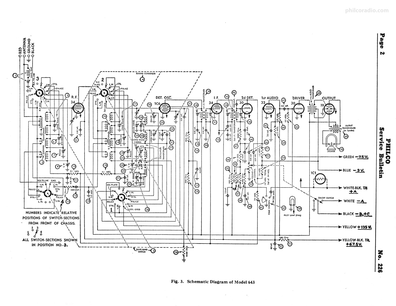
(Continued on fourth Page)
philcoradio.com

-r 0
~
zlll!
w :::,u
0 .... 0 <
U.I z a!. ..J
o!--tl.7m
i
?
,,r--------------
,' 2
~
l\JNi~CONofNSER--r----
1 R.F. I ------
,Pl.AT£◊
LW -¼- / ---7
, .. sm. \.!} I ,
I I
I I
I I
/ /
~
I
I I -~
/ DET.OS<:.. t !~
I I
,
~
~
-ro
~
\ \ '
~
I~,1 ,.,
~
(36 .
~
l
u
1
ai
"' SJO. Ji]1100MMF
,~" y~ , ..w. \
\ POCIC£ §).._
~
~~
\ S.~ )~,
\ \
\ \
\~
@
L.W. 0 0 \ys.W.4
~ ~
\\ POLICE ~1 \ P0LIC.E \ ' \ \
\ ). \ STD-rJ:•r\ ..W.
~
\. · .; "-...iosc.C.l\1D 30
NUMBERSINDICATE RELATIVE ' 1 ' i,
' ' I \ '
POSITIONSOF SWITCH-,SECTIONS \ \ I\I
.a..1
s~""'
51 '@
t
O•j!J
O 68
~tOUTPUT
[a]
=TlA=EI -t'.,..i.,1
~
~~
_@ GREEN-7.SV.
/
- _c:: -- -,
,....... I
,i<!i I
,_°i I
g d l
<!i
~
L.
?
~
',, L-+......--t----.,.. WHITE-BLK.'DJ
l) 'I-~
~
--+--.-~ ..',
~
i ;~tilt ',,,'if- :WHITE ::A_
.' ~\ l~'! - .,~'® • BLACK=!,-!£.
~
PILOTLAMP (OIAJJ
l~b .BLUE-3V.
:V1
I
FROM FRONT OF CHASSIS. \ \ 'I,
i 3 '\ \ \ \ I I I I I
~
YELLOW'±.!ll
i ,~ \ \ \ \.
\ \ \ \ 10000~-
ALL SWITCH-SECTIONSSHOW':' \ \ \ V .Ali> -YELLOW-BLK.TR.
IN POSITION N0.-3. \..:__________ ---~-r- _-~'------ ____ -r--'.. ~T'@) 71 +67.5V,
'-,!IAVilAND-0 ~~>'t5
~
• SWITCH &· ">!
7
Fig. 3. Schematic Diagram of Model 643
-u
DI
CQ
ft
N
fl!
ft
..
~--u
ft :a
ft ...
tit t"'
r::n
_o
;;
..
....
1::1
I=
•
N
N
0,
philcoradio.com

No. 226 PHILCO
Service Bulletin
Replacement Parts for Model 643
Description
@ Resistor (8000 ohms).
@ Resistor (2000 ohms).
@ Resistor (5 t.000 ohms) .
@ Electrolytic Condenser.
@ Condenser (0.05 mf.).
@A Condenser (.05 mfd.).
@ 1st I.F. Transformer.
@ Padder(.
@ Padder)
@ Condenser (Twin 0.05 mf.) .
@) 2nd I.F. Transformer.
@ Padder(
@ Padder)
@ Condenser (Mica 6000 mmf.) ...... , .... .
@ Resistor (50,000 ohms) ..
@ Resistor (.5 meg.).
@) Condenser (Twin 110 mmf.) .
@ Condenser (.05 mf.).
@ Condenser (.01 mf.).
@ Rcsi stor (1 meg.) ................•..•.......
@ Volume Control and Switch.
Fig. 4. Bottom View of Chassis @ Resistor (2 meg.) ..
@ Resistor (1000 ohms).
(D
®
0
0
0
©
0
®
®
@
@
@
@
@
@
@
Description
Wave Trap Aesembly. , .
Wave Band Switch.
Antenna Transformer.
Condenser Gang Assembly.
"""}
Padder
Padder
Padder
Condenser (.05 mfd.).
Resistor (100,000 ohms).
Condenser (.05 mfd. tubular).
Condenser (Mica 1800 mmf.).
Resistor (500 ohms).
Condenser (Mica I 10 mmf.).
Resistor (100,000 ohms) ..
R.F. Transformer.
Part No
38-6850
42-1128
32-1806
Jl-1634
.... Part of 32-1806 @
3615-SG
6099
30-4020
6018
33-1207
30-1031
6099
32-1807
@ Padder}
@ Padder
@ Padder
@ Padder
. . . . . . . . . . . . . . . . . . . . . . . Part of 32-1807 @
®
@
@
Condenser (Tubular .05 mf.).
Condenser (Mica 3250 mmf.).
® Pa<lder
Paddcr}
@ Padder
@ Padder
@
@ Oscillator Transformer.
Condenser (Mica 600 ,mmf.).
30-4020
30-1061
. . . . . . . . .Part of 32-1808 @
32-1808
30-1049
31-6027
Ll3t
Price
$1.10
2.50
3.25
5.50
.35
.20
.35
.40
.20
.35
.20
3.00
.35
.45
2.50
.35
.70
@ Resistor (1000 ohms).
@ Resistor (50,000 ohms) .
@ Pilot Lamp.
@ Condenser (.01 mf.) ...... , ................. .
@ Resistor (2 meg.) .
@) Tone Control.
@ Condenser (0.3 mf.).
@ Resistor (330,000 ohms) .
@ Resistor (250,000 ohms).
@ Resistor (500,000 ohms) .
® Condenser (0.01 mf.).
@ Input Transformer.
@) Output Transformer.
@ Voice Coil and Cone Assembly (K-7).
@ Resistor (1000 ohms).
Battery Cable Assembly.
Tube Shield Base (2).
Tube Shield Base (3).
Tube Shield Body (2) ......... , .. .
Tube Shield Body (3).
4-prong Tube Socket (5) .
5-prong Tube Socket (1).
6-prong Tube Socket (2).
Speaker Socket (I) ..
Dial Scale .
Knobs (IJ.
Knobs (I) .
Knobs (2).
Knobs (I).
Bezel.
Bezel Glass.
Page 3
Part No.
5838
6984
6098
30-2127
3615-SG
3615-SG
32-1809
Part of@)
3615-DU
32-1810
Part of@
6359
6098
4410
30-1031
3615-SU
3903-SU
33-1096
33-5119
33-1025
33-1028
33-1028
33-1028
6098
5316
3903-SG
33-1025
30-4352
6287-DG
6046
4410
6097
3903-SU
32-7473
32-7472
36-3159
5837
41-3144
28-2725
8004
28-2726
8005
27-6044
27-6042
27-6036
27-6043
27-5124
27-4206
27-4207
27-4208
27-4219
28-29.H
27-8009
27-7972
List
Price
.20
.20
.20
I.SO
.35
.35
I.SO
.40
2.00
.60
.20
.20
.35
.35
.25
.20
1.10
.20
.20
.20
.20
,20
.35
.25
.20
.75
,40
.20
.20
.20
.25
1.75
I.SO
.80
.20
I.SO
.03
.01
.to
.10
.10
,10
,11
.08
.25
.12
.10
.10
.to
,55
,55
@ Padding Condenser.
@ Padding Condenser ..
@A Padding Condenser.
OIOOO-R .45
Bezel Frame Gasket ..
Chassis Mounting Screw .
Chassis Mounting \Vasher.
Chassis Mounting Cushion .
'"A" Battery ..
. .... W-1496-H 1.60 per C.
@ C.·ondcnser (Mica 15 mmf.).
Q<,J Conienser (Mica 15 mmf.).
0:tl Con<lenser (Tuhnlar .01 mf.).
04000-F
30-1030
30-1030
30-4145
.25
..,s
.35
.25
. . 27-4021 1.40 per C.
27-4202 .03
172R
"B" and ·•c" flattery .. P9068
philcoradio.com

Page 4 PHILCO
Service Bulletin No. ZZ6
Adjusting Compensating Condensers
(Continued from first Page)
instead of the fundamental, beats with the incoming signal,
this "pull" can be minimized. The procedure for tuning this
band is as follows:
Set the dial of the receiver at 18 megacycles (top scale}
and the 088 dial at the same frequency. Connect the shunt
condenser to the oscillator section of the gang and tune it so
that the second harmonic of the oscillator beats with the
18 M.C. signal from the 088. Next tune padders @)and®
(antenna and R.F.) for maximum reading of the output meter.
Disconnect shunt condenser and tune padder @ (osc.) for
correct dial calibration. The oscillator frequency, when cor-
rectly set, will be higher than that of the incoming signal and
the image frequency lower. In order to check this it should
be possible to tune the image at approximately 17.1 M.C.
by increasing the input from the 088 oscillator.
For the low frequency adjustment of this band, turn the
dial to 6.0 M.C., set the signal generator at 6.0 M.C. and
adjust condenser@ for maximum reading. This compensator
is underneath the chassis and reached from underneath.
POLICE BAND-Turn waveband switch to position 3
from left (police band); set dial at 5.5 and signal generator at
5500 K.C. Adjust condenser@, @and 0 for maximum reading
(osc., R.F. and Ant.). Turn dial to 1.8 and signal generator
to 1800. Then adjust condenser @ (nut) for maximum
output reading.
STANDARD WAVE-Turn waveband switch to position
2 (standard broadcast), set signal generator at 1500 and dial
of set at 150. Now adjust the oscillator, R.F., and antenna
"Standard" condensers. These are@, @)and®• respectively.
Now turn the dial to 60, set signal generator at 600 and
adjust condenser @A (oscillator standard-series) (screw) for
maximum reading.
LONG WAVE (Weather) BAND-Turn waveband switch
to position 1 (left) (Longwave). Set dial at 35 and signal
generator at 350 K.C. Adjust condensers @, @ and ®
(oscillator, R.F., and Antenna Longwave) for maximum
reading. ·
Turn dial to 17, signal generator to 170 and' adjust con-
denser @A (longwave series) for maximum reading.
In making these adjustments be sure that the signal level
from the 088 is kept as low as possible. If the dial calibration
is off, go over the low and high frequency padders in the
oscillator circuit of each band until this is corrected.
Are You Using to Advantage
The NEW PHILCO PARTS KITS
Complete Pilot Lamp
Assortment
Part No. 45-1166 List Price $13.80
These new parts kits present a
wonderful opportunity to improve
your service business 1 IF PROPERLY
USED. Their advantages lie in the
fact that, (1) they cover ALL Philco
models, and (2) the chart in the lid
of the carton is a complete replace-
ment guide to enable quick selection
of the part needed.
By having a complete set of these
kits on your service counter and in
your stock room, you will save hours
of your men's time and at the same
time be sure the customer gets the
correct GENUINE PHILCO PART.
In addition to those illustrated here,
many other kits are available, listing
practically all types of parts.
Complete Input Transformer
Assortment
Part No. 45-1158 List Price $42.05
PHILCO RADIO & TELEVISION CORPORATION
Parts and Service Division
August, 1935 Printed in U. S. A.
philcoradio.com
Other Philco Radio manuals

Philco
Philco 121 User manual

Philco
Philco 96 User manual

Philco
Philco 121 User manual

Philco
Philco PRR1005BT User manual

Philco
Philco 37-650 User manual

Philco
Philco 121 User manual

Philco
Philco 77 User manual

Philco
Philco 80 User manual

Philco
Philco PHOTOFACT 49-1150 User manual

Philco
Philco 200 User manual