Midland ML802 User manual

1
ML802
Instruction Manual
UHF CB MOBILE RADIO
with Remote Speaker Microphone

2

3
CONTENTS
Specications.................................................................................................................................................03
Introduction.................................................................................................................................................. 04
What’s Included............................................................................................................................................ 05
Emergency/Telecommand Channels......................................................................................................... 05
Features..........................................................................................................................................................06
General Operation........................................................................................................................................07
Appendix: Frequency/CTCSS/DCS List....................................................................................................15
Notes...............................................................................................................................................................17
Warranty.........................................................................................................................................................20
SPECIFICATIONS
Output Power: UHF/CB 4.6-5W, LMR 13-17W
CB Channels - RX/TX: 80
CB Frequency Range: 476.400-477.400MHz for Bank1
450-520MHz for Bank2
Channel Width: 12.5kHz (Narrowband)
Power Source (nominal): 13.8V
Max Absorption Current in TX: 1.3A (5W), <3.2A (15W)
Microphone: MK802 w RJ45 Connector
Base Speaker Power: 2W Max
Digital Coded Squelch (DCS): 104
Interference Eliminator CTCSS: 50
Duplex Capability: Yes
Channel Memory Scan: Yes
LCD Display: Segment
Backlit LCD & Keypad: Yes (7 Colour Adjustable)
External Speaker Jack: Yes
TX/RX Indicator: Yes
Scanning Receive Functions: Yes
Key Lock: Yes
Key Beep On/O: Yes
Auto Squelch: Yes
Dimensions (excl Bracket): 110W x 28H x 112D mm
Typical Range: 18km Line of Sight
Max Operating Temperature: 50° (Temperature test executed according to
the current law that allows a value up to 55°)

4
INTRODUCTION
ank you for purchasing this MIDLAND in-vehicle HYBRID UHF/CB radio.
Please read this manual carefully to understand its functions and operations.
e ML802 you purchased is an advanced UHF in-vehicle two way radio.
ML802 combines the very latest in electronic hardware with the most up-to date computer aided
design and manufacturing techniques to produce an extremely compact mobile radio with
outstanding specications and performance.
ML802 has remote controls built into the microphone. e radio is designed for unobtrusive
mounting in modern vehicles with limited space. Its innovative features include built-in
loud-speakers housed within both the extremely compact base and the remote microphone.
Note: e use of the Citizen Band radio service is licensed in Australia by ACMA Radio
Communications (Citizen Band Radio Stations) Class license and in New Zealand by the Ministry of
Economic Development New Zealand.
ank you for your support and interest in our products!
Maintenance service and support
e Company provides long-term support for its products. is support includes maintenance,
spare parts and warranty within the warranty period.
Aer the expiry of the warranty
e company provides technical services and spare parts to authorized radio dealers.
e ordering of replacement parts
When ordering replacement parts or equipment information, please specify the complete part code.
All parts include part number, components or chassis. If you do not know the part code, please
indicate the chassis or group that the part relates to.
Personal safety
For personal safety, please disconnect all power and RF cables before attempting any repair work.
All articles displaying this symbol on the body, packaging or instruction manual must not be
thrown away in normal waste bins but should be placed in recycling bins or taken to a specialised
waste disposal centre.
is symbol assures that a device complies with all applicable ACMA regulatory arrangements
for radiocommunication equipment used in Australia.

5
WHAT’S INCLUDED
Please carefully unpack the transceiver from the carton. Please check that all accessories are included.
SPARE PARTS UNITS QUANTITY
In-vehicle radio pc 1
Mounting brackets (U and Quick Release) pc 2
Microphone pc 1
Microphone bracket pc 1
Microphone extension cable (2m) pc 1
User manual pc 1
Power cable pc 1
Power adaptor cable pc 1
Screws pc 1
Please contact the retailer if any parts are missing.
Emergency Channel
ACMA has pre-allocated channels 5/35. Channel 5 is only for emergency application. Channel 5
repeater access is available in most areas. Activate duplex on Channel 5.
Telecommand Channels
ACMA has reserved Channel 22 and Channel 23 as telecommand channels. Transmission is
prohibited on these channels. ML802 blocks transmission on these 2 channels. Channels 61, 62 and
63 are for future use and TX is inhibited on these channels.
Commercial UHF-LMR
e ML802 features hybrid funcionality allowing high power (13-17 Watt) use on UHF-LMR
commercial frequencies. Please note that according to ACMA regulations this is only permissable
for authorised commercial license holders. Activation of this high power LMR function can only be
done with licensed Midland soware available through authorised dealers and agents.

6
FEATURES
Microprocessor Controlled Frequency Synthesiser
Allows user programmable control of scanning, channel memories and selected options.
Scanning Function
Quickly nds radio channels.
Individually Programmable DUPLEX Function
Selectable only for individual channels in areas that can access a repeater. is leaves others free for
use as simplex channels.
High Contrast Liquid Crystal Display
Fully detailed LCD provides a visual indication of the selected channel and all selected functions.
Backlit for night viewing.
Compact Size
Fits into the smallest locations allowing installations in space challenged environments.
CTCSS & DCS
A built-in Continuous Tone Coded Squelch and Digital Coded Squelch System option provides quiet
channel operation.
Overvoltage Protection
Special overvoltage detection circuitry protects the radio and warns of excessive voltage conditions
by ashing the display.
Surface Mount Technology
e very latest surface-mount components, design, assembly techniques and quality control
procedures are used to ensure high performance and reliability.

7
GENERAL OPERATION
1. LCD
2. Mic/Programming Socket
3. Menu
4. Call
5. Function Select
6. Key Lock
7. Mic
8. Priority Channel
9. Monitor
10. Scan
11. T/R LED
12. Speaker
13. Channel Down
14. Power
15. Channel Up
16. PTT (Press to talk)
17. Mic Connector
18. USB Port (Charging)
About Banks
e radio is designed with 2 bands. BANK1 is xed to low power (LCD does not display Lo for 80
UHF/CB channels). e frequency range is: 476.425 - 477.4125MHz. Channels 1-80 are xed for
Australian frequencies. BANK2 450-520MHz LMR frequency for Channels 81-99. ese channels
can be programmed using optional programming soware available to authorised dealers.
ey can also be switched to high and low power (LCD will show Hi/Lo).
BANK1 and BANK2 switching mode: LOCK + MON, the liquid crystal display will show P1
(bank1), P2 (bank2)
Power
To turn on, briey press the key for three seconds.
To turn o, briey press the key for three seconds.
Key Lock
With radio in standby, press for three seconds. en the LCD will display icon.
To unlock press button for three seconds.

8
When radio is in key lock, only the volume function can be adjusted. e radio mode will display
“LC” if any button is pressed.
Volume
Press the or keys to increase or decrease the volume. e radio will beep with each key press
and the display will ash to indicate the volume setting. e volume level can be set from 00 (min) to
09 (max). e display will stop ashing and return to the selected channel display a few seconds aer
the last volume adjustment.
Selecting Channels
Press the or keys to step up or down through the channels.
Transmitting
To transmit, press the PTT button. Hold the microphone about 5-8 cm from your face and speak at
a normal voice level. e microphone is quite sensitive so it is not necessary to raise your voice or
shout. Release the PTT when you have nished talking.
Important: Always listen to ensure the channel is free before transmitting.
CTCSS (Continuous Tone Coded Squelch System) and DCS (Digitally Coded Squelch)
CTCSS (Continuous Tone Coded Squelch System) and DCS (Digitally Coded Squelch) are squelch
quieting systems that allow several groups of users to share the same channel without disturbing
each other. e system applies a continuous low-level tone to your transmission and uses a matching
tone decoder to control your receiver’s Squelch. With CTCSS or DCS enabled, the channel remains
quiet to all incoming signals unless they carry the correct tone. When a transmission with the correct
tone is received, the squelch opens and remains open for as long as the signal is present. When the
transmission ends the channel becomes quiet again. Transmissions that do not use the correct tone
will not to be heard. ere are two tone sets installed in your ML802 comprising 50 CTCSS and 104
DCS user-selectable tones.
e ML802 allows CTCSS or DCS to be enabled or disabled on individual channels.
Note: e CTCSS/DCS tone you select will be used for all CTCSS/DCS enabled channels in
your radio.

9
Selecting the CTCSS or DCS
Choosing which tone to use will probably be dependent on the other radios you talk to. If you talk to
others outside your group who already use CTCSS or DCS tones you will need to select the tone that
matches theirs.
e ML802 includes most of the commonly used tone sets.
If the users you talk to don’t currently use CTCSS or DCS, choose your own tones.
ere is no dierence in performance between the two tone sets.
e CTCSS and DCS tones are stored in your radio in a sequential table. e rst table location is
OFF. e next 50 locations are CTCSS tones followed by 104 DCS tones.
OFF -> CTCSS 01 to CTCSS 50 OFF-> DCS01 to DCS 104
To Select CTCSS Tone
1. Briey press MENU key to enter the MENU function.
2. en press or in the menu to enter your choice.
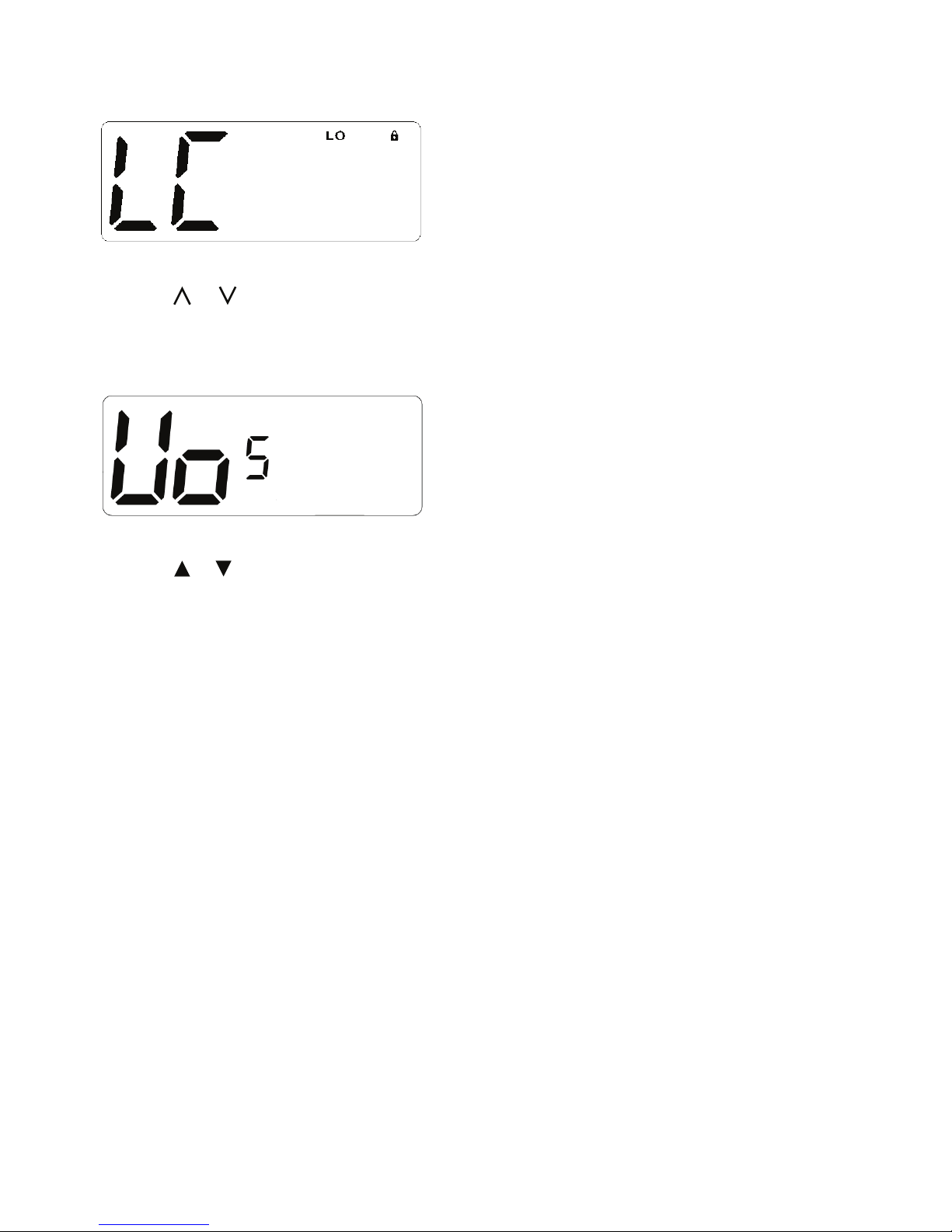
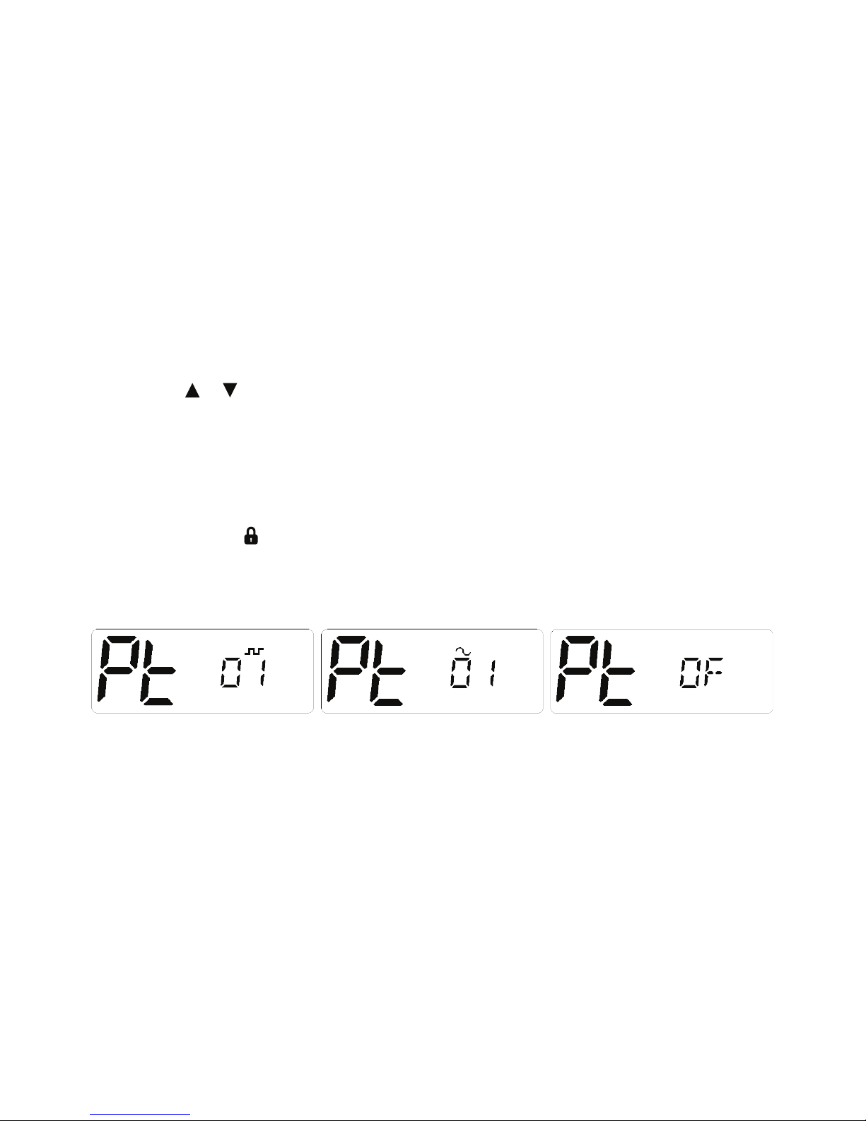
en press the Lock key on the handset to enter the sub-audio selection menu, then select the
category by pressing the handset’s function selection key, ~ represents CTCSS (analog sub-audio),
DCS (digital sub-audio), OF represents no sub tone.
(e unit provides 50 sets of CTCSS and 104 sets of DCS).
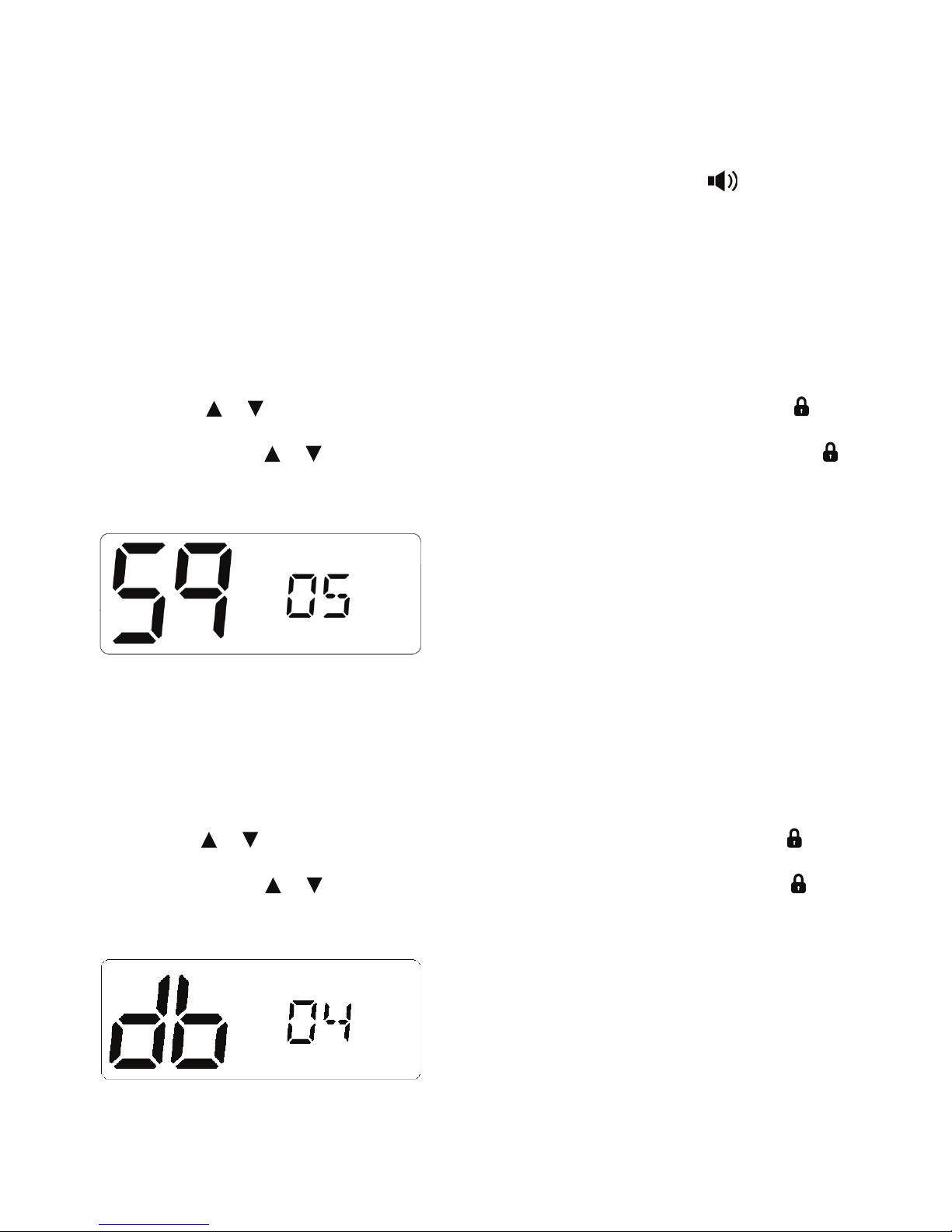
3. Aer selecting the sub-audio category you want to set, press the Lock key to conrm your choice.
4. en press the handset function select button to conrm the selection of the desired sub-audio
group, and then press to conrm your choice.
Note: If you select a CTCSS personal code, the previously set code will be canceled.
In the channel 5 and channel 35 is not allowed to set sub-audio, this feature is invalid.
Once a DCS or CTCSS code is selected, your radio will now be in “Silent” mode on that channel
and will remain muted in that channel unless a signal containing your selected CTCC/DCS tone is
received. Channels that do not have CTCSS/DCS enabled will remain open to all signals.
You may activate CTCSS/DCS on as many channels as you wish except channel 5 which is designated
for emergency use.
Note: CTCSS/DCS may not work through some repeaters.
To Monitor the Channel
Briey press the “MON” key. If there are no signals present, you will hear the usual hiss of an empty
channel. Press the “MON” key again to restore the Squelch to its previous setting.

10
Squelch Control
Squelch control is used to eliminate the background noise when there are no signals present. e
ML802 features a preset Squelch system. e Squelch sensitivity has been factory set to provide
optimum performance in most environments. e sensitivity can be altered by the user if required to
suit varying environmental situations. e Squelch can be opened or closed by pressing the “MON”
key. When the Squelch is open, the receiver’s background noise can be heard and is displayed.
When the Squelch is closed, the receiver remains quiet when there are no present signals but an
incoming signal will override the squelch and be heard through the speaker.
To Open the Squelch
Briey press the “MON” key again. A low beep will be heard. If there no signals present you will hear
the receiver’s background noise.
To Adjust the Preset Squelch Sensitivity
1. Briey press the MENU key to enter the menu .
2. en press or key to select and stop when the LCD display “Sq”, and briey press the key
to conrm and enter squelch sensitivity setting.
3. en you can press or key to choose the squelch sensitivity level you want, and press the
key to conrm.
e default setting is 05 which generally provides reliable squelch operation for most applications.
Squelch Sensitivity
e sensitivity of the Squelch to incoming signals can be set to suit your operating environment.
For example, excessively noisy environments may cause the squelch to open on local noise.
e ML802 has nine preset Squlech sensitivity settings.
Backlight
1. Briey press the MENU key to enter the menu.
2. en press or key to select and stop when the LCD display “db”, and briey press the key
to conrm and enter backlight setting.
3. en you can press or key to choose the desired backlight color, and briey press the key
to conrm.
Select ‘OFF’ or one of the 7 colour options: Green, Red, Yellow, Blue, Cyan, Magenta, White.

11
Duplex Operation
Press and hold the MENU key on channels 1-8 and channels 41-48 to enable the Duplex operation.
Duplex operation allows the radio to transmit on a dierent frequency to that which it receives
allowing operation through repeater stations. Repeaters automatically retransmit your signal over a
wider area providing greatly increased range. Duplex operates only on channels 1-8 & 41-48. When
duplex is selected on these channels, the radio receives on that channel but actually transmits 30
channels higher. In repeater mode, the radio only operates on repeater channels.
Channel Selecting 1 2 3 4 5* 6 7 8
Receiving Channel 1 2 3 4 5* 6 7 8
Transmitting Channel 31 32 33 34 35* 36 37 38
Channel Selecting 41 42 43 44 45* 46 47 48
Receiving Channel 41 42 43 44 45* 46 47 48
Transmitting Channel 71 72 73 74 75* 76 77 78
* Channel only for Emergency.
PRI Channel
e Priority Channel feature allows you to immediately recall any one of your channels with instant
access to your working channel or your local repeater with one button.
PRI Channel Setting
1: Select the channel you requested
2: Press and hold the PRI function key, then enter the priority channel setting, and then select the
priority channel through the channel selection key. When selecting the channel you requested, press
the PRI function key for a second time to complete the priority channel setting.
Call Back the PRI Channel
Press the PRI function key, the intercom will switch to the set priority channel immediately aer the
PC logo is displayed. PRI short press the function key again to exit the priority channel mode.
When you press the PTT button, the LCD will display the PC logo instead of the priority
channel number.
Note: If the PRI function key is pressed while the intercom is in the scanning status, it will exit the
scan mode.

12
Scanning
ML802 has a SCAN function that allows a selection of user programmable channels to be scanned
for signals. Channels are scanned at 4 channels per second. When a signal is found, scanning will
pause on that channel to allow the signal to be heard. Scanning will resume when the channel is
clear again.
To Start and Stop Scanning
To begin scanning, briey press the key. A beep will be heard, and the icon will be displayed
on the LCD and the radio will begin scanning.
If a busy channel is found, scanning will pause on that channel to allow the signal to be heard and
will remain there for as long as the channel remains busy. Once the channel has been clear for 5
seconds, scanning will resume automatically.
If your radio is paused on a busy channel and you wish to remain there, briey press the key. e
radio will exit Scan mode and remain on the busy channel.
If the radio pauses on a busy channel and you don’t wish to listen to the conversation, briey press
either of the or keys. e radio will skip over that channel and resume scanning from the next
channel in the sequence.
Briey press the key again to stop scanning and it will return to the previous channel.
To Activate Repeater Channels
1. Press and hold the MENU button for 3 seconds to activate the relative repeater channel. is
works only if you are on the list of channels able to have repeater channels.
Example: On CH5 display shows “05”
Press and hold the MENU button for 3 seconds. e radio changes from 05 to “05R”. e display
then shows a small “R” behind the channel number.
If you are on CH10 keep pressing the MENU button (nothing happens) you have the double beep
sound (to identify error procedure) and the radio still on CH10.
2. If you press UP/DW button (to change the channel) the channel is on the changed repeater only:
01R - 02R - 03R......08R - 41R - 42R.....48R - 01R
3. To return to “standard channels” keep pressing the MENU button 3 seconds more.

13
Reset Function
When the radio is o, press PTT+PRI+POWER at the same time.
During resetting, the soware version number (current version number is 4A) will be displayed.
Aer reset, the radio will be in the default setting.
Default Setting Table.
Call Tone
Press Call button and the radio will send a call alarm signal. e caller can hear the tone to conrm
the display. ere is a TX icon displayed.
Note: When you send out an alarm signal, the signal will only last for three seconds in a minute.
Aer one minute the alarm will continue.
Call Tone Setting
1. Briey press the menu key to enter the menu.
2. Press or key to select and stop when the LCD display “CA”. Press the key to conrm and
enter calltone setting.
3. Press or key to choose the desired setting, and briey press the key to
conrm. ere are 5 kinds of sounds from 01 to 05.
SQL 5
Roger Beep OFF
CTCSS/CDCSS OFF
Volume 6
Beep ON
Backlight 07
Call Tone 1

14
High/Low Power Selecting (In Power OFF Mode)
Change Hi/Lo power mode by pressing PTT+CALL+MENU+POWER at the same time
(For bank2, bank1 is locked in low power mode).
High Power, LCD displays Hi.
Low Power, LCD displays Lo.
Roger Beep
1. Briey press the menu key to enter the menu.
2. en press or key to select and stop when the LCD displays “rb”, and press the key to
conrm and enter Roger Beep setting.
3. Press or key to choose ON/OFF. Briey press the key to conrm.
Keytone Setting
1. Briey press the MENU key to enter the menu.
2. en press or key to select and stop when the LCD displays “bp”. Press the key to
conrm and enter keytone setting.
3. Press or key to choose ON/OFF. Briey press the key to conrm.
Wide/Narrow Band
Wide/Narrow Band select only through PC programming.
USB Charger
Charging power for cellphones and other devices.
Speaker Selection
When the radio is ON, press + to switch “HO AF” or “HF AO”.
“HO AF” activates base unit speaker. Microphone speaker will be OFF.
“HF AO” switches base unit speaker o. Microphone speaker will be ON.
Dual Speaker Function (Bank 2)
“HO AO” means base and mic speaker ON. To activate this: + button.
Note: In BANK 1, 477MHz this operation cannot be activated.

15
Appendix: Two way radio frequency list
Appendix: CTCSS/DCS list: 50 groups of CTCSS Frequencies
01 67.0 11 94.8 21 131.8 31 171.3 41 203.5
02 69.3 12 97.4 22 136.5 32 173.8 42 206.5
03 71.9 13 100.0 23 141.3 33 177.3 43 210.7
04 74.4 14 103.5 24 146.2 34 179.9 44 218.1
05 77.0 15 107.2 25 151.4 35 183.5 45 225.7
06 79.7 16 110.9 26 156.7 36 186.2 46 229.1
07 82.5 17 114.8 27 159.8 37 189.9 47 233.6
08 85.4 18 118.8 28 162.2 38 192.8 48 241.8
09 88.5 19 123.0 29 165.5 39 196.6 49 250.3
10 91.5 20 127.3 30 167.9 40 199.5 50 254.1
CH Simplex Mode
Frequency (MHz)
Duplex Mode
Frequency (MHz)
CH Simplex Mode
Frequency (MHz)
CH Simplex Mode
Frequency (MHz)
Duplex Mode
Frequency (MHz)
CH Simplex Mode
Frequency (MHz)
01 476.4250 477.1750 (CH31)
Repeater TX
21 476.9250 41 476.4375
Repeater RX
477.1875 (CH71)
Repeater Transmit
61 476.9375 (RX Only)
Future Use
02 476.4500 477.2000 (CH32)
Repeater TX
22 476.9500
Data Only
42 476.4625
Repeater RX
477.2125 (CH72)
Repeater Transmit
62 476.9625 (RX Only)
Future Use
03 476.4750 477.2250 (CH33)
Repeater TX
23 476.9750
Data Only
43 476.4875
Repeater RX
477.2375 (CH73)
Repeater Transmit
63 476.9875 (RX Only)
Future Use
04 476.5000 477.2500 (CH34)
Repeater TX
24 477.0000 44 476.5125
Repeater RX
477.2625 (CH74)
Repeater Transmit
64 477.0125
05 476.5250
Emergency Only
477.2750 (CH35)
Repeater TX
25 477.0250 45 476.5375
Repeater RX
477.2875 (CH75)
Repeater Transmit
65 477.0375
06 476.5500 477.3000 (CH36)
Repeater TX
26 477.0500 46 476.5625
Repeater RX
477.3125 (CH76)
Repeater Transmit
66 477.0625
07 476.5750 477.3250 (CH37)
Repeater TX
27 477.0750 47 476.5875
Repeater RX
477.3375 (CH77)
Repeater Transmit
67 477.0875
08 476.6000 477.3500 (CH38)
Repeater TX
28 477.1000 48 476.6125
Repeater RX
477.3625 (CH78)
Repeater Transmit
68 477.1125
09 476.6250 29 477.1250 49 476.6375 69 477.1375
10 476.6500 30 477.1500
UHF CB Broadcast
50 476.6625 70 477.1625
11 476.6750
Call Channel
31 477.1750
Repeater Input
51 476.6875 71 477.1875
Repeater Input
12 476.7000 32 477.2000
Repeater Input
52 476.7125 72 477.2125
Repeater Input
13 476.7250 33 477.2250
Repeater Input
53 476.7375 73 477.2375
Repeater Input
14 476.7500 34 477.2500
Repeater Input
54 476.7625 74 477.2625
Repeater Input
15 476.7750 35 477.2750
Emergency Only
55 476.7875 75 477.2875
Repeater Input
16 476.8000 36 477.3000
Repeater Input
56 476.8125 76 477.3125
Repeater Input
17 476.8250 37 477.3250
Repeater Input
57 476.8375 77 477.3375
Repeater Input
18 476.8500 38 477.3500
Repeater Input
58 476.8625 78 477.3625
Repeater Input
19 476.8750 39 477.3750 59 476.8875 79 477.3875
20 476.9000 40 477.4000
Highway Channel
60 476.9125 80 477.4125
Appendix:
Two way radio frequency list
Appendix:
CTCSS: 50 groups of CTCSS frequencies

16
104 groups of DCS frequencies
Dismantling and Assembly Drawings
(A) e whole chart
104 groups of DCS Frequencies
01 023 19 116 37 225 55 325 73 452 91 627
02 025 20 122 38 226 56 331 74 454 92 631
03 026 21 125 39 243 57 332 75 455 93 632
04 031 22 131 40 244 58 343 76 462 94 654
05 032 23 132 41 245 59 346 77 464 95 662
06 036 24 134 42 246 60 351 78 465 96 664
07 043 25 143 43 251 61 356 79 466 97 703
08 047 26 145 44 252 62 364 80 503 98 712
09 051 27 152 45 255 63 365 81 506 99 723
10 053 28 155 46 261 64 371 82 516 A0 731
11 054 29 156 47 263 65 411 83 523 A1 732
12 065 30 162 48 265 66 412 84 526 A2 734
13 071 31 165 49 266 67 413 85 532 A3 743
14 072 32 172 50 271 68 423 86 546 A4 754
15 073 33 174 51 274 69 431 87 565
16 074 34 205 52 306 70 432 88 606
17 114 35 212 53 311 71 445 89 612
18 115 36 223 54 315 72 446 90 624
Dismantling and assembly drawings
(A) The whole chart
(B) Bracket assembly diagram
Fixed bracket with 3 3 * 8 self tapping screws
in the right position.
(B) Bracket assembly diagram

17
NOTES

18
NOTES

19
NOTES

WARRANTY
Congratulations on your purchase of a quality Mobile Communication Product!
You’re joining thousands of satisfied customers who enjoy & experience the benefits of the
products we distribute. In the unlikely event that some technical difficulty arises with your
purchase, be assured that we are most anxious to see that the problem is quickly rectified to
your satisfaction. Please familiarise yourself with the following simple conditions of our warranty.
This warranty covers faults through component failure or failure of the product to operate in
accordance with published specifications. Product failure as a result of unreasonable
environmental conditions, accident, misuse, improper installation, unauthorised repair, vehicle
electrical or wiring faults or neglect etc, will not be covered by this warranty. Removal and
installation costs, if any, would be paid by the owner as well as any freight or postage costs of
transporting the product to AudioXtra. AudioXtra shall not be liable or responsible for any loss
of use of this product or any form of consequential loss.
CONSUMER WARRANTY
This radio is warranted by AudioXtra International Pty Ltd to be free from defects in
materials and workmanship under NORMAL USE for a period of TWENTY FOUR MONTHS
from the date of purchase.
WITHIN 30 DAYS OF PURCHASE DATE: Please return the unit for replacement to our
National Service Centre or the Retailer from where you made the purchase. All accessories
must be included. Proof of purchase date
Our goods come with guarantees that cannot be excluded under the Australian Consumer Law.
You are entitled to a replacement or refund for a major failure and for compensation for any other
reasonably foreseeable loss or damage. You are also entitled to have the goods repaired or replaced
if the goods fail to be of acceptable quality and the failure does not amount to a major failure.
must accompany the products.
AFTER 30 DAYS OF PURCHASE DATE: Warranty repair and service is carried out by our
National Service Centre. Repair and service will be carried out at no cost to the owner if proof
of ownership and the date of purchase can be verified to the satisfaction of the authorised
centre concerned with this repair. This proof should take the form of either:
a) The warranty card accompanying this product, stamped and dated by the dealer.
b) A Tax Invoice or Receipt showing full details of original vendor, purchaser, model
number and serial number.
COMMERCIAL WARRANTY: A product used in or associated with a commercial
application will carry a limited SIX MONTH warranty. An abnormal commercial application is
one where usage, dust, vibration, heat/cold and other environmental conditions exist at an
extreme level.
Model Number: Serial Number:
Dealer Name: Date of Purchase: / /
Dealer Address:
Purchaser’s Name:
Invoice/Sales Docket no:
Purchaser’s Address:
National Service Centre:
10 STODDART ROAD, PROSPECT, SYDNEY NSW 2148 Australia
Telephone: (02) 8841 9000 Fax: (02) 9636 1204 email: services@audioxtra.com.au
Please complete details below in the event of warranty service being required.
General Hints: To expedite service and prompt return of the equipment, please:
a) Clearly describe the fault in detail c) Include your return address
b) Safety and security pack the unit for transport d) Provide proof of purchase date as outlined above
www.audioxtra.com.au
www.midland
The battery and accessories are warranted for
TWELVE MONTHS
ML802
Table of contents
Other Midland Radio manuals

Midland
Midland 70-0671 Manual

Midland
Midland WR120B Manual

Midland
Midland ER250BT Manual

Midland
Midland 4001 User manual

Midland
Midland 1001z User manual

Midland
Midland Alan 78 Plus Multi B Manual

Midland
Midland 70-1341 User manual

Midland
Midland G-223 User manual

Midland
Midland WR400 Programming manual

Midland
Midland G9 User manual

Midland
Midland DBR2500 User manual

Midland
Midland TITAN User manual

Midland
Midland LXT210 Series User manual

Midland
Midland GXT760 series User manual

Midland
Midland 210 DS User manual

Midland
Midland 200 User manual

Midland
Midland CT 510 Manual

Midland
Midland G 7 User manual

Midland
Midland ALAN 8001S EURO User manual

Midland
Midland ALAN 199-A User manual