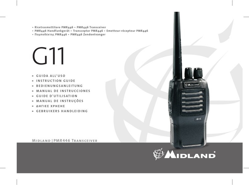
Midland G12 Manual

”G U I D AA L L‘ U S O
”I N S T R U C T I O NG U I D E
”B E D I E N U N G S A N L E I T U N G
”M A N U A LD EI N S T R U C C I O N E S
”G U I D ED ' U T I L I S AT I O N
”M A N U A LD EI N S T R U Ç Õ E S
” Δ Η Γ Ι Ε Σ Χ Ρ Η Σ Η Σ
”G E B R U I K E R SH A N D L E I D I N G
Midland|PMR446 Transceiver
ÿRicetrasmettitorePMR446ÿPMR446Transceiver
ÿPMR446 Handfunkgerät ÿTransceptor PMR446 ÿEmetteur-récepteurPMR446
ÿ Ποποδέκτη PMR446 ÿ PMR446 Zendontvanger
G12

1
English
In this manual…
1 Introduction 3
2 Safety First 4
2.1 Conventions and Symbols in this manual 4
2.2 Warning notes 4
2.3 Service 5
3Parts description 6
3.1 Description of parts and of the commands 6
3.2 Symbols on the display 8
4 Preparing to use 9
4.1 Fixing/removing the belt clip 9
4.2 Installing/removing the batteries 9
4.3 Recharging the batteries 10
4.4 Proper use of rechargeable batteries 11
5 Standard operations 12
5.1 Turning on/off 12
5.2 Back light of the display 12
5.3 Checking the remain battery charge 12
5.4 Volume regulation 13
5.5 Selection of the operational channel 13
5.6 Reception and transmission 14
5.7 Operationalmodes(openorrestrictedtrafc) 15
5.8 Monitor function 16
5.9 Selection of transmission power 16
5.10 Keypad lock 17
5.11 Audio call function 17
5.12 Enabling/disabling keypad tones 17
5.13 Enabling/disabling roger beep 17
6 Functions of the MENU button 18
6.1 Selection of melody call 19
6.2 VOX Mode 19
6.3 Scanning of favourite channels 21
6.4 Vibration alert 22
6.5 Dual Watch 22
6.6 Transmission lock when channel is busy 22
6.7 Compander 22
6.8
Timeout timer 23
6.9 Forced reception time 23
7 Programming frequencies and CTCSS/DCS codes 24
7.1 Programming modes 24
8 Cleaning and maintenance of your radio 25
8.1 Cleaning the radio 25
8.2 Contacts of desk battery charger 25
8.3 Connectors 25
9Troubleshooting 26
9.1 Troubleshooting table 26
9.2 Reset 28

2
English
10Technicalspecication 29
11 Frequencies and codes tables 30
11.1 Equivalent number of reference
MIDLAND G12 - PMR446 channels radio frequencies 30
11.2 Equivalence of reference number of
MIDLAND G12- frequencies of CTCSS tones 30
11.3 Equivalence of reference number
MIDLAND G12 - DCS codes 31

3
English
1 Introduction
MIDLAND G12 is a high-quality handheld transceiver. Its robust and
reliable design makes it ideally suitable for professional use and free
timepleasure.It’ssuitableforinniteapplications:frombuildingsites,
shoppingcentres,hotels,theatres,tradefairs,discos,seasideresorts
etc.Moreoverit’sidealfortrailblazing,sport,communicationamong
vehicles,gameseldsandmuchmore.MIDLAND G12 enables you
to communicate on all channels of the PMR446 band using a great
number of functions. The main features of your transceiver are the
following:
•A total of 16 channels - 8 channels for open trafc and an
additional 8 with CTCSS (Continuous Tone Code Squelch
System)
• Large, automatically backlit LCD display - makes using the
device easier, even in poor lighting condition, by constantly
displaying parameters and settings
• Status LED - shows the device’s current operation status
(reception,stand-byortransmission)
• Automatic background noise suppressor (squelch) - when
the device is in reception mode waiting for calls (standby), it
automatically eliminates the annoying background noise
• Automatic power saver - when in standby mode it enables
energy saving thus lengthening battery life
• CTCSS/DCS codes - restrict communication to only those users
who have set the same code of yours
• Channel scan - automatically searches radio signals on your
favourite channels
• Dual Watch -allowsmonitoringofradiotrafcontwochannelsof
your choice
• VOX (Voice Operated eXchange) - activates transmission just
with your voice without the need to press the PTT button. When
usedinconjunctionwithoptionalaudioaccessories,thisfeature
enables the user to operate completely hands-free
• Call button - puts the transceiver into transmission mode,
generating one of the 10 audio call tones of your choice.
• Vibrating alert - used in conjunction with the call button it enables
the sending/receiving of silent calls
• High/low power selection - enables two levels of transmission
power(reducedforshort-distancecommunication),savingenergy
and extending battery life
• Reception signal indicator - indicates signal strength by the
number of LCD bars
• Battery charge indicator - indicates remaining battery charge
• Keypad lock - avoids change of settings by the accidental
pressing of buttons
• Can be also powered by 3 AAbatteries - the type of AAbatteries
(notincluded)usedcaneitherberechargeableoralkaline,giving
totalexibilityandeconomyofuse
• Speaker and microphone/battery charger connector
(SPK, MIC/CHG) - these connectors enable the use of various
microphone accessories, as well as the use of an optional
standard wall battery charger
• Belt clip - for a more convenient use
2The manufacturer, in its effort to constantly improve product
quality, reserves the right to change characteristics and features
without prior notice.

4
English
2 Safety First
2.1 Conventions and Symbols in this manual
For ease and convenience of use, this manual uses symbols to
highlight,practicaladviceandcriticaloressentialinformation.
! This symbol marks ‘caution’. These special notices - relating
to technical information, danger, safety, cautionary advices
and/or information - are of the utmost importance. You should
pay careful attention to this type of information to avoid
possible damage to your equipment and to avoid potential
danger to yourself or other people.
2This symbol marks a ‘note’. Notes are hints or tips offering
additional information you are advised to follow to get the best
performance out of the device.
Important words sentences are underlined.
2.2 Warning notes
! Be careful to follow strictly all warnings in this chapter
2.2.a General
• Before using the transceiver, carefully read all instructions
contained in this manual in the order in which they are written.
Cross-reference to paragraphs and chapters is provided for ease
of use only. After reading this manual keep it for future reference.
• Read and follow all warnings and instruction labels found on the
radio and its accessories.
• Always observe laws and regulations regarding the use of
transceivers,whichmaychangefromcountrytocountry.Where
prohibited,orinareaswheretheradiomaycauseinterferenceor
danger,turnoffyourradio.
• Do not use your transceiver if the antenna is damaged - although
theradioisprotected,thismayseriouslydamageitsR.F.power
stages.
• During transmission keep the antenna at least 2.5cm from your
head and body and maintain a distance from other electrical/
electronic devices. Your transceiver contains a radio transmitter.
Beawarethat,whenyoupressthePTT or CALLbutton,theradio
emitsradiofrequency(RF)energy.Ifyouusecardiacstimulators,
hearingaids,orothermedicaldevices,consultyourdoctororthe
manufacturer of the device to ensure the device is adequately
protected from RF energy. Your doctor will be able to suggest
ways of obtaining these information.
• Keep a tight grip on your radio to prevent falls and consequently
possible damage. Ensure the PTT or CALL button is not pressed
accidentally when you do not need to transmit. Do not hold the
transceiver by the antenna! This is a delicate part of the device
and it is vital for the proper functioning of the radio.
• Be aware of environmental conditions - although the transceiver
wasdesignedtooperateunderthemostsevereconditions,itis
important to avoid exposure to environments that are excessively
humid or dusty, or to temperatures outside the -20° to +55°
Celsiusrange.Alsoavoidexposuretodirectsunlight,jarring,and
excessive vibration.
• Beforeusingtheradio,ensurethatallprotectivecoversandparts
areinperfectoperatingcondition,inordertoensuremaximum
protection against humidity and atmospheric agents.
• Although this radio was designed to be used in extreme weather
conditions,avoidgettingitwetasmuchaspossibleanddonot
let any type of liquid fall on it. If the transceiver or one of the

5
English
accessoriesgetswet,dryitoffassoonaspossiblewithasoft,
clean cloth. If you feel that liquid may have penetrated the radio’s
housing,contactaservicecentreforacheck.
• Do not use the radio, its accessories, and/or substitute the
batteries in potentially explosive environments. A single spark
may cause an explosion.
• Do not take apart the radio or its accessories for any reason! The
equipment has already been calibrated for maximum performance
inthefactory.Onlyqualiedexpertsequippedwithspecializedtools
andworkinginauthorizedcentres,canhandlethetransceiver’s
precision mechanics and electronics. Unauthorized dismantling of
the transceiver will void the warranty. Any service operation must
be carried out only in an authorised centre. For further information
contact your local dealer.
• Use original accessories only; otherwise you may seriously
damage your handheld transceiver.
• Turn off the radio and unplug the power supply before cleaning it.
Forfurtherinformation,refertoChapter8.
2.2.b Batteries and chargers
• Beforeusing thebattery chargers,carefully readall notesand
cautions regarding this equipment.
• Donotshort-circuitthebatteryterminals:doingsomayresultin
re,burns,orexplosions.
• Never throw batteries into a re. Do not expose them to high
temperatures;doingsomaycauseresorexplosions.Becareful
to always follow local regulations (which may not be the same as
thoseofthecountryofyourhabitualresidence).
• Use only original rechargeable batteries and battery charger. Use
ofunapprovedaccessoriesmaycauseburns,res,orexplosions,
and may cause serious damage or injuries to people.
• Battery chargers should only be used indoors and with suitable
rechargeable batteries.
• Ensure your power supply conforms to the one required for your
batterycharger(ACadaptor).Ifyouareunsure,checkwithyour
vendor or your local electricity supplier.
• To avoid damaging the power cord of your battery charger,
connect it where it will not be stepped on and where nothing will
be placed on top of it. Insert the prongs into a socket that has
been grounded.
• Avoid shocks and excessive vibrations. Do not use the battery
chargerifithasbeenknocked,hadafallorappearsdamaged.In
this case immediately contact an authorized service centre.
• To reduce the risk of electrical shocks, disconnect the power
cable before performing cleaning or maintenance. Take hold of
theplug(notthecord!)whenremovingitfromthesocket.Use
of inappropriate extension cords may cause re or electrical
shocks.
• Do not expose the batteries directly to temperatures outside the
-20°C to +55°C range during storage. Do not charge them in
temperaturesoutsidethe+5to+55°Crange.
2.3 Service
You are advised to write down the serial number of your transceiver
in the space provided below. This number is found on a label sticker
inside the batteries compartment of the transceiver and will be useful
in the event of repair/servicing and/or loss and/or theft.
Serial number _______________________

6
English
3 Parts description
3.1 Description of parts and of the
commands
Refer to the following pictures to locate the
variouspartsandgetfamiliarwiththedevice:
15
16
9
17
14
1
2
12
3
4
6
7
11
10
5
9
8
13

7
English
[1] Antenna(cannotbedetached)-receivesandtransmitradio
signals.
[2] ON/OFF/VOLUME knob - turns the equipment on/off and
adjusts audio volume reception.
[3] LCD display - the liquid crystal display constantly displays
operating status of the device and functions currently in use.
For further details see paragraph 3.2.
[4] SCAN/MON button - enables memory scanning. When kept
pressed it enables the monitor function.
[5] MENU button - enables the access to program functions and
settings.
[6] The – button-setsvariousfunctions,forexampleitreduces
the number of the currently tuned radio channel. If this
buttonispressedwhilethedeviceisbeingswitchedon,the
conrmationsoundwhichisaudiblewhenabuttonispressed
is enabled/disabled.
[7] Integrated microphone - Here is where the microphone is
housed.
[8] Integrated speaker - Here is where the speaker is housed.
[9] The + button -setsvariousfunctions,forexampleitincreases
the number of the currently tuned radio channel. If this button
ispressedwhilethedeviceisbeingswitchedon,theroger
sound is enabled/disabled.
[10] CALL/LOCK button-whenbrieypresseditsendsanaudio
call of your chosen melody on the currently selected channel.
If it is kept pressed blocks/unblocks the keypad.
[11] Push To Talk PTT button - press this button to switch to
transmission.
[12] Status LED - shows the operative state of the device in the
followingway:
• Waiting for calls (standby)-ashesevery4/5seconds
(ref.par.5.6.a)
• Receiving signals -asheseverysecond(ref.par.5.6.b)
• Transmission-constantlylit(ref.par.5.6.c)
[13] Connectors SPK, MIC/CHG (on the side of the device
under the rubber protection) - connectors for speaker and
externalmicrophone.Theirpurpose,whenusedtogether,is
for connecting optional accessories, such as microphones,
earphones etc. Also, the MIC CHG socket is used for
connecting the optional wall battery charger.
[14] Removable belt clip - for the convenience of attaching the
device to the belt.
[15] Batteries compartment cover - this compartment holds 3 AA
batteries(optional)-rechargeable1.2VNiMH,oralkaline1.5V
(nonrechargeable)-tosupplyyourhandheldtransceiver.The
compartment can also house the battery pack that comes with
the desktop charger supplied.
[16] Contact points for charging batteries (on the rear of the
device) - used to connect to the desktop battery charger
supplied.
[17] Battery cover clasp - holds the battery cover in place.

8
English
3.2 Symbols on the display
The liquid crystal display of your PMR446 transceiver constantly
displays the operating status of the device and the function currently
inuse.Possiblesymbolsandtheirsettingaredescribedbelow:
Symbol Meaning Description Ref.
Battery charge
level Shows remaining level of battery
charge. 5.3
Signal strength During reception the level of
signal strength is shown on the
basis of the number of bars
displayed. During broadcast all
barsash.
5.6.b
Radio channel
/multifunction Wheninstandby,thesethree
large digits show the channel
currently selected. During
programming they show
different parameters and their
values (e.g. = level of power
transmission).
5.5
Power Save It shows when power save is
active 5.6.a
Multifunction
indicator Wheninstandby,thesmall
digits to the right of the display
show the CTCSS tone or DCS
code currently set (e.g. =
toneCTCSSNum.16).During
transmission it shows different
parameters and their values
accordingly. For example
meansON(functionisactive)
and means OFF (function is
disabled).
5.7
Low power
transmission Lower power transmission is
selected. 5.9
Keypad locked Keypad is locked. 5.10
VOX VOX function is active (Voice
OperatedeXchange)-itenables
hands free use of your device.
6.2
Channel
scanning Channel scanning is taking
place(automaticsignalsearch)
on the preset channels.
6.3
Call vibrate Call vibration is active 6.4
Dual watch Dual Watch (quick search of
signalsontwochannels)is
active.
6.5
Timeout Timer Timeout Timer is active. 6.8
Programming The device is in programming
mode. 7.1

9
English
4 Preparing to use
4.1 Fixing/removing the
belt clip
The rear belt clip allows the user to
easily clip the transceiver to a belt.
However, it may be necessary to
remove the clip in order to make
radio maintenance or battery
substitution easier to carry out.
To remove the clip lift the release
lever and drag the clip upwards until
it comes free.
To fasten the clip to the device,
position it above the groove found
ofthebackofthetransceiver,then
drag it downwards until it locks into
place.
! Ensure the belt clip is correctly attached; otherwise the
transceiver may become unattached and accidentally fall.
4.2 Installing/removing the batteries
The transceiver is powered by 3 optional batteries AA type. There are
twobatteryoptionsavailable:
• Rechargeable 1.2V NiMH - available in various capacities (in
mAh).Higherbatterycapacityallowsforgreaterduty,butrequires
longer recharging time.
• Non-rechargeable 1.5V alkaline.
MIDLAND G12 can also be powered by a battery pack that ships
with the supplied desktop battery charger
2For installing/removing the batteries, it is not necessary to remove
the belt clip (procedure outlined in par. 4.1), however, this does
make it easier to access the batteries
! Do not install a combination of rechargeable and alkaline
batteries in your transceiver. Always use 3 AA batteries of
the same type, brand, and from the same stock. Always use
the same batteries, as a set in order to ensure their level of
charge is the same.
! If you are not using the transceiver for an extended period,
remove the batteries.
4.2.a Installing the AA batteries:
1) Carefully unhook the rear clasp by slightly raising it and
catchingthedepressionwithangernail,thenrotatingtheclasp
downwards.
2) Carefully lift the rear protective
cover from the battery
compartment and remove it.
3) Insertthebatteries(rechargeable
or alkaline) in the battery
compartment, ensuring the
batteries are correctly oriented
in their polarity, as indicated
on the inside of the battery
compartment.
4) Carefullyinsertthecover’stabsintotheslotsatthetopofthe
battery compartment, and then slowly press the cover down
Lever
Groove
Slot

10
English
against the battery compartment until it is perfectly aligned with
the transceiver body.
5) Carefullyreturntheclaspontotheprotectivecover,pressinguntil
it clicks into place.
! Ensure you have placed the batteries with the correct polarity
and that you have properly closed the battery compartment
cover.
4.2.b To remove the batteries:
1) Followsteps1and2asoutlinedabove.
2) Removethebatteriesfromtheradio.
3) Followsteps4and5asoutlinedabove.
4.2.c To install the battery pack
1) Followsteps1and2ofparagraph4.2.a.
2) Placethebatterypackwiththelabelandthecontactsfacingyou
3) Carryoutsteps4and5ofparagraph4.2.a.
4.3 Recharging the batteries
Two types of battery chargers are available. Each one is able to
chargeNiMHbatterieswithoutremovingthemfromtheradio:
•Standard optional wall battery charger - this is the least
expensive and it is used with the AA batteries and the battery
packsupplied.Forfurtherdetails,refertopar.4.3.a.
•Desktop battery charger - for greater exibility of use the
transceiver is simply slotted inside the battery charger. It can only
be used with the battery pack . For details consult par. 4.3.b.
If the batteries are new it is necessary to charge them fully before
using them. For subsequent recharges please refer to par. 4.4.
2New batteries do not immediately allow for maximum duty, as
they must be “run in” through at least 3 complete cycles of charge/
discharge.
! Use the battery charger only if you have installed 3
rechargeable NiMH batteries. Never attempt to charge other
types of batteries (particularly alkaline) - doing so may cause
explosion and/or personal injury.
! Do not overcharge the batteries! The charging process does
not stop automatically even when the batteries have been
fully charged. Do not forget therefore, to remove the charger
from the transceiver as soon as the batteries are charged.
! In order to get the best out of your batteries for subsequent
recharges consult par 4.4. Also consult the warning relative
to the use of batteries in par. 2.2.b.
4.3.a Standard optional wall battery charger
1) Ensuretheradioisturned off(itmust remainoffforthe entire
periodofrecharge).
2) Carefullylifttherubberapontherightsideofthetransceiver,
slippingangernailintothecentreleftpart,androtatingittowards
theright,asindicatedinthegure.
3) Insertthe plug attheendofthebatterychargercableintothe
MIC/CHGsocket(thelower,smallerone),andthenconnectthe
battery charger to an AC power source.
4) Oncethebatteriesarecharged(seetableinthenextpagefor
charging times), disconnect the battery charger from the AC
power source, and then disconnect the transceiver from the
battery charger.
5) Returntherubberaptoitsplace.

11
English
! Donotforgettoreplacetherubberapaftercharging.
Battery capacity (mAh) Time (hours)
1.200 10
1.800 15
APPROXIMATETIMESFORACOMPLETERECHARGE
ACCORDINGTOTHETYPEOFBATTERYUSED
4.3.b Supplied desk top battery charger
1) Ensurethatthebattery packisinstalled(the charger doesnot
workwithAAtypeNiMHbatteries).
2) Ensurethattheradioisturnedoff(itmustremainturnedoffforthe
wholechargingcycle)
3) Insertthetransceiver,with thefrontfacingyouintothebattery
chargerslot,andthenconnectthebatterychargertoanACpower
source.Chargingwillbegin,andtheappropriateLEDindicatorwill
light up.
4) When charging is complete take out the transceiver from the
housing and unplug the battery charger from the mains.
The battery pack is 1800mAh and takes approximately 10 hours for
a full charge.
4.4 Proper use of rechargeable batteries
Whenpossible,rechargebatteriesonlywhenat least two of the icon
bars have disappeared (the remaining battery charge icon should
indicate ).Beawarethatchargingtimevariesinproportiontothe
amountofresidualchargeremaininginthebattery,therefore,when
onlytwobarsappearintheicon,thisindicatesyouwillrequireabout
66% of time indicated on the table in par. 4.3.a. This is particularly
important otherwise you risk undercharging or overcharging the
batteries.
Ifyouusethebatteriesproperly,youwillobtainatleast400cyclesof
charge/discharge at maximum duty.
2Rechargeable batteries lose their charge over time even if they
are not used (auto-discharge); this is normal. A NiMH (Nickel
Metal Hydrate) battery may lose 10 - 20% of its energy within a
few days.
4.4.a Memory effect
Rechargeable NiMH (Nickel-Metal-Hydrate) batteries are virtually
unaffected by the “memory effect”. This phenomenon is associated
with a drastic reduction of battery autonomy and is triggered if the
batteries are regularly charged before having lost at least 50-75% of
their power and/or they are not completely recharged. To avoid the
memoryeffect:
• When possible, recharge the batteries only when they are
completely discharged; i.e. when the battery indicator will be
ashing.
• Do not disconnect the battery charger before battery charging is
complete.
• Discharge and recharge your batteries completely at least twice a
month.
Inanycase,thebestsolutionforavoidingthememoryeffectisto
useinturntwobatterysets:whileoneinusethesparesetcanbe
fully charged.
Memory effect can be easily cancelled after 3-4 complete cycles of
charge/discharge.
2The memory effect should not be confused with the normal

12
English
battery life, which is 400 cycles of charge/discharge on average.
It is completely normal for operating duty to decrease when the
batteries have reached the end of their life; at this point, you will
need to substitute the battery set.
5 Standard operations
5.1 Turning on/off
To switch on the transceiver, turn the ON/OFF/VOLUME knob
clockwiseuntilyouhearitclick:theLCDdisplaywilllightupandyou
willhearabeep(acousticsignal).Ifthevibratingfunctionhasbeen
previously activated it will also vibrate for about one second (ref. par.
6.4).
2The LCD display backlighting will automatically turn off after
approx. ve seconds in order to save energy, though the display
itself will remain active.
Toturnoffthetransceiver,turntheknobcounter-clockwiseuntilyou
hear another click.
5.2 Back light of the display
Whenever you turn the device on and every time you press a
key (excluding PTT o CALL/LOCKkeys), the display backlight is
automaticallyswitchedonforaboutvesecondssoastoallowyou
toreadeveninpoorlightingconditions.Ifduringtheveseconds
youpressanotherkey,youextendthedurationofthebacklightby
anotherveseconds.
2The display backlight absorbs additional battery charge. For this
reason you are advised to make moderate use
5.3 Checking the remain battery charge
When the transceiver is on standby (waiting for call), the battery
charge indicator shows the remaining level of charge according to
thefollowingchart:

13
English
Indicator Meaning Notes
Full charge The symbol will show when batteries
are completely charged (e.g. Soon after
recharging)
2/3 of
charge
remaining
-
1/3 of
charge
remaining
Low level of remaining charge. It is
advisable to reduce consumption in
order to extend battery life and get the
most out of remaining charge.
Battery
completely
discharged
Insufcientchargetoallownormal
functioning of the device which will turn
itself off after a short period. Recharge
the batteries or change them with
another set.
2The remaining charge indicator does not update the reading
during charging or transmission.
2When the level of remaining charge is equal to or less than ,
the device gives a warning signal.
5.4 Volume regulation
Bring the ON/OFF/VOLUME knob to medium position. Once the
transceiverreceivesasignal,adjustthevolumetoacomfortablelevel.
Ifnosignalisreceived,usetheSCAN/MON button as described in
par. 5.8.
2Battery consumption is directly proportional to the audio level.
5.5 Selection of the operational channel
1) PressoncetheMENUbutton.Thedisplaywillstartashing.
2) Pressthe+or – button to scroll up or down the channel list till
you select the desired channel. To rapidly scroll channels keep
pressed the +or – buttonuntilyoureachthespecicchannel.
2Obviously the other party must select the same channel otherwise
you cannot establish contact
2You are advised to consult the following chapter to learn about
which channels to select
5.5.a Which channel should be selected?
Your MIDLAND G12has16channelsintotal(8+8)asshowninthe
followingtable.Pleasenotethat:
• Channels 1 to 8 are programmed with the eight frequencies of the
PMR446 band.
• Channels 9 to 16 are programmed with the same radio frequencies
as the ones from 1 to 8 (e.g. channel 9 has the same frequency as
channel1),withtheadditionhoweverofthetoneCTCSSNr.16.
Therefore,whentheyareselected,thedisplayshowsc16 after
the channel number.

14
English
Channel Frequency (MHz) CTCSS/DCS
1446.00625 NO
2446.01875 NO
3446.03125 NO
4446.04375 NO
5446.05625 NO
6446.06875 NO
7446.08125 NO
8446.09375 NO
9446.00625 CTCSS Nr. 16
10 446.01875 CTCSS Nr. 16
11 446.03125 CTCSS Nr. 16
12 446.04375 CTCSS Nr. 16
13 446.05625 CTCSS Nr. 16
14 446.06875 CTCSS Nr. 16
15 446.08125 CTCSS Nr. 16
16 446.09375 CTCSS Nr. 16
If you are communicating with a device of a different manufacturer
you are advised to use one of the rst eight channels so as to
guarantee maximum compatibility. Choose obviously the channel
that seems the less busy.
However,iftheotherpartyisalsoequippedwithMIDLAND G12 (or
anotherdeviceequippedwithCTCSStones),youcanchooseany
channel. Should all of the eight PMR446 frequencies be busy in your
areathenyoucanchooseachannel(theleastbusy)from9to16so
that the CTCSS only transmits communication from other members
of your group. For further details on CTCSS consult par. 5.7.
5.6 Reception and transmission
Duringtransmissionandreception,ensuretheantennaisasvertical
as possible and free from obstacles in the direction of your party to
get the best radio signal.
2Reception and transmission mode described below is the
simplest and is the so-called “open trafc”. It is however possible
to operate, in a different way. Consult par. 5.7.
5.6.a Waiting for calls
When the PTTisnotpressed,theradioisinreceptionmodeandit
is ready to receive incoming communication on the currently tuned
channel(stand-by).
When no signals are received,thecircuitcalledsquelchmutesthe
audio of your device in order to cancel the annoying background
noise.Inthesecircumstances,thestatusLEDwillashevery4/5
seconds.
If you are not receiving communications and have not activated any
commands for at least 10 seconds, the icon will ash on the
display,indicatingthatthepowersaverfunctionhasbeenautomatically
activatedandthestatusLEDwillasheveryfourseconds.
5.6.b Reception
As soon as you receive a signal the squelch function which silences
the audio in the absence of signals will be automatically disabled
allowingyoutohearthemessagereceived.ThestatusLEDashes
morefrequently(onceabouteverysecond)andonthedisplaythe
icon shows the strength of the signal (the number of bars is
directlyproportionaltothestrengthofthesignal).
2If reception is broken because of weak signal try to use the monitor
function as described in par. 5.8.

15
English
5.6.c Transmission
1) Ensurethatnooneelseistalkingontheselectedchannel(consult
previousparagraph).
2) KeeppressedthePTT button. The status LED is constantly lit
indicating that you are transmitting. The icon of the display
ashesonceeverysecond.
3) Waitabriefmoment,andthenspeakinanormalvoice,intothe
transceiver’s microphone at a distance of approx. 5 cm.All stations
that are tuned on the same channel will hear your message.
4) Whenyouhavecompletedyourmessage,releasethePTTbutton:
The status LED is turned off and the icon disappears from
the display and the transceiver returns to reception.
2Radiocommunicationdoes notnormallyallow talking andreceiving
simultaneously. For this reason complete your messages within a
reasonable time. You will reduce battery consumption and you will
allow users to transmit in turn.
2Obviously, you can only talk with others who are tuned on your
same channel. However if you can hear someone but cannot
transmit to them it is possible that the other party is making use of
CTCSS tones or DCS codes. For further details consult par. 5.7.
5.7Operationalmodes(openorrestrictedtrafc)
MIDLAND G12canbeusedintwoways:
Mode Pre-set
on channels Notes
Opentrafc
(without
CTCSS/DCS)
From 1 to 8 It is the mode so far described
whichallowsmaximumexibility
with devices of other manufactures.
However,ifotherswhoarenot
part of your line of communication
use the channel you are using in
yourarea,youwillalsoheartheir
conversation.Opentrafcisnot
idealforprofessionalpurposes,as
communication which is not relevant
for you may distract you.
Restricted
trafc
(with
CTCSS/DCS)
From 9 to 16
(with CTCSS
Nr.16tone)
You and anyone else within your
line of communication can hear only
the conversations which use the
same CTCSS tone or DCS code
that you have previously set on all
the devices of the group. CTCSS
and DCS are a sort of access code
which restricts communication only
to devices which are tuned on your
frequency and have set your same
code.
2If you wish to change the CTCSS tone or the DCS code of a
channel programmed in restricted trafc mode follow the
procedure set out in par. 7.1.

16
English
2 Restricted trafc mode does not guarantee privacy of
communication. Indeed, when using CTCSS/DCS, anyone
operating in open trafc mode can hear your conversation, they
cannot however take part, as they would not be heard from you.
2 Restricted trafc mode allows the use of the same radio frequency
by more than one group. For example, group A using CTCSS No.
16 tone will not hear conversations of group B who uses CTCSS
No. 20 tone and vice versa. However, if more than one user
transmits at the same time (e.g. one user from group A together
with one user from group B) on the same channel, there will be
interference. For this reason do not transmit if the radio signals
that the channel is busy even if you do not hear anything, waiting
instead for it to be free. If in doubt use the monitor function.
2If you have to use MIDLAND G12 in the proximity of electrical
equipment which generates electrical noise causing the squelch
to open frequently, it is advisable that you use the restricted trafc
mode.
5.8 Monitor function
Inordertolistenforextremelyweaksignals,asexplainedinpar.5.6.b,
thecircuitwhichsilencesaudioreception(squelch)isautomatically
turned off as soon as you receive a signal. However extremely poor
signalsmaynottriggerittoswitchoffand,asaconsequenceofthis,
you will hear broken conversation. In this case the function monitor
will help by disabling temporarily the squelch.
Moreover if the channel you are using has been programmed to
operateinrestrictedtrafc(ref.par.5.7),withthefunctionmonitor
you can temporarily disable CTCSS or DCS in order to monitor all
communication on the channel you are tuned in.
Inordertoactivatethefunctionmonitor,keeppresstheSCAN/MON
button for about three seconds until you hear a faint background
noise(oreventuallytheweaksignal).
Inordertodisablethemonitorfunction,repeattheoperation.
2Do not use the monitor function for too long as this will use up the
battery. The energy saving function (ref. par. 5.6.a) functions only
when the audio of your device is silenced (squelch enabled).
5.9 Selection of transmission power
The transmission phase absorbs the most energy. To extend the
batteryduty,youcanselectlowtransmissionpowerwhentransmitting
over short distances. When low transmission power is activated
willappearonthedisplay.Toselectlowtransmissionpower:
1) PresssixtimestheMENU button. The display shows Po (power of
transmission)followedbyLo(low)orHi(high)ashingaccording
to the pre-set values.
2) Pressbuttons+o –until you have selected the desired power.
3) PressPTTbuttontoexit,orwaitforfewseconds.Thedevicewill
go back to standby mode storing the new value set.
2If you are transmitting to someone who is nearby, try always low
power of transmission. In this way you will extend battery life
and reduce the risk of being heard by others outside your line of
communication.

17
English
5.10 Keypad lock
During normal use you can lock the transceiver’s keypad in order to
avoid accidental activation of any function.
To activate the keypad lock, hold down the CALL/LOCK button
for about three seconds until the symbol appears on the display
(bottom right). This will deactivate all buttons of the transceiver
except transmission (PTTbutton),call(CALL/LOCKbutton)andthe
monitor (SCAN/MONbutton-ref.par.5.8).Anyattempttoaccess
the disabled buttons while in this mode will cause an audio error
signal(lowtone).
To deactivate the keypad lock keep the CALL/LOCK button pressed
for about three seconds until the symbol disappears.
2It is not possible to lock the keypad when the device is scanning
or in Dual watch mode.
5.11 Audio call function
You can send an audio call on the selected channel. You can do this
bypressingbrieytheCALL/LOCK button. Your device will stay in
transmissionmodefortwoseconds,broadcastingthecall(toattract
theattentionoftheotherparty)andthenitautomaticallygoesback
to reception.
2During transmission of the call the speaker of your device will also
play the call melody as conrmation.
2You can select any of the 10 preset melodies.
2Audio call is a special feature of MIDLAND G12. For this reason it
is advisable to warn and check with the other party about it so that
unnecessary interferences may be avoided.
5.11.a Silent calls
If you are communicating with another MIDLAND G12,youcancarry
out silent calls! To do this, you enable the vibrating alert on your
device as described in par. 6.4. Once you have switched to vibrating
alert,everytimeyoureceiveacallfromanotherMIDLAND G12,your
device will alert you of the call by vibrating but it will remain silent.
2Silent call is a special feature which works only among MIDLAND
G12.
5.12 Enabling/disabling keypad tones
Keypad tones are emitted each time a button is pressed in order
to reduce the likelihood of accidentally pressing a button twice.
This option can be deactivated if you prefer the radio to be silent.
Toactivateordeactivatekeypadtones,carryoutthestepsoutlined
below:
1) Turnoffyourdevice.
2) Keep the – button pressed and turn the device back on. All
symbols on the display light up for about one second and you
hearabeepsoundofconrmation.
3) Whenthedisplaycomesbacktoitsnormalstatus,releasethe
– button. The keypad tones will be disabled.
5.13 Enabling/disabling roger beep
“Roger beep” is a brief tone which your radio gives out at the end of
every transmission as soon as you release the PTT button. This is
toavoidthatsaying‘roger’everytimeyounishtalking.Inorderto
enable/disabletherogerbeepdothefollowing:
1) Turnoffyourdevice.

18
English
2) Keep the button +pressed and turn your device back on. All
symbols on the display light up for about one second and you
hearabeepsoundofconrmation.
3) Whenthedisplaycomesbacktoitsnormalstatus,releasethe+.
The roger beep will be disabled.
2At point number 2, when roger beep is disabled it is given as a
two-tone signal, while its activation is signalled by a beep sound
followed by a two-tone signal.
6 Functions of the MENU button
With the MENU button you can set the basic functions of your
transceiveraccordingtoyourpreferences:selectionofchannel,VOX
mode,vibratingalert,scanningofchannels,etc.Inordertorecalland
settherequiredfunctiondoasfollows:
1) Press/scrolltheMENUbuttontoselectthedesiredfunctiontoset,
(e.g..Po(transmissionpower),asithasalreadybeendescribed
inpar.5.9).
2) Pressthe +or – button to set the currently selected function.
According to the case you can scroll different values on the
display (e.g. for transmission power you can choose between the
valuesLoorHi),oryoucanselectOn(functionenabled)orOff
(functiondisabled).
3) InordertomemorizethechosensettingpressthePTT button or
wait for a few seconds. The device will go back to standby mode
having memorized the chosen settings.
2After you have carried out step number 1), it is necessary to carry
out each successive operation within few seconds, or the device
will go back to standby mode conrming current settings.
2If, after you have carried out step 2) you wish to set another
function, go back to step 1 immediately.
The following table lists the functions which can be set according to
the number of times the MENU button is pressed.

19
English
Menu Function Display
1 Selection of the operational channel (Channel)
2 Selection of melody call CA
3 Settings of internal VOX I
4 Settings of external VOX E
5 Selection of channels to be scanned
6 Selection of transmission power Po
7 Vibration alert VIb
8 Dual Watch
9 Transmission lock when channel is busy bLo
10 Compander CPd
11 Timeout timer tot
12 Forced reception time PtY
6.1 Selection of melody call
Asdescribedinpar.5.11,abriefpressingoftheCALL/LOCK button
sends an audio call. To choose one of the 10 available melodies do
thefollowing:
1) PresstwicetheMENU button. The display shows CA(CALL)on
therightandaashingnumber(from 0 to 10)ontheleftwhich
refers to the melody currently in use.
2) Press the +or – button until you have selected the desired
melody: during the selection each selected melody is played
through the speaker.
3) PressthePTT button to escape or wait for a few seconds. The
device will go back to standby mode having memorised the
chosen setting.
2If at step 2 you select number 0, you will disable the call function
(briey pressing CALL/LOCK button will not carry out any
function).
6.2 VOX Mode
With VOX (Voice Operated eXchange) you can transmit without
pressinganybuttons:allyouneedtodoistalkintothemicrophone
at a short distance. If you rest the radio on a surface therefore you
can operate entirely hands free with VOX.
Moreover,byclippingthedevicetoyourbeltwiththeoptionalaudio
accessories (e.g. headphones with integrated microphone) which
connect to jacks SPK and MIC/CHG,youcanoperatehandsfree
even while you move around. This is the most suitable way for VOX
to work since your mouth will be at a constant distance from the
microphone.
You can enable/disable VOX and independently regulate its sensitivity
accordingtoitsuse:withtheoptionalaccessoriesorwhetheryou
use it by itself.
Table of contents
Languages:
Other Midland Transceiver manuals

Midland
Midland ALAN 100 PLUS B User manual

Midland
Midland G9 PRO User manual

Midland
Midland 13-881B User manual

Midland
Midland G18 Manual

Midland
Midland G7 Pro User manual

Midland
Midland 13-513 User manual

Midland
Midland G5 C User manual

Midland
Midland NEPTUNE 100 Manual

Midland
Midland G14 Manual

Midland
Midland 73-005 User manual

Midland
Midland Alan 78 Plus Multi B User manual

Midland
Midland CT 890 User manual

Midland
Midland 248 User manual

Midland
Midland CT3000 Manual

Midland
Midland 7001 User manual

Midland
Midland PMR446 TRANSCEIVER User manual

Midland
Midland Atlantic User manual

Midland
Midland G477 XT Manual

Midland
Midland ALAN 8001S EURO User manual

Midland
Midland 445 BT Manual