Midwest Mid-Tech Legacy 2000 User manual
Legacy 2000 System
USER GUIDE
®
PN: 98-05034

MID-TECH WARRANTY
MIDWEST TECHNOLOGIES ILLINOIS, LLC (herein called Mid-Tech) warrants to the original
purchaser that the product purchased shall be free of defect in material or workmanship. If the
product proves to be defective within the warranty period the purchaser must return, freight prepaid,
said product to Mid-Tech within thirty (30) days after such defect is discovered. Upon inspection and
examination by Mid-Tech, and at its option, Mid-Tech shall repair or replace, with a new or compa-
rable product. No product will be considered defective if it substantially fulfills the performance
specifications. Purchaser shall be responsible for all required maintenance service in accordance with
procedures outlined in Mid-Tech’s product operator manual or service bulletins.
All product(s) replaced or repaired under warranty shall carry the remainder of the warranty left on
the original purchase. All out of warranty product(s) serviced for fee or goodwill will have ninety
(90) days of warranty. The ninety (90) days shall begin on the date serviced by Mid-Tech.
Warranty periods for Mid-Tech products shall be:
Mid-Tech Legacy Consoles – 2 ½ years
Mid-Tech TASC Consoles – 2 ½ years
Mid-Tech ARC Consoles – 2 ½ years
Mid-Tech AgLogix Consoles – 2 ½ years
Mid-Tech Switch boxes – 2 ½ years (3, 5, 9 boom)
All other Mid-Tech products – 12 months (unless otherwise noted)
WARRANTY LIMITATIONS AND EXCLUSIONS
Mid-Tech will have no warranty obligation hereunder if the product is subjected to abuse, misuse,
improper or abnormal usage, acts of God, faulty installation, improper maintenance as outlined in
Mid-Tech’s product operator manual or service bulletins. Consumable items (items that are used
during normal operation) such as light bulbs, batteries, etc., and expendable items (items which wear
out in normal use) such as injection pump tubes, flow meter bearings, etc., will not be covered by
warranty. For products that come in direct contact with chemical, the specific recommendations
contained in Mid-Tech product bulletins must be adhered to, or this warranty is void.Any repairs or
alterations, other than those provided by Mid-Tech and/or its authorized representatives, will void the
warranty. Mid-Tech neither assumes nor authorizes anyone to assume for it any other obligation or
liability in connection with said product.
DISCLAIMER OF UNSTATED WARRANTY
The warranty printed above is the only warranty applicable to this purchase. Mid-Tech’s warranty
cannot be modified by any person or entity, including without limitation, any distributor or retailer
of Mid-Tech. All other warranties, express or implied, including but not limited to, the implied
warranties of merchantability and fitness for a particular purpose, are disclaimed.
LIMITATION OF LIABILITY
It is understood and agreed that Mid-Tech’s liability, whether in contract, in tort, under any warranty,
in negligence or otherwise, shall not exceed the return of the amount of the purchase price paid by
purchaser and under no circumstances shall Mid-Tech be liable for special, indirect or consequential
damages. In particular, Mid-Tech shall not be liable for damage to crops as the result of misuse or
negligence in the application of chemicals or operation of Mid-Tech products. The price stated for the
equipment is a consideration in limiting Mid-Tech’s liability. No action, regardless of form, arising
out of the transactions under this agreement may be brought by purchaser more than one year after
the cause of action has occurred.
FORM 19.1.2 09/07/00 REV-1

Switches
I
Legacy 2000
98-05034
R0
Introduction
Chapter 1 Introduction ------------------ 1-1
Chapter 2 Start-up ------------------------ 2-1
START-UP SEQUENCE ------------------------------ 2-1
Chapter 3 Operate ------------------------ 3-1
ENTERING THE OPERATE MODE ----------------- 3-1
PRODUCT MONITORING --------------------------- 3-1
PRODUCT CONTROL ------------------------------- 3-2
CHOOSING PRE-SELECTED RATES ----------- 3-2
MANUAL RATE CONTROL ------------------- 3-2
RESETTING ACCUMULATORS ---------------- 3-3
SPEED AND DISTANCE MONITORING ------------- 3-4
TOTAL DISTANCE RESET -------------------- 3-4
MANUAL SPEED ------------------------------ 3-4
AREA MONITORING ------------------------------- 3-5
AREA RESET FUNCTION --------------------- 3-6
DATA LOGGING ------------------------------------ 3-7
Chapter 4 Setup --------------------------- 4-1
FIELD SETUP --------------------------------------- 4-1
LIQUID MODE SETUP ------------------------ 4-2
PRESET APPLICATION RATES ---------- 4-2
FLOWMETER CAL. # SET -------------- 4-3
PRESSURE BASED SETUP --------------- 4-3
GRANULAR/NH3 SETUP --------------------- 4-6
PRESET APPLICATION RATES ---------- 4-6
GRANULAR CAL. # SET ---------------- 4-7
INITIAL SPREADER CONSTANT --------- 4-7
SEEDER SETUP -------------------------------- 4-8
PRESET APPLICATION RATES ---------- 4-8
SEEDER CAL # SET --------------------- 4-9
SPINNER MODE SETUP --------------------- 4-10
PRESET SPINNER RATES -------------- 4-10
SPINNER CAL # SET ------------------ 4-11
INJECTION PRIME/CALIBRATE FUNCTION 4-11
PRIME FUNCTION --------------------- 4-12
CALIBRATE FUNCTION ---------------- 4-13
MACHINE SETUP --------------------------------- 4-14
PRODUCT MODES -------------------------- 4-14
APPLICATION UNITS OF MEASURE -------- 4-15
VALVE/DRIVE TYPES ---------------------- 4-16
SERVO VALVE SETUP ----------------- 4-16
PWM VALVE SETUP ----------------- 4-20
INJECTION DRIVE SETUP ------------- 4-21
SYSTEM SETUP ----------------------------------- 4-22
SYSTEM UNITS ------------------------------ 4-22
KEY BEEP ---------------------------------- 4-23
Table of Contents

Legacy 2000
II
98-05034
R0
SHOW MODULES --------------------------- 4-23
LOG DATA ---------------------------------- 4-24
COM PORTS ------------------------------- 4-25
HARDWARE TEST --------------------------- 4-26
SOFTWARE RESET -------------------------- 4-26
TIME AND DATE ---------------------------- 4-27
SPEED SETUP ------------------------------------- 4-28
SPEED CALIBRATION ----------------------- 4-28
GSO SETUP -------------------------------- 4-29
BOOM SETUP ------------------------------------- 4-29
SWAT H SETUP ------------------------------------ 4-30
NUMBER OFSWATHS ---------------------- 4-30
BOOM ASSIGNMENT ------------------------ 4-30
GPS SPEED SETUP ------------------------------ 4-31
Chapter 5 Trouble Shooting ------------ 5-1
Chapter 6 Emergency Operations ---- 6-1
GROUND SPEED SENSOR FAILURE ---------------- 6-1
FLOW CONTROL VALVE FAILURE ---------------- 6-2
FLOWMETER/PRESSURE SENSOR FAILURE ------- 6-3
APPLICATION RATE SENSOR FAILURE ------------ 6-4
Appendix A System Diagram -----------A-1
SAMPLE SYSTEM DIAGRAM ---------------------- A-2
Appendix B - System Overview-------- B-1
System Components ---------------------- B-2
MODULES ----------------------------------------- B-2
CABLES AND HARNESSES ------------------------- B-4
LEGACY 2000 CONSOLE -------------------- B-4
POWER SPEED MODULE -------------------- B-4
SWITCH SENSE MODULE ------------------- B-5
PRODUCT CONTROL MODULE -------------- B-5
CAN EXTENSION CABLES ------------------ B-6
Appendix C - Glossary/Tables ---------- C-1
GLOSSARY ----------------------------------------- C-2
ENGLISH/METRIC CONVERSION ----------------- C-8
USEFUL FORMULAS ------------------------------- C-9
MISCELLANEOUS NOTES ------------------------C-10
CALIBRATION NUMBERS ------------------------C-10
NH3 DENSITY TABLE ---------------------------C-10
Index ------------------------------------------I-1
Mid-Tech, Auto-Range, & TASC are all registered trademarks of Midwest Technologies, Inc.

Switches
1-1
Legacy 2000
98-05034
R0
Introduction
Chapter 1 Introduction
Welcome to the Legacy 2000, the new genera-
tion of chemical control systems. The Legacy
2000 controls up to two different products,
automatically, manually, or under external control.
New technology allows the Legacy 2000 console to
communicate with remotely mounted control modules
through a single cable. These modules in turn control
and monitor the valves, sensors, pumps, etc. of the
system. Control modules can be “tapped” into the main
cable at any point, which means that they can be
mounted anywhere on the machine, near the compo-
nents that they are associated with. Using one cable to
connect the modules to the control console in the cab
eliminates the “rat’s nest” of cables running into the
cab from all over the vehicle.
The opeating program is contained on an SRAM card
inserted into the side of the console making it easy to
change or upgrade your program. (CAUTION: To
prevent damage to the program or the SRAM
Card, the console must be powered down while
inserting or removing the card)
This User Guide provides you with the basic
information needed to set up and operate the
MID-TECH®Legacy 2000 control system.
Actual procedures may vary, depending on the
configuration of your system.
When you see "Mitch", he is pointing out special
information that you should be aware of, regarding
safety, preventing equipment damage, an easier way to
perform an operation, etc..
A brief description of the console control buttons and
the icons that appear on the display are described at the
edges of the pages in Chapter 3 (Operate functions)
and Chapter 4 (Setup Functions)
The topics are presented with the most often used
information located toward the front of the guide.
HOW TO USE THIS MANUAL
Mid-T
Mid-T
ech
ech
Mid-T
Mid-T
ech
ech

Legacy 2000
1-2
98-05034
R0
Following is a listing of the chapters in this manual,
along with a brief description of the information found
in each chapter.
Chapter 1 - “Introduction” - A brief overview of the
User Guide.
Chapter 2 - “Start-up” - Describes the system start-up
sequence followed when powered on.
Chapter 3 - “Operation” - Describes how to control
the application process.
Chapter 4 - “Setup” - Takes you through the calibra-
tion of each sensor providing input to the system
and the entering of other necessary information.
Chapter 5 - “Trouble Shooting” - Lists possible
causes and remedies for the error messages that
may appear on the display.
Chapter 6 - “Emergency Operation” - Suggests ways
to operate, under reduced accuracy, in the event
of a major fault.
Appendix A - “Sample System Diagram.”
Appendix B - “System Components” - Describes the
major components of the Legacy 2000 system and
their individual functions.
Appendix C - Glossary/Tables
Back Cover - Quick Start/Quick Set Up Guides
2-1
Legacy 2000
98-05034
R0
Start-up
Sequence
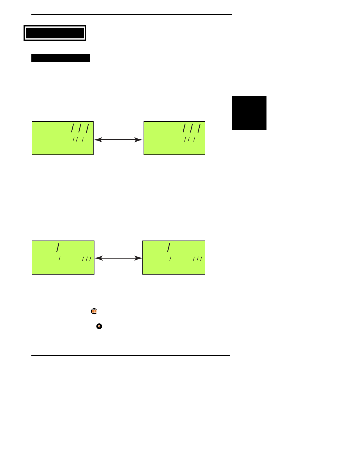
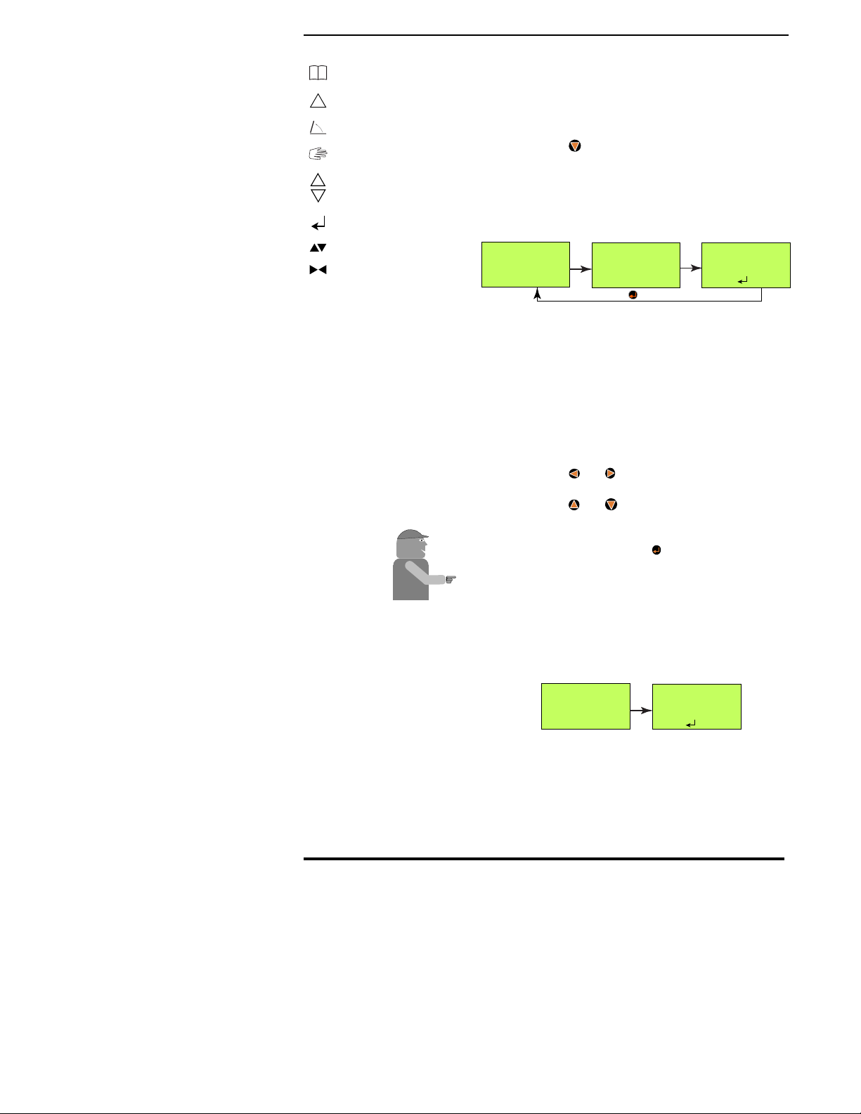
START-UP SEQUENCE
The Legacy system monitors the accessory
position of the ignition switch. When the
ignition switch is turned on the Legacy system
begins its start-up sequence. The console will alternate
between the two screens shown in Fig. 2-1 while it is
performing its system check.
During the system check each module (Console, PSM,
SSM, PCM) is verified to make sure nothing has
changed since the system was last powered up. If any
descrepancies are found the console asks for user
input to verify the module information.
Once the system check is complete the screens shown
in Fig. 2- 2 appear and three beeps are heard.
At this point the operator can:
•Press the Setup button ( ) to make any necessary
system setup changes to the Legacy system
•Press the Operate button ( ) to go directly to the
operate mode.
09:42
02/18/2000
PRESS OPERATE OR
09:42
02/18/2000
SETUP TO BEGIN
Alternate
Fig. 2-2. System Ready Screens
Chapter 2 Start-up
Fig. 2-1. Legacy System Check Screens
L2000
VER 00.01D
MID-TECH CONTROL
L2000
VER 00.01D
WELCOME TO
Alternate

Legacy 2000
2-2
98-05034
R0
This page left blank intentionally

3-1
Legacy 2000
98-05034
R0
Operate
Functions
2
1
Operate
Setup
Manual
Enter
Right
Left
Product 1
Product 2
Speed
Decrease
Increase
Area
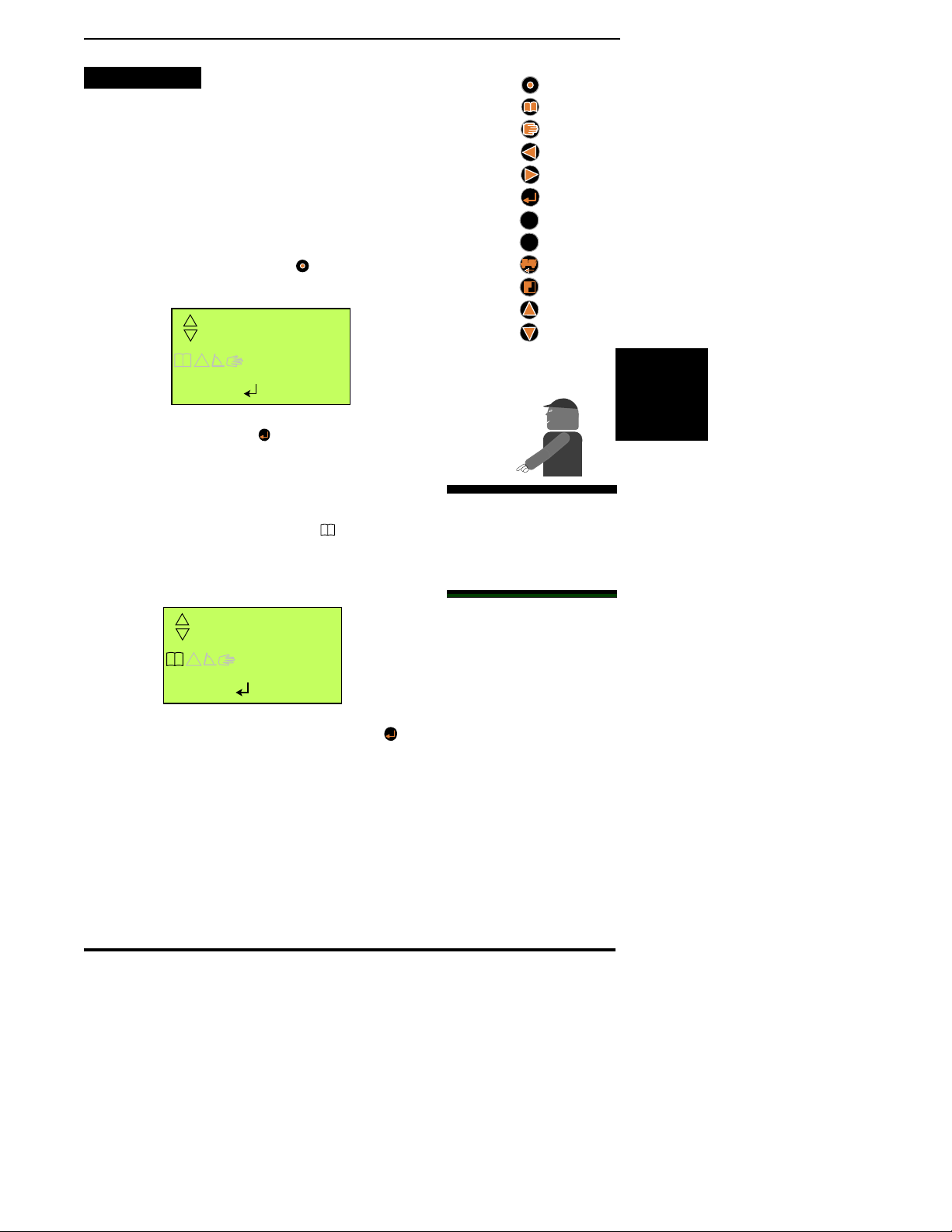
This chapter discusses the various “Operate”
screens that allow the operator to monitor and
control the application process.
ENTERING THE OPERATE MODE
Press to enter the “Operate”mode. The screen
shown in Fig. 3-1 appears. There are several
icons that may appear on the screen to provide
information to the operator. These icons are explained
in the corner of the even numbered pages.
PRODUCT MONITORING
Figures 3-1 through 3-4 give examples of the
types of information provided by some of the
different screens. The screen shown in Fig. 3-1
is the “Product Status OFF”screen, the first of several
“Product Information”screens. Pressing turns the
product ON, changing the
1
from red to green
indicating that the product is turned ON, and taking
you to the “Product Status ON”screen (Fig. 3-2).
Pressing
1
at this point causes the display to alternate
between Fig. 3-2 (Product ON) and Fig. 3-3 (Total
12.5
12.2MPH
P1 G/Ac
!
P2 OFF
Product 1
Screen
Current Product 1
Application rate
Application being
measured in gallons
per acre.
Product 2
Status
Current
ground
speed Fig. 3-2 Product Status ON
Can use and to change to
another pre-selected rate (A - E)
Chapter 3 Operate
Most examples in this User
Guide will use Product 1
screens and US units of
measure. Screen displays
will change accordingly
when monitoring Product 2
or using metric units.
Mid-T
ech
OFF
12.2MPH
P1 G/Ac
!
P2 OFF
Product 1
Screen
Product turned OFF
Application being
measured in
gallons
Product 2
Status
Current
ground
speed Fig. 3-1 Product Status OFF
Legacy 2000
3-2
98-05034
R0
!
Logging On
System Error
Not Used
Manual Mode
Control Active
Use Enter Key
Use Inc/Dec
Use Left/Right
Applied).
While in the “Product OFF”and “Product ON”screens
(Figs. 3-1 & 3-2) the and buttons can be used to
select the information to be displayed on the third line
of the display, as shown in Fig. 3-4.
Pressing
2
gives the operator the same set of screens,
displaying information about product 2, with Product 1
being monitored in the background.
PRODUCT CONTROL
CHOOSING PRE-SELECTED RATES
While in the “Product Off”or “Product ON”
screens (Figs. 3-1 & 3-2) the and
buttons can be used to step through the
application rates (A - E) preset in the “Field Setup”
routine. When the desired rate is being displayed, wait
for about 3 seconds. The selected rate will be locked in
and the display will revert back to the previous screen.
The selected rate is now the control rate.
MANUAL RATE CONTROL
The application rate of each product can be
controlled manually, using the “Manual Mode”,
from either the “Product ON”or “Product OFF”
screens. To enter “Manual Mode”select the desired
product and press . The screen shown in Fig. 3-5 is
displayed and the associated control valve “holds”in
its present position (closed if product is turned OFF or
12.2MPH
P1 Vol Gal
12.5
!
22AC
Fig. 3-3 - Total Applied
Product being
Displayed
Current
Speed
Amount of product
that has been applied
Units of
measure
Area Treated
0RPM P2 OFF
P1 G/Ac
12.5
!
12.2MPH
P1 G/Ac
12.5
!
22AC
12.2MPH
P1 G/Ac
12.5
!
P2 11.9
Current Speed Product 2 Status
Product 1 Area covered
Fig. 3-4 - Third Line Display
RPM Monitor

3-3
Legacy 2000
98-05034
R0
Operate
Functions
2
1
Operate
Setup
Manual
Enter
Right
Left
Product 1
Product 2
Speed
Decrease
Increase
Area
at the current rate if the product is turned on) and can
only be changed using the and buttons, overrid-
ing any programmed rate or external variable rate
command. When “Manual Mode”is turned off, control
of the application rate returns to the previous input
source.
Each product works independently meaning one or
both products can be under manual control but only the
selected product will be affected by the and
buttons at any one time.
To return to automatic control select the desired
product (1 or 2) and press again. The “Manual
Mode”symbol on the display is turned off indicating
that the product is back under automatic control.
RESETTING ACCUMULATORS
The “Total Applied”accumulators for each
product can be reset independently, with the
product turned ON or OFF. Just display the
“Total Applied”screen (Fig. 3-3) for the desired
product and press . The confirmation message shown
in Fig. 3-6 appears in the third line of the display.
Press to reset the accumulator to zero.
Mid-T
ech
CAUTION: EXTREME
CARE MUST BE USED
WHEN OPERATING IN
“MANUAL MODE”. The
longer the and
buttons are held down the
faster the rate at which the
valve moves. This means
that the application rate
can change drastically in a
short amount of time
causing a severe over or
under application.
12.2MPH
P1 G/Ac
12.5
!
22AC
Indicates product 1
under manual control.
Fig. 3-5 Manual Mode
CLEAR?
Fig. 3-6 Clear Alert
Legacy 2000
3-4
98-05034
R0
!
Logging On
System Error
Not Used
Manual Mode
Control Active
Use Enter Key
Use Inc/Dec
Use Left/Right
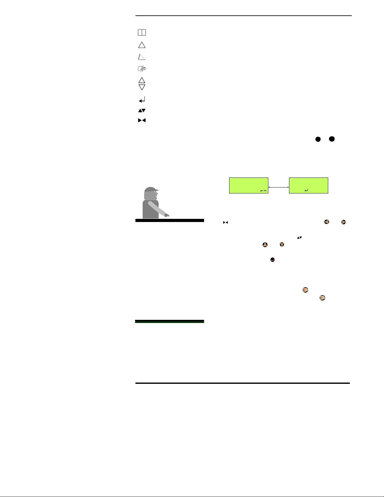
SPEED AND DISTANCE MONITORING
While in the “Operate Mode”pressing
accesses the “Speed/Distance”function. The
screens used in this function are shown in Fig.
3-7. The first screen that appears is screen “A” which
indicates the current vehicle speed with “Product 1 and
2” status alternating in the lower left corner. Pressing
now alternates the display between screen “A” and
screen “B” which indicates the total distance traveled.
To exit the “Speed/Distance”function press any other
function button.
TOTAL DISTANCE RESET
To reset the Total Distance accumulator go to
screen “B” of Fig. 3-7 and press . This takes
you to screen “D” with the alert at the bottom of
the display. To reset the accumulator press . To exit
the “Total Distance Reset”function without resetting
the accumulator press any other function button.
MANUAL SPEED
The Legacy 2000 has a “Manual Speed”function
that allows the operator to manually input a
simulated speed which overrides the actual
vehicle ground speed. This feature can be used to
perform static tests on the system or in an emergency
situation such as the failure of the vehicle speed
sensor.
SPEED
TOTAL DISTANCE
Alternates
between
Decrease
Resets the
accumulated distance
15.1
P1 RATE 10.0
MPH
!
153.13
MILES
!
20.3
MPH
!
153.13
CLEAR?
MILES
!
Manual
A
B
C
D
P2 RATE OFF
P2 RATE OFF
Fig. 3-7 Speed/Distance Screens

3-5
Legacy 2000
98-05034
R0
Operate
Functions
2
1
Operate
Setup
Manual
Enter
Right
Left
Product 1
Product 2
Speed
Decrease
Increase
Area
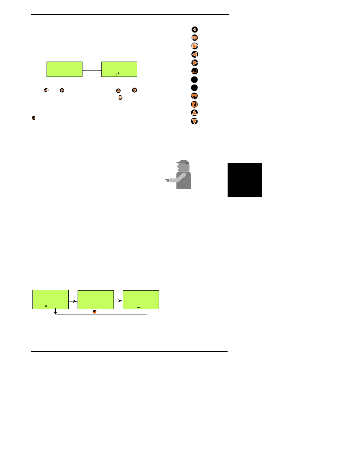
To switch to Manual Speed press from Screen “A”
in Fig. 3-7 taking you to screen “C” which is similar
except for the symbol indicating that you are
operating under Manual Speed control. While in
screen “C” the operator can use the and buttons to
adjust the speed being simulated by the system.
Pressing again turns the “Manual Speed”function
off and the speed control reverts to the previous input
source.
The Manual Speed selected is held in the console, even
when the feature is turned off, until the console is
powered OFF. The Manual Speed value then defaults
back to 5.0 MPH.
AREA MONITORING
To monitor the Total Area Accumulation of the
individual products and swaths press which
presents the screen shown in Fig. 3-8. Continu-
ing to press and release cycles the display through
the following screens:
•The total accumulated area for each active product
•The total accumulated area for each active Swath
•The swath width for each active swath
As each screen is being displayed the third line of the
screen continuously cycles through:
•P1 RATE
•P2 RATE
•Current Vehicle Speed
Press any other function to exit the “Area Display”
screen.
49.6
P2 RATE OFF
P1 AREA AC
!
Fig. 3-8 Area Display

Legacy 2000
3-6
98-05034
R0
!
Logging On
System Error
Not Used
Manual Mode
Control Active
Use Enter Key
Use Inc/Dec
Use Left/Right
AREA RESET FUNCTION
Each area accumulator can be reset individually
or all can be reset at the same time. When
resetting a Product Area accumulator the
product must be turned OFF. Select the screen
displaying the accumulator (Product or Swath) that you
want to reset. Press to take you to the screen shown
in Fig. 3-9. (The information displayed on the center
line will vary depending on which accumulator you
have selected.) To reset the selected accumulator press
. To exit without resetting press any other function
button.
To reset all area accumulators at the same time press
from the screen in Fig. 3-9 taking you to the screen
in Fig. 3-10. Press to reset all area accumulators. To
exit without resetting press any other function button.
49.6
CLEAR?
S2 AREA AC
!
Fig. 3-9 - Area Reset Screen
49.6
CLEAR ALL?
S2 AREA AC
!
Fig. 3-10 Area clear all Screen
Mid-T
Mid-T
ech
CAUTION: When
performing a “Reset All”
on the Area accumulators.
even the accumulators for
active products will be
reset.
3-7
Legacy 2000
98-05034
R0
Operate
Functions
2
1
Operate
Setup
Manual
Enter
Right
Left
Product 1
Product 2
Speed
Decrease
Increase
Area
DATA LOGGING
The Legacy 2000 can log operational data to
either an external recording device, connected
to the COM 1 or COM 2 ports, or to the
SRAM Card (See caution at side) in the Legacy
console. To do this the Logging Function must first be
configured as described in Chapter 4 under “Log
Data”.
To initiate Data Logging hold the button down for
three seconds. The Logging Control Screen shown in
Fig. 3-11 will appear. Press to start the logging
process. Pressing any other button will take you out of
the Logging Control Screen without making any
changes.
With logging active the logging icon ( ) will appear
on all screens.
The same procedure is used to stop logging except the
screen will look like the one in Fig. 3-12. When is
pressed logging stops and the logging icon disappears
from the screen.
LOG
PRESS
STOPPED
!
TO START
Fig. 3-11 - Starting Logging
LOG
PRESS
STARTED
!
TO STOP
Fig. 3-12 Stopping Logging
CAUTION: Always make
sure the Legacy console is
powered down before
inserting or removing the
SRAM card.
Mid-T
ech

Legacy 2000
3-8
98-05034
R0
!
Logging On
System Error
Not Used
Manual Mode
Control Active
Use Enter Key
Use Inc/Dec
Use Left/Right
This page left blank intentionally
4-1
Legacy 2000
98-05034
R0
Setup
Functions
2
1
Operate
Setup
Manual
Enter
Right
Left
Product 1
Product 2
Speed
Decrease
Increase
Area
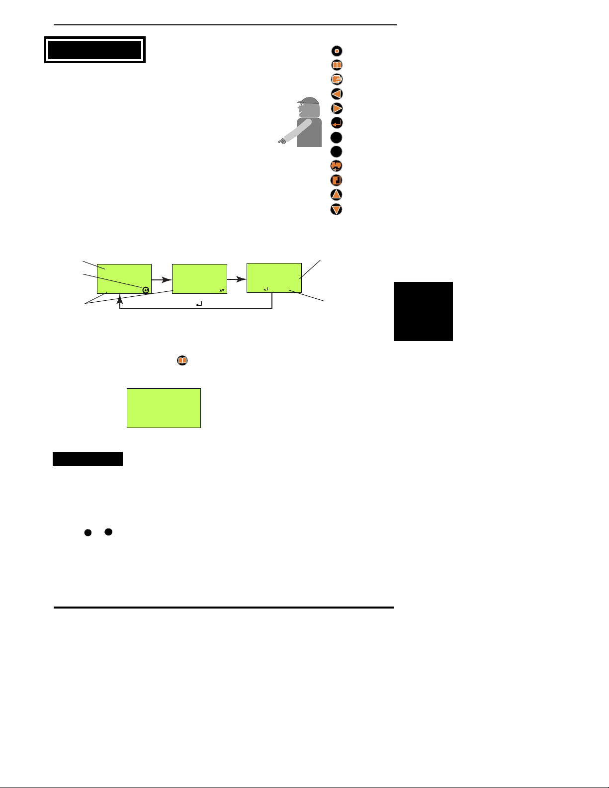
Before the Legacy system is used for chemical
application, important information must be
entered using the buttons on the face of the
console. The icons for these control buttons, and their
functions, are shown to the right.
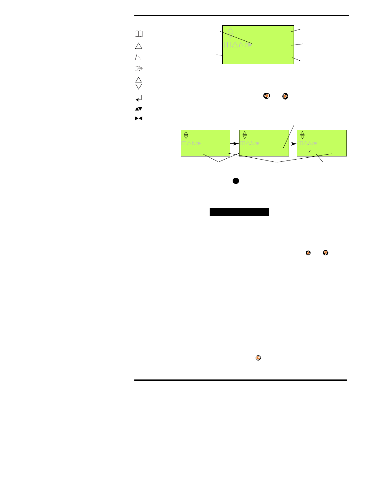
NOTE: Always read and follow the prompts and
messages on the screen carefully. The first line
indicates the value currently being adjusted. The
second line indicates the function being set up,
instructions, or other information. The third line
provides information and instructions. The display may
cycle through several screens to provide all needed
information. See Fig. 4-1 for examples.
To enter the Setup mode press , taking you to the
“Main Setup”screen (fig. 4-2).
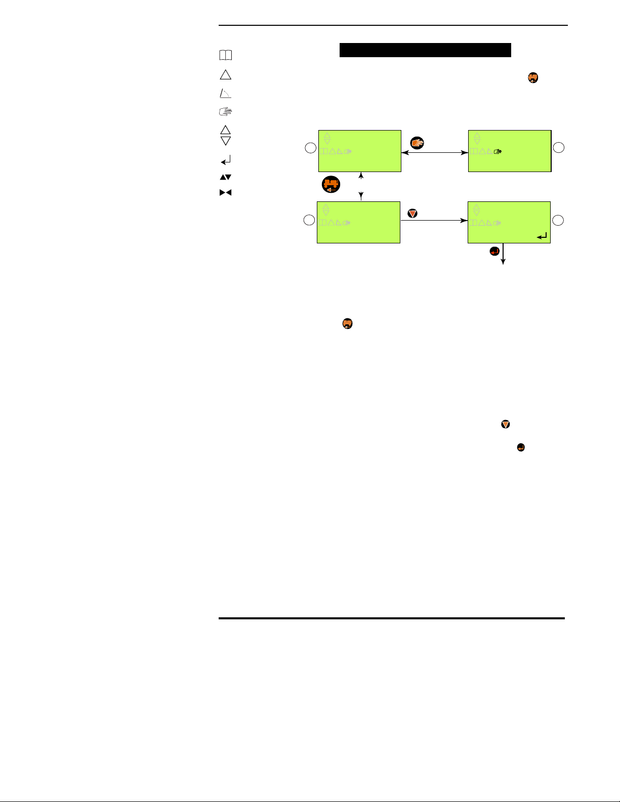
FIELD SETUP
The “Field Setup”functions allow you to adjust
values such as application rates, density,
calibration numbers, etc.. The “Field Setup”
mode is entered by pressing the desired product
button,
1
or
2
, from the Main Setup Screen (Fig. 4-2.
The “Product Application Modes”can be divided into
5 basic groups:
Mid-T
ech
PRESS TO CONT.
CLOSE
PRODUCT 1
VALVE RESPONSE
CLOSE
PRODUCT 1
CLOSE
PRODUCT 1
STATUS SW OFF
Cycles till is pressed
Fig. 4-1: Screen Cycling
Current
Value
Function
being
adjusted
Selects current
value and exits
Buttons
used to
adjust
Product affected
SETUP
CHOOSE FUNCTION
Fig. 4-2: Main Setup Screen
Chapter 4 Setup
Legacy 2000
4-2
98-05034
R0
!
Logging On
System Error
Not Used
Manual Mode
Control Active
Use Enter Key
Use Inc/Dec
Use Left/Right
•Liquid Mode (Page 4-2)
•Granular/NH3Mode (Page 4-6)
•Seeder Mode (Page 4-8)
•Spinner Mode (Page 4-10)
•Injection Mode (Page 4-11)
LIQUID MODE SETUP
Preset Application Rates
As many as five different rates (A - E) can be
preset into the Legacy 2000 Console.
With the desired “Product Application Mode”selected
under “Machine Setup”(Pg. 4-14) press
1
or
2
from
the “Main Setup”screen (Fig. 4-2) to enter the
appropriate setup function. (We are using “Liquid
Product 1”for this illustration.) This displays the
screens shown in Fig. 4-3. Which indicates that you are
setting Preset Rate “A”, it is being measured in
Gallons per Acre and the current value is 10.0 GPA.
The symbol indicates that you can use the and
buttons to select which digit of the Rate Value is
changed (The flashing digit). The symbol indicates
that you can use the and buttons to adjust the
value of the flashing digit. When the desired value has
been selected press the button to register the value
and advance to the Rate “B” preset screen. This
continues until all desired Preset Rates are set.
When setting the “Preset Rates”the button can be
used to move the decimal point. Each time is
pressed the decimal point moves one position to the
left until it disappears from the screen. The next press
of the button brings the decimal point back at the right
side of the screen.
If a flowmeter is used to control or monitor the
selected product continue to the next section. If only a
pressure sensor is involved go to the Pressure Calibra-
tion Section on page 4-3.
10.0
RATE A
P1 G/Ac Alternates
10.0
PRESS
P1 G/Ac
TO CONT.
Fig. 4-3 Setting preset Rates
Mid-T
Mid-T
ech
ech
When operating under
GPS control, Rate “C”
becomes the external,
“Variable Rate”. Rate “D”
becomes the Minimum
Allowable Rate and Rate
“E” the Maximum
Allowable Rate. Rates “A”
and “B” are preset rates,
which will override the
external rate command,
when either of them are
selected.
4-3
Legacy 2000
98-05034
R0
Setup
Functions
2
1
Operate
Setup
Manual
Enter
Right
Left
Product 1
Product 2
Speed
Decrease
Increase
Area
Flowmeter Cal. # Set
From the screen shown in Fig. 4-4 the initial
flowmeter calibration number can be set using
the same method as that for the Preset Rates
(Use and to select the digit and and to
adjust the value of the digit). Use the button to
adjust the position of the decimal point as described
on page 4-2. When the desired value is selected press
. If a pressure sensor is also used with this product
the next screen is Fig. 4-5. Otherwise the display exits
to the “Main Setup”screen (Fig. 4-2).
The flowmeter calibration number represents “Pulses/
Gallon”for US units and “Pulses/Liter”for metric
units. The flowmeter usually has a tag indicating the
“Initial Calibration Number”in Pulses/Gallon.
NOTE: Before starting actual application, a field test,
using water, should be done to verify the accuracy of
the Cal. #, and any necessary adjustments made. Use
the following formula to calculate a new Cal. #, if
necessary:
Pressure Based Setup
If a pressure sensor is used to control or monitor the
selected product, the low and high pressure values
of the sensor must be calibrated to match those of a
manual pressure gauge installed near the pressure
transducer. This process starts with the “Zero Set
Point”screen (Fig. 4-5).
From this screen we are setting the “Zero Pressure
Reference Point”for the console.
New Cal. # = MEASURED AMOUNT
INDICATED AMOUNT X OLD CAL. #
Mid-T
ech
0
SENSOR PSI
Cycles till is pressed
0
SENSOR PSI
0
SENSOR PSI
PRESS TO CONT.
HOLD TO SET ZERO POINT
Fig. 4-5 PSI Zero Point Set
Fig. 4-4 Flowmeter Cal. # Set
153.1
CHANGE CAL#
P1 CAL # Alternates
153.1
PRESS
P1 CAL #
TO CONT.
Legacy 2000
4-4
98-05034
R0
!
Logging On
System Error
Not Used
Manual Mode
Control Active
Use Enter Key
Use Inc/Dec
Use Left/Right
•The product pump must be turned OFF.
•At least one boom section of the associated swath must
be turned on to ensure that there is no pressure in the
boom. (It may be necessary to loosen a diaphragm check
valve to relieve all pressure.)
•Press and hold until the console beeps. The “Zero
Reference Point”is now set.
You should now see the screen sequence shown in Fig.
4-6, from which we set the “High Pressure Reference
Point”.
•Be sure to tighten any check valve loosened previously.
•The booms must be off (Master Switch OFF).
•The product pump must be turned ON.
•Slowly increase the engine RPM to adjust the pressure
reading on the manual pressure gauge to a maximum no
higher than the sensor’s specification.
•Set the pressure reading on the console to match that on
the manual pressure gauge.
•Use the and buttons to select the digit of the
display to be changed.
•Use the and buttons to adjust the selected
digit.
•When the console display has been set to match
the pressure gauge press .
NOTE: When using dual pressure sensors, both
sensors use the same Hi/Low pressure values.
The display reverts to the “Main Setup”screen (Fig. 4-
2) unless you are using a pressure sensor to control
product flow. In this case the screen shown in Fig 4-7
appears. This screen allows the operator to set the
“Nozzle Constant”into the console. The constant
should be taken from a nozzle chart for the particular
set of nozzles that you are using. Use the 10 MPH/30
PSI value (10KPH/2.0 Bar) for metric operation).
PRESS TO CONT.
30.0 30.0
REF PSI REF PSI
SET NOZZLE CONST
Fig. 4-7 Setting the Nozzle Constant
Fig. 4-6 High Set Point
0
SENSOR PSI
Cycles till is pressed
0
SENSOR PSI
0
SENSOR PSI
PRESS TO CONT.
PRESS MANUAL TO OPEN VALVE
Mid-T
Mid-T
ech
ech
Table of contents
Other Midwest Farm Equipment manuals


Popular Farm Equipment manuals by other brands

Blue Diamond
Blue Diamond 127006 Operation and maintenance manual

Game Winner
Game Winner FSGWSF1017 Assembly instructions

Zipper Mowers
Zipper Mowers ZI-MD500HST user manual

ROPA
ROPA Panther 2S Translation of the original operating manual

LELY
LELY Hibiscus 725 CD Classic Operator's manual

brielmaier
brielmaier Multi-Twister MT220B Translation of the original instructions

Spearhead
Spearhead TRIDENT 400 Operator's instruction manual

Arrowquip
Arrowquip EASY FLOW CATTLE ALLEY product manual

Rotomec
Rotomec HURRICANE H40-048 Operator's manual

GREAT PLAINS
GREAT PLAINS Turbo Max 1800TM Operator's manual

IAE
IAE CORN BINS Installation & maintenance manual

Dairy Tech
Dairy Tech Perfect Udder 10G owner's manual


