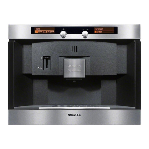
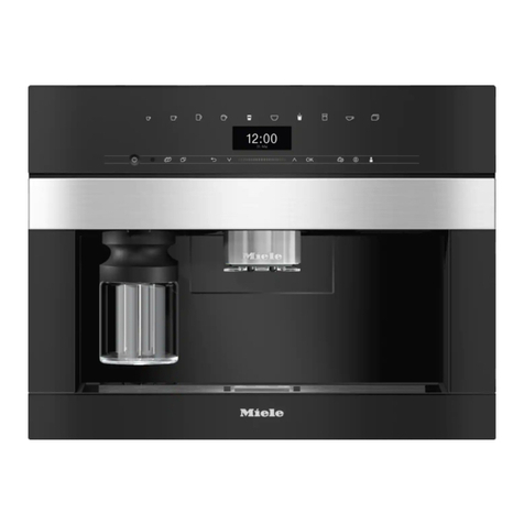
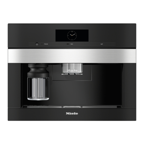
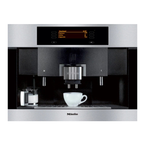
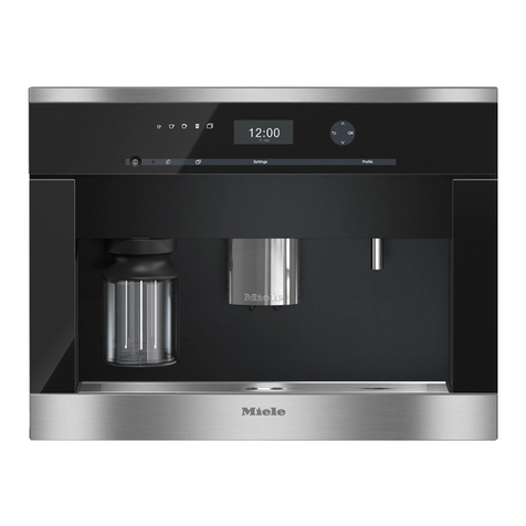
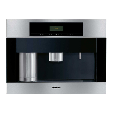
Miele CVA 2650 Manual

TECHNICAL INFORMATION
CVA 2650, CVA 2652, CVA 2660, and CVA 2662 Coffee Systems
© 2012 Miele USA

Technical Information
2
CVA 265x & CVA 266x
Table of Contents
AWarning and Safety Instructions.......................................................................7
1General Information.........................................................................................7
2Risk of Burning/Scalding .................................................................................7
BModification History............................................................................................7
CTechnical Data.....................................................................................................8
1Technical Data ................................................................................................8
2Nespresso Capsule Overview .........................................................................9
DLayout of Electrical Components......................................................................9
1Appliance Overview (CVA 2650/2660)............................................................9
2Appliance Overview (CVA 2652/2662)..........................................................10
3 Electrical Components ..................................................................................12
010Casing ................................................................................................................14
2Function.........................................................................................................15
2.1Main Power (On/Off) Switch ..............................................................15
2.2Door Switch ....................................................................................... 15
2.3Water Tank Level Switch ................................................................... 15
2.4Drip Tray Contact Springs .................................................................15
2.5Waste Container Optical Sensors...................................................... 17
4Service ..........................................................................................................18
4.1Appliance Removal for Service.......................................................... 18
4.2Door Switch Removal ........................................................................18
4.3Water Tank Level Switch Removal.................................................... 19
4.4Placing Appliance in Service Setting ................................................. 20
4.5Top Casing Removal ......................................................................... 22
4.6Front Casing Removal ....................................................................... 22
4.7Valve Housing Seal Removal ............................................................ 23
020Door....................................................................................................................25
2 Function.........................................................................................................26
2.1Optical Interface................................................................................. 26
2.2Display Electronic (EPWZ 85x).......................................................... 26
3 Fault Repair................................................................................................... 26
3.1Lighting Switches Itself Off ................................................................26
3.2Stripes on Displays............................................................................26
3.3Cups Filled Unevenly......................................................................... 27
3.4Steam Not Available .......................................................................... 28
3.5Switch Knobs Do Not Always Operate Correctly ............................... 28
3.6Machine Operates Automatically, Beeps when Door is Opened ....... 29
3.7Machine Whistles/Twitters/Squeaks during Rinsing or Dispensing...29
4Service ..........................................................................................................30
4.1Setting the Portion Size (Water Quantity per Capsule) ..................... 30
4.2Removing the Coffee Dispensing Nozzle .......................................... 31
4.3Display Electronic Cover Removal .................................................... 31
4.4Display Electronic Removal ............................................................... 32
4.5Door Removal.................................................................................... 33
4.6Hinge Removal .................................................................................. 33
4.7Removing the Serving-Area LEDs..................................................... 34
030 Component Bracket, Flow-Through Heaters, Pumps....................................35

Technical Information
3
CVA 265x & CVA 266x
1Technical Data ..............................................................................................36
2Function.........................................................................................................37
2.1Water Paths ....................................................................................... 37
4Service ..........................................................................................................39
4.1Pressure Test .................................................................................... 39
4.2Carrier Panel Removal ...................................................................... 39
4.3Coffee/Hot-Water Heater (2R1) Removal.......................................... 42
4.4Steam Heater (1R1) Removal ........................................................... 42
4.5Coffee Hot-Water Pump (2M7) Removal........................................... 42
4.6Steam Pump (1M7) Removal ............................................................ 42
4.7Flow Meter (B3/4) Removal ............................................................... 42
4.8Decompression Vessel Removal....................................................... 43
040 Containers, Drip Tray, Cappuccinatore...........................................................44
1 Technical Data ..............................................................................................45
1.1Capacities .......................................................................................... 45
2Function.........................................................................................................45
2.1Water Tank ........................................................................................ 45
2.2Waste Container ................................................................................ 45
2.3Drip Tray ............................................................................................ 45
3Fault Repair................................................................................................... 45
3.1Milk Froth Unsatisfactory ................................................................... 45
3.2Water Tank Drains Empty.................................................................. 47
4Service ..........................................................................................................48
4.1Cappuccinatore Assembly ................................................................. 48
050 Brew Unit, Capsule Magazine, DC Motors, Valves.........................................49
1Technical Data ..............................................................................................50
1.1Motor Voltages................................................................................... 50
2Function.........................................................................................................50
2.1Initializing ........................................................................................... 50
2.2Capsule Magazine Optical Sensor .................................................... 50
2.3Brewing Procedure ............................................................................ 50
3Fault Repair................................................................................................... 52
3.1Capsule Magazine Drawer Can’t Be Removed from Appliance ........ 52
4Service ..........................................................................................................52
4.1Brew Unit Removal ............................................................................ 52
4.2Brew Unit Motor Removal.................................................................. 53
4.3Ceramic Valve Removal .................................................................... 54
4.4Steam Valve Removal ....................................................................... 55
4.5Capsule Magazine Motor Removal.................................................... 56
4.6Capsule Transport Motor Removal.................................................... 56
4.7Intermediate Plate Assembly Removal..............................................58
4.8Capsule Magazine Optical Sensor Removal ..................................... 59
060Power Electronic, Interference Suppression Filter, Connection Cable........60
2 Function.........................................................................................................61
2.1Appliance Status after a Power Failure .............................................61
2.2EPL 85x Power Electronic - Plug and Pin Connections..................... 61
3 Fault Repair................................................................................................... 63
3.1Display Message Summary ............................................................... 63
3.2Fault Code Summary......................................................................... 64
3.3Fault Code F1....................................................................................64

Technical Information
4
CVA 265x & CVA 266x
3.4Fault Code F2....................................................................................65
3.5Fault Code F3....................................................................................65
3.6Fault Code F4....................................................................................65
3.7Fault Code F10..................................................................................65
3.8Fault Code F17..................................................................................66
3.9Fault Code F42..................................................................................67
3.10Fault Code F45..................................................................................67
3.11Fault Code F47..................................................................................67
3.12Fault Code F71..................................................................................67
3.13Fault Code F72..................................................................................67
3.14F72, F71, F75, F76 (CVA 2650/2660 Only)....................................... 70
3.15 Fault Code F73..................................................................................70
3.16Fault Code F74..................................................................................71
3.17 Fault Code F75..................................................................................71
3.18 Fault Code F76..................................................................................72
3.19 Fault Code F77..................................................................................72
3.20 Fault Code F80..................................................................................72
3.21 Fault Code F81..................................................................................73
3.22Fault Code F82..................................................................................73
3.23 Fault Code F83..................................................................................73
3.24“Please Insert Drip Tray” is Displayed (Drip Tray Installed)............... 74
3.25“Please Empty Drip Tray” is Displayed (Drip Tray Not Full) .............. 75
3.26 “Warming Up - Please Wait” is Displayed, Even Though Appliance is
Ready for Operation ..........................................................................76
3.27 “Please Close the Door” is Displayed (Door is Closed) ..................... 76
3.28 Descaling Cannot Be Reset in Service Mode.................................... 76
3.29 Appliance Is in Standby Mode and Cannot Be Switched On Again... 77
3.30 Descaling is Interrupted.....................................................................77
4 Service ..........................................................................................................77
4.1Customer Programming..................................................................... 77
4.2Capsule Cage Replacement.............................................................. 82
4.3Temperature Adjustment for Espresso, Coffee and Hot Water ......... 83
4.4Service Programming (CVA 2652/2662 Only) ................................... 83
4.5Service Mode Summary .................................................................... 84
4.6Pressure Test .................................................................................... 90
4.7 Power Electronic Removal................................................................. 93
4.8Wiring Diagrams ................................................................................ 94
Technical Service Bulletins..........................................................................................96
1 Troubleshooting Tips for CVA 26XX Cappuccinatore Froth Problems..........96
2 Power Electronic TRIAC Failure....................................................................97
3 CVA & French Roast Coffee .........................................................................98
4 CVA Replacement Coffee Grinders ..............................................................98
5Understanding Coffee System Temperature Fuses ......................................99

Technical Information
5
CVA 265x & CVA 266x
List of Figures
Figure D-1: CVA 2650/2660 Appliance Overview (Front) ................................................. 9
Figure D-2: CVA 2650/2660 Appliance Overview (Front Door Open)............................. 10
Figure D-3: CVA 2652/2662 Appliance Overview (Front) ............................................... 10
Figure D-4: CVA 2652/2662 Appliance Overview (Front Door Open)............................. 11
Figure D-5: Component Overview (CVA 2650/2660)...................................................... 12
Figure D-6: Component Overview (CVA 2652/2662)...................................................... 13
Figure 010-1: Drip Tray Contact Springs ........................................................................ 16
Figure 010-2: Drip Tray Contacts.................................................................................... 16
Figure 010-3: Appliance Retaining Screws.....................................................................18
Figure 010-4: Door Switch .............................................................................................. 19
Figure 010-5: Water Tank Level Switch Removal........................................................... 20
Figure 010-6: Top Casing Retaining Screws .................................................................. 21
Figure 010-7: Top Casing in the Service Position........................................................... 21
Figure 010-8: Top Casing Removal ................................................................................ 22
Figure 010-9: Front Casing Retaining Screws ................................................................ 23
Figure 010-10: Valve Housing Seal Removal ................................................................. 24
Figure 020-1: Optical Interface Location.........................................................................26
Figure 020-2: Coffee Dispensing Nozzle Removal ......................................................... 31
Figure 020-3: Display Electronic Cover Removal (CVA 2650/2660 Shown)................... 31
Figure 020-4: Display Electronic Removal, CVA 2650/2660........................................... 32
Figure 020-5: Display Electronic Removal, CVA 2652/2662........................................... 32
Figure 020-6: Door Retaining Screws ............................................................................. 33
Figure 020-7: Hinge Retaining Screws ........................................................................... 33
Figure 020-8: Removing the Serving-Area LEDs (CVA 2650/2660 shown).................... 34
Figure 030-1: Water Path – Overview of Components ................................................... 37
Figure 030-2: Carrier Panel Retaining Screws................................................................ 39
Figure 030-3: Hose Connections .................................................................................... 40
Figure 030-4: Component Locations on Carrier Panel.................................................... 41
Figure 040-1: Steam Valve Positions.............................................................................. 46
Figure 040-2: Cappuccinatore Components ................................................................... 48
Figure 050-1: Brewing Procedure ................................................................................... 51
Figure 050-2: Releasing the Capsule Magazine Drawer ................................................ 52
Figure 050-3: Brew Unit and Retaining Screws .............................................................. 53
Figure 050-4: Brew Unit Motor Assembly ....................................................................... 54
Figure 050-5: Ceramic Valve .......................................................................................... 54
Figure 050-6: Steam Valve Assembly............................................................................. 55
Figure 050-7: Capsule Magazine Motor Assembly ......................................................... 56
Figure 050-8: Capsule Transport Motor Assembly ......................................................... 57
Figure 050-9: Capsule Transport Motor Assembly Components .................................... 57
Figure 050-10: Intermediate Plate Assembly .................................................................. 58
Figure 050-11: Capsule Magazine Optical Sensor ......................................................... 59
Figure 060-1: EPL 85x Connectors and Pin Locations ................................................... 61
Figure 060-2: Ceramic Valve Hose Connections ............................................................ 66
Figure 060-3: Capsule Transport Assembly.................................................................... 68
Figure 060-4: Modified Capsule Transport Arm with 55° Bezel (2650/2660).................. 69
Figure 060-5: Grease ...................................................................................................... 70
Figure 060-6: Base Plate Removal ................................................................................. 75
Figure 060-7: Contact Springs in Housing ...................................................................... 75

Technical Information
6
CVA 265x & CVA 266x
Figure 060-8: Pressure-Measuring Instrument Set ......................................................... 90
Figure 060-9: Capsule Plate and Rubber Insert.............................................................. 91
Figure 060-10: Connection Piece and Holding Bracket .................................................. 91
Figure 060-11: Pressure-Measuring Instrument and Valve ............................................ 92
Figure 060-12: Removing the Power Electronic.............................................................. 93
Figure 060-13: CVA 2650/2660 Wiring Diagram............................................................. 94
Figure 060-14: CVA 2652/2662 Wiring Diagram............................................................. 95
List of Tables
Table C-1: Technical Data ................................................................................................8
Table C-2: Nespresso Capsule Overview ......................................................................... 9
Table 020-1: Grinding Grades......................................................................................... 27
Table 020-2: Drink Sizes, CVA 2650/2660 ..................................................................... 30
Table 020-3: Drink Sizes, CVA 2652/2662 ..................................................................... 30
Table 030-1: Heater Data................................................................................................ 36
Table 030-2: Pump Data ................................................................................................. 36
Table 030-3: Flow Meter Data......................................................................................... 36
Table 040-1: Container Capacities.................................................................................. 45
Table 050-1: Motor Technical Data................................................................................. 50
Table 060-1: EPL 85x Power Electronic Plug and Pin Connections ............................... 62
Table 060-2: Display Message Summary ....................................................................... 63
Table 060-3: Fault Code Summary ................................................................................. 64
Table 060-4: Customer Programming, CVA 2650/2660 ................................................. 79
Table 060-5: Customer Programming, CVA 2652/2662 ................................................. 82
Table 060-6: Water Hardness Settings...........................................................................82
Table 060-7: Service Programming, CVA 2652/2662 ..................................................... 84
Table 060-8: Service Functions, CVA 2650/2660 ........................................................... 86
Table 060-9: Capsule Magazine Check .......................................................................... 86
Table 060-10: Brew Unit Display Codes ......................................................................... 86
Table 060-11: Flow Meter Pulse Rates........................................................................... 87
Table 060-12: Sensor/Switch Check Reference ............................................................. 87
Table 060-13: Service Functions, CVA 2652/2662 ......................................................... 89
Table 060-14: Brew Unit Position Sensor (B10) Display Codes ..................................... 90
Table 060-15: Flow Meter Pulse Rates........................................................................... 90

Technical Information
7
CVA 265x & CVA 266x
A Warning and Safety Instructions
1 General Information
Service should only be performed by qualified personnel.
Follow all applicable regulations and codes during service.
Disconnect the appliance from the main power supply by shutting off the
appropriate circuit breaker or by unplugging the appliance before service.
Note:
Remove the water tank, waste container, drip tray and capsule magazine
drawer from the appliance before service.
2 Risk of Burning/Scalding
Components may be hot.
Pressurized steam may be present within certain components.
To avoid the risk of burns:
If possible, switch off the appliance about 1 hour before performing any
service procedures; this will allow the heaters to cool or
To cool the heaters, pump water through the system for about 30
seconds using the service mode (without heat).
B Modification History
When? Who? What?
1/30/2012 Jessica Naples Tech service bulletins added
9/19/2011 Jessica Naples CVA 2652/2662 service mode corrected
12/3/2009 Jessica Naples CVA 2652/2662 information added
9/00/2004 Miele USA Updated for US use
8/00/2004 Miele USA Initial conversion to English

Technical Information
8
CVA 265x & CVA 266x
C Technical Data
1 Technical Data
Model CVA 2650/2652 CVA 2660/2662
Type Built-in
Appliance dimensions
Height 13.8” (35cm)
Width 19.7” (50cm) 23.6” (60cm)
Depth 11.8” (30cm)
Niche dimensions (tall cabinet)
Height 14.2” (36cm)
Width 18.1” – 18.4” (46 – 46.8 cm) 22.0” – 22.4” (56 – 56.8 cm)
Depth 12.2” (31cm)
Niche dimensions (wall unit)
Height 13.8” (35cm)
Width 18.1” – 18.4” (46 – 46.8 cm) 22.0” – 22.4” (56 – 56.8 cm)
Depth 12.2” (31cm)
Weight
1
37.0 lbs (16.8kg) 41.4 lbs (18.8kg)
Electrical requirements 120 VAC (60Hz) 15A breaker
Rated load 2.3kW maximum
Standby consumption
2
Main switch-off 0.12W
Off via touchpad, display off 0.9W
Off via touchpad, display on 2.5W
Power cord/connection 6 ft equipped with NEMA 5-15P plug
Door hinge Left only
Water tank capacity 1.5 liters (0.4 gallons)
Waste container capacity 40 capsules (indication at 20 capsules)
Capsule magazine capacity 5 positions / 4 capsules each position (20 total)
Drip tray capacity 0.8 liters (0.2 gallons); indicator at 0.4 liters (0.1 gallons)
Drink temperatures
At flow-through heater
2
See Section 060-4.4.
At outlet
3
Espresso (°C) 86 ± 3
Coffee (°C) 86 ± 3
Table C-1: Technical Data
1Ensure that the cabinet and the wall can support the weight of the appliance.
2CVA 2652/2662 only.
3Measure the temperature 1 cm under the outlet, not in the cup.

Technical Information
9
CVA 265x & CVA 266x
2 Nespresso Capsule Overview
Range Name/Type Capsule Colo
r
Strength Ideal Cup Size
Espresso
Ristretto Black 10
1/2 espresso cup (25mL)
Espresso cup (40mL)
Ideal for making cappuccino
Arpeggio Dark blue 9
1/2 espresso cup (25mL)
Espresso cup (40mL)
Ideal for making cappuccino
Roma Gray 8
1/2 espresso cup (25mL)
Espresso cup (40mL)
Ideal for making cappuccino
Decaf Intenso Dk. red (maroon) 7 Espresso cup (40mL)
Livanto Bronze (copper)
6 Espresso cup (40mL)
Capriccio Dk. green 5 Espresso cup (40mL)
Volluto Gold 4 Espresso cup (40mL)
Cosi Brown 3 Espresso cup (40mL)
Decaffeinato Red 2 Espresso cup (40mL)
Lungo Vivalto Light blue 6 Large cup (110mL)
Decaf Lungo Red 5 Large cup (110mL)
Finezzo Pale yellow 4 Large cup (110mL)
Table C-2: Nespresso Capsule Overview
D Layout of Electrical Components
1 Appliance Overview (CVA 2650/2660)
Figure D-1: CVA 2650/2660 Appliance Overview (Front)
1 Left display 7Drain grill
2 Left control dial 8Drip tray cover
3 Right control dial 9Coffee spout
4 Right display 10 Inset for cappuccinatore
5 Upper door handle 11 Steam/hot-water valve
6 Lower door handle

Technical Information
10
CVA 265x & CVA 266x
Figure D-2: CVA 2650/2660 Appliance Overview (Front Door Open)
12 Main switch 16 Carousel runners
13 Capsule plate 17 Water container
14 Perforator (not visible) 18 Drip tray (w/ grid)
15 Capsule carousel 19 Waste container
2 Appliance Overview (CVA 2652/2662)
Figure D-3: CVA 2652/2662 Appliance Overview (Front)
1 On/off touch control 7Door grip
2 Display 8Plastic drip tray
3 Left arrow 9Metal drip tray
4 OK touch control 10 Coffee spout
5 Right arrow 11 Inset for cappuccinatore
6 Drink selection touch control 12 Steam/hot-water valve

Technical Information
11
CVA 265x & CVA 266x
Figure D-4: CVA 2652/2662 Appliance Overview (Front Door Open)
13 Main switch 17 Carousel runners
14 Capsule plate 18 Water container
15 Brew unit 19 Drip tray (w/grid)
16 Capsule carousel 20 Waste container

Technical Information
12
CVA 265x & CVA 266x
3 Electrical Components
Figure D-5: Component Overview (CVA 2650/2660)
1 Door switch (S4) 17 Flow meter (B3/4)
2 Display electronic (EPWZ) (N5) 18 Waste container optical sensor (receiver) (N1)
3 Water tank level switch (S7) 19 Coffee/hot-water pump (2M7) w/temp. limiter (4F1)
4 Brew unit position encoder (E1) 20 Steam pump (1M7) w/ temp. limiter (3F1)
5 Brew unit motor (M2) 21 Steam NTC (1R30)
6 Capsule magazine motor (M4) 22 Steam heater (1R1)
7 Capsule magazine switch (motor) (S6) 23 Steam heater fuse (1F8)
8 Capsule magazine switch (drawer) (S5) 24 Steam heater temperature limiter (1F1)
9 Serving-area lights (LED1/1 & 1/2) 25 Interference suppression filter (Z1)
10 Capsule magazine optical sensor (N3) 26 Coffee/hot-water heater fuse (3F8)
11 Drip tray level sensor contact spring (S9) 27 Coffee/hot-water heater (2R1)
12 Waste container optical sensor (transmitter) (N2) 28 Coffee/hot-water heater fuse (2F8)
13 Drip tray present sensor contact spring (S8) 29 Coffee/hot-water NTC (2R30)
14 Main power switch (S10) 30 Capsule transport motor (M3) w/ switch (S11)
15 Steam valve switch (S1) 31 Power electronic (EPL) (N4)
16 Ceramic valve (M1) w/valve position switch (S2)
and reference switch (S3)
Not
shown Transformer (T1) - not on all models

Technical Information
13
CVA 265x & CVA 266x
Figure D-6: Component Overview (CVA 2652/2662)
1 Door switch (S24) 17 Flow meter (B3/4)
2 Display electronic (EPWZ) (N5) 18 Waste container optical sensor (receiver) (1B3/16)
3 Water tank level switch (S12/1) 19 Coffee/hot-water pump (2M7) w/ temp. limiter (2F3)
4 Position sensor (B10) 20 Steam pump w/ temp. limiter (1F3) (1M7)
5 Brew unit motor (M26) 21 Steam NTC (1R30)
6 Capsule magazine motor (M31) 22 Steam heater (1R1)
7 Capsule magazine switch (step contact) (S51/2) 23 Steam heater fuse (1F8)
8 Capsule magazine switch (monitoring) (S87/3) 24 Steam heater temperature limiter (F1/5)
9 Serving-area lights (1H3 & 2H3) 25 Interference suppression filter (Z1)
10 Capsule magazine optical sensor (B3/15) 26 Coffee/hot-water heater temp. limiter (F1/8)
11 Drip tray present sensor contact spring (S12/2) 27 Coffee/hot-water heater (2R1)
12 Waste container optical sensor (transmitter) (2B3/16) 28 Coffee/hot-water heater fuse (2F8)
13 Drip tray monitoring switch (S9) 29 Coffee/hot-water NTC (2R30)
14 On/off switch (S2) 30 Capsule transport motor (M30) w/ switch (S51/3)
15 Steam generator monitoring switch (S79) 31 Power module (EPL) (N4)
16 Ceramic valve (M29) w/ valve position switch (S60/3)
and reference switch (S51/1)
32 Display module (N6)

Technical Information
14
CVA 265x & CVA 266x
010 Casing

Technical Information
15
CVA 265x & CVA 266x
2 Function
2.1 Main Power (On/Off) Switch
The main power switch is located on the front left of the casing; see Figure D-5
or D-6, Item 14.
Danger!
Even with the switch set to 0 (“off”), voltage remains applied to some
components.
Setting 0: Power module EPL 850 (N4) disconnected from power supply.
Setting 1: Power module EPL 850 (N4) connected to power supply.
If the clock time has been previously set, then after power is switched on
again Please set the time of day is displayed.
2.2 Door Switch
The door switch is located on the front right of the casing; see Figure D-5 or
D-6, Item 1. The associated magnet is installed in the door.
The door switch monitors whether the door is open or closed. If the door is
open, Please close the door is displayed.
The door switch can be checked in the service mode; see Section 060-4.5.
2.3 Water Tank Level Switch
The water tank level switch is located on the right of the casing bottom part;
see Figure D-5 or D-6, Item 3.
The associated magnet is installed in the water tank float.
The water tank level switch monitors the following:
Whether the water tank is inserted.
Whether the water tank is sufficiently full.
When the water level drops below a certain quantity (500 milliliters), the
magnet in the float activates the water tank level reed switch. The quantity of
water consumed after the reed switch has activated is registered via the flow
meter and saved by the power module. At the latest, when the water quantity
remaining is only 200 milliliters or after the door is opened, Please fill and
replace the water container is displayed.
The water tank level switch can be checked in the service mode; see Section
060-4.5.
2.4 Drip Tray Contact Springs
The drip tray contact springs are in the housing (Figure 010-1). They consist
of 2 springs to monitor if the drip tray is present (Item 1) and 1 spring to
monitor the level of residual water in the tray (Item 2).

Technical Information
16
CVA 265x & CVA 266x
Figure 010-1: Drip Tray Contact Springs
The two associated contacts are on the rear of the drip tray (Figure 010-2).
The power electronic registers whether the drip tray is present via the left
contact (Figure 010-2, Item 1) and the two “drip tray present” contact springs
(Figure 010-1, Item 1). When 13.5 fluid ounces (400 milliliters) residual water
is in the drip tray, both contacts (Figure 010-2, Items 1 and 2) touch the
water. The power electronic then detects a level of conductivity via the drip
tray level contact (Figure 010-1, Item 2) and registers that the drip tray is full.
The message Please empty drip tray is displayed.
Figure 010-2: Drip Tray Contacts
The drip tray present contact springs and the drip tray level contact spring
can be checked in the service mode; see Section 060-4.5.

Technical Information
17
CVA 265x & CVA 266x
Note:
If Please empty drip tray is still displayed after the drip tray has been
emptied and replaced, see Section 060-3.25.
2.5 Waste Container Optical Sensors
There are two electronic components for the waste container light barrier: the
infrared transmitter and the receiver. They are located above the waste
container, in the casing bottom part; see Figure D-5 or D-6, Items 12 and 18.
The waste container optical sensors monitor the following:
Whether the waste container is installed.
Whether the waste container is full.
Whether the capsule for the last coffee dispensed has fallen out of the
brew unit.
When a capsule falls into the waste container, the light barrier is interrupted
and this is registered by the power electronic. The number of capsules is thus
counted and when the number reaches 20 or when a capsule permanently
interrupts the light barrier, Please empty waste container and then replace
it is displayed.
Always remove the waste container for at least 3 seconds to ensure that the
electronic registers it as empty and the counter is reset to zero. If the full
container is reinserted after 3 seconds and an ejected capsule breaks the
light barrier, Please empty waste container and then replace it will be
displayed again.
The waste container optical sensors can be checked in the service mode; see
Section 060-4.5.

Technical Information
18
CVA 265x & CVA 266x
4 Service
4.1 Appliance Removal for Service
Note:
Before any service work is started, the water tank, waste container, drip
tray with wave damper and drawer with capsule magazine must be
removed from the appliance.
1. Loosen the four T20 retaining screws (Figure 010-3, Item 1).
2. Slide the appliance out of the cabinet.
3. Disconnect the power connection.
Figure 010-3: Appliance Retaining Screws
Danger!
Risk of burning or scalding!
Components may be hot.
Pressurized steam may exist in the system.
To avoid the risk of burning, the following should be carried out:
The appliance should be shut off approximately 1 hour before starting
service and repair work to allow the flow-through heaters to cool or
Using the service mode, water should be pumped through the flow-
through heaters for approximately 30 seconds to cool them; see Section
060-4.5.
4.2 Door Switch Removal
1. Remove the appliance for service; see Section 010-4.1.
2. Remove the right side panel.
3. Remove the right cover; see Figure 010-4, Item 2.
4. Disconnect the connection plug; see Figure 010-4, Item 1.
5. Remove the door switch; see Figure 010-4, Item 3.

Technical Information
19
CVA 265x & CVA 266x
Figure 010-4: Door Switch
4.3 Water Tank Level Switch Removal
1. Remove the appliance for service; see Section 010-4.1.
2. Remove the right side panel.
3. Disconnect the connection plug (Figure 010-5, Item 1).
4. Remove the water tank level switch (Figure 010-5, Item 2).
1Connection plug
2Right cover
3Door reed switch

Technical Information
20
CVA 265x & CVA 266x
Figure 010-5: Water Tank Level Switch Removal
4.4 Placing Appliance in Service Setting
1. Remove the appliance for service; see Section 010-4.1.
2. Remove the left and right side panels.
3. Remove the rear panel.
4. Remove the top casing retaining screws (Figure 010-6, Items 2 and 3).
Note:
The screws have different lengths. Take care to note where the longer
screws (Figure 010-6, Item 3) are located to avoid damage to the casing
during reassembly.
5. Remove the connection cable (Figure 010-6, Item 1) from its groove.
6. Slide the transformer up from its support (if applicable).
7. Pull the top casing back.
Other manuals for CVA 2650
3
This manual suits for next models
3
Table of contents
Other Miele Coffee Maker manuals

Miele
Miele CM 7750 User manual

Miele
Miele CVA 2650 User manual

Miele
Miele CVA 6805 User manual

Miele
Miele CM 6110 User manual

Miele
Miele CVA 6401 User manual

Miele
Miele CVA 5065 User manual

Miele
Miele CVA 6800 User manual

Miele
Miele CVA 7840 User manual

Miele
Miele CVA 6401 User manual

Miele
Miele CVA 7775 User manual

Miele
Miele CVA 7445 User manual

Miele
Miele CM 5200 User manual

Miele
Miele CM 6160 User manual

Miele
Miele CVA 2662 User manual

Miele
Miele CM5500 User manual

Miele
Miele CVA 6805 User manual

Miele
Miele CVA 6401 User manual

Miele
Miele CM6x10 User manual

Miele
Miele CVA 4062 BRWS User manual

Miele
Miele CVA 5068 Product manual