Miele H806 Series Manual

TECHNICAL INFORMATION
H806 Series – Mechanical Oven
© 2007 Miele USA

Technical Information
H806 Series – Mechanical Oven
Table of Contents - H806 Series – Mechanical Oven
1.0 Construction and Design.........................................................................6
1.1 H806 B2 ................................................................................................................ 8
1.1.1 Features ................................................................................................... 8
1.1.2 Dimensions............................................................................................... 8
1.1.3 Net Weight................................................................................................ 8
1.1.4 Casing ...................................................................................................... 8
1.1.5 Electrical Connection................................................................................ 8
1.1.6 Oven Interior............................................................................................. 9
1.1.7 Oven Door ................................................................................................ 9
1.1.8 Heating ..................................................................................................... 9
1.1.9 Grill Motor ............................................................................................... 10
1.1.10 Fan: Hot Air (Top Cavity)........................................................................ 10
1.1.11 Fan: Cooling (Top and Bottom Cavity) ................................................... 10
1.1.12 Oven Lighting ......................................................................................... 10
1.1.13 Oven Regulator ...................................................................................... 10
1.1.14 Temperature Limiter ............................................................................... 10
1.1.15 Double Thermostat (Top Cavity) ............................................................ 10
1.1.16 Selector Switch....................................................................................... 10
1.1.17 Timer ...................................................................................................... 11
1.1.18 Roast Probe............................................................................................ 11
1.1.19 Switch Panel........................................................................................... 11
1.1.20 Transformer ............................................................................................ 11
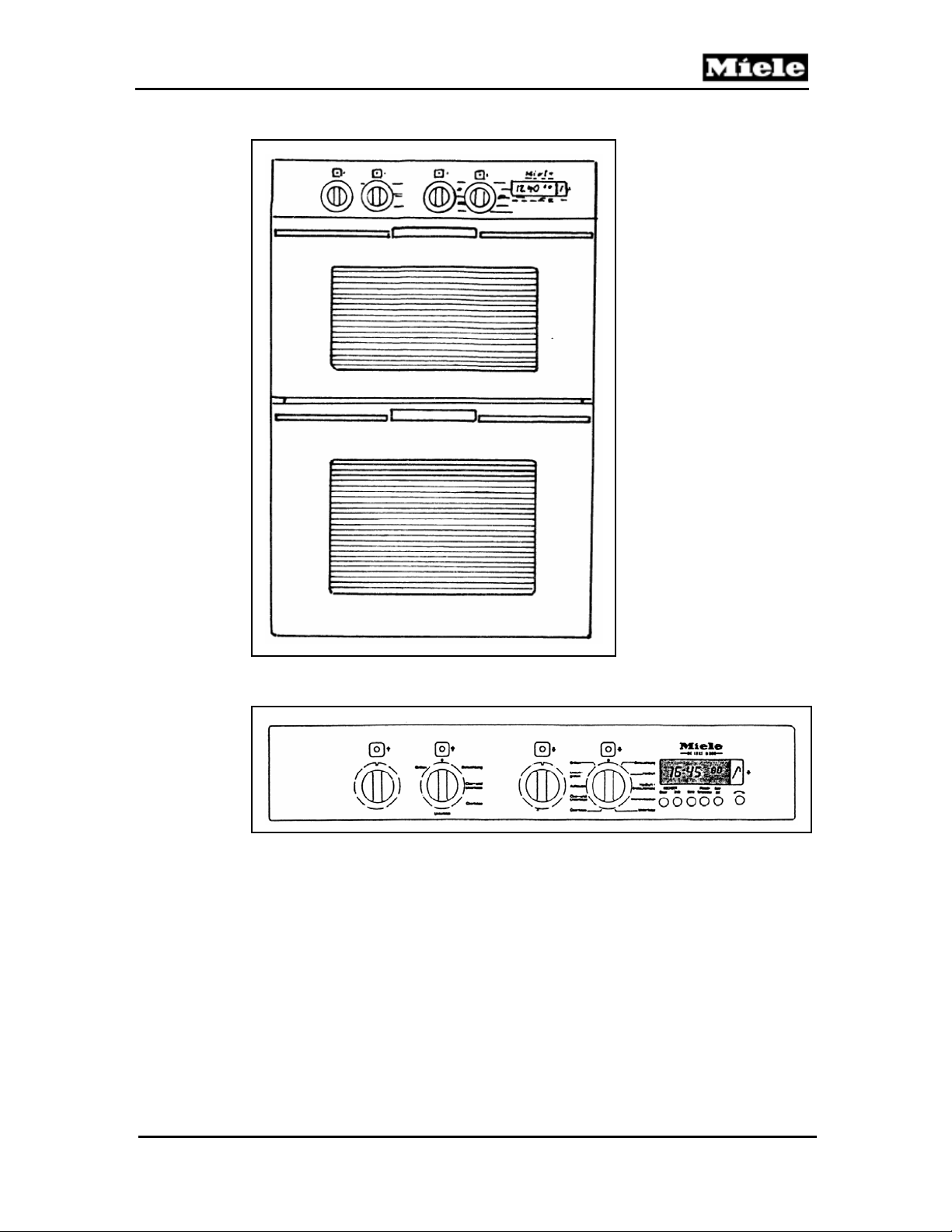
1.2 H 809 B2 ............................................................................................................. 12
1.2.1 Features ................................................................................................. 12
1.2.2 Dimensions............................................................................................. 12
1.2.3 Net Weight.............................................................................................. 12
1.2.4 Casing .................................................................................................... 12
1.2.5 Electrical Connection.............................................................................. 12
1.2.6 Oven Interior........................................................................................... 13
1.2.7 Oven Doors ............................................................................................ 13
1.2.8 Heating ................................................................................................... 13
1.2.9 Grill Motor (Bottom Cavity) ..................................................................... 14
1.2.10 Fan: Hot Air (Bottom Cavity)................................................................... 14
1.2.11 Fan: Cooling (Top and Bottom Cavities) ................................................ 14
1.2.12 Oven Lighting ......................................................................................... 14
1.2.13 Oven Regulator ...................................................................................... 14
1.2.14 Temperature Limiter ............................................................................... 14
1.2.15 Double Thermostat (Bottom Cavity) ....................................................... 15
1.2.16 Selector Switch....................................................................................... 15
1.2.17 Timer ...................................................................................................... 15
1.2.18 Roast Probe............................................................................................ 16
1.2.19 Switch Panel........................................................................................... 16
1.2.20 Transformer ............................................................................................ 16
2

Technical Information
H806 Series – Mechanical Oven
Table of Contents - H806 Series – Mechanical Oven (continued)
2.0 Installation.............................................................................................17
2.1 Installation in a Tall Unit ..................................................................................... 17
2.1.1 Removal of the Oven Doors ................................................................... 19
3.0 Commissioning and Operation.............................................................20
3.1 Controls ............................................................................................................... 20
3.1.1 Clock/Timer ............................................................................................ 20
3.1.2 Light-Code Rings.................................................................................... 21
3.1.3 Temperature Regulator .......................................................................... 21
3.1.4 Function Selector.................................................................................... 21
3.2 H806 B2 Conventional Oven (Bottom Cavity) H809 B2 Conventional Oven
(Top Cavity)......................................................................................................... 23
3.2.1 Function Selector.................................................................................... 23
4.0 Description of Function.........................................................................25
4.1 Clock Timer ......................................................................................................... 25
4.1.1 Electronic Timer Model 13140-002 (F 140) ............................................ 25
4.2 Cooling Air and Ventilation .................................................................................. 29
4.2.1 Combi Oven............................................................................................ 30
4.2.2 Conventional Oven ................................................................................. 30
5.0 Service and Maintenance ......................................................................31
5.1 Removal from a Housing Unit ............................................................................. 31
5.2 Electrical Components ........................................................................................ 33
5.2.1 H806 B2.................................................................................................. 33
5.2.2 H809 B2.................................................................................................. 35
5.3 Timer ................................................................................................................... 37
5.3.1 Removal ................................................................................................. 37
5.4 Fascia Panel........................................................................................................ 38
5.4.1 Removal ................................................................................................. 38
5.5 Light-Code Indicator Surrounds .......................................................................... 38
5.5.1 Removal ................................................................................................. 38
5.6 Oven Cavity Light ................................................................................................ 39
5.6.1 Removal (Top Cavity)............................................................................. 39
5.6.2 Removal (Bottom Cavity)........................................................................ 39
5.7 Thermostat .......................................................................................................... 40
5.7.1 Removal ................................................................................................. 40
5.8 Removal of Components..................................................................................... 40
5.9 Oven Cavity......................................................................................................... 41
5.9.1 Top Cavity .............................................................................................. 41
5.9.2 Bottom Cavity ......................................................................................... 41
3

Technical Information
H806 Series – Mechanical Oven
Table of Contents - H806 Series – Mechanical Oven (continued)
6.0 Fault Diagnosis ......................................................................................42
6.1 Oven Temperature Measurements ..................................................................... 42
6.1.1 Test Unit ................................................................................................. 42
6.1.2 Test Procedure ....................................................................................... 42
6.2 Condensation Below the Doors........................................................................... 44
6.2.1 H806 B2, H809 B2.................................................................................. 44
6.3 Buckling of Oven Cavity Floor ............................................................................. 45
6.3.1 H809 B2 – Bottom Oven......................................................................... 45
6.4 Earth Leakage ..................................................................................................... 46
6.4.1 H809 B2 – Bottom Cooling Fan.............................................................. 46
H806 Series – Mechanical Oven – List of Figures
Figure 1-1: H806 B2 Overview.......................................................................................... 6
Figure 1-2: H806 B2 Control Panel ...................................................................................6
Figure 1-3: H809 B2 Overview.......................................................................................... 7
Figure 1-4: H809 B2 Control Panel ...................................................................................7
Figure 2-1: H806 B2 Installation...................................................................................... 17
Figure 2-2: H809 B2 Installation...................................................................................... 17
Figure 2-3: Installation Overview..................................................................................... 18
Figure 2-4: Raising the Lever.......................................................................................... 19
Figure 2-5: Removing the Door....................................................................................... 19
Figure 3-1: Temperature Regulator................................................................................. 20
Figure 3-2: Function Selector Combi-Oven..................................................................... 20
Figure 3-3: Function Selector.......................................................................................... 23
Figure 4-1: Electronic Timer Model 13140-002 (F 140) .................................................. 25
Figure 4-2: Cooling Air and Ventilation ........................................................................... 29
Figure 5-1: Removal from a Housing Unit....................................................................... 31
Figure 5-2: Cover Plate ................................................................................................... 32
Figure 5-3: Electrical Components – H806 B2................................................................ 33
Figure 5-4: Electrical Components – H809 B2................................................................ 35
Figure 5-5: Removing the Pushbutton Knobs ................................................................. 37
Figure 5-6: Levering Off the Cap..................................................................................... 37
Figure 5-7: Removing the Timer Clock ........................................................................... 38
Figure 5-8: Oven Cavity Light Removal (Top Cavity)...................................................... 39
Figure 6-1: Test Procedure ............................................................................................. 42
4

Technical Information
H806 Series – Mechanical Oven
H806 Series – Mechanical Oven – List of Tables
Table 1-1: H806 B2 Dimensions ....................................................................................... 8
Table 1-2: H806 B2 Electrical Connection ........................................................................ 8
Table 1-3: H809 B2 Dimensions ..................................................................................... 12
Table 1-4: H809 B2 Electrical Connection ...................................................................... 12
Table 5-1: List of Components – H806 B2 ......................................................................34
Table 5-2: List of Components – H809 B2 ......................................................................36
Table 6-1: Test Procedure Settings ................................................................................ 43
Table 6-2: H806 B2 - Parts Required.............................................................................. 44
Table 6-3: H809 B2 - Parts Required.............................................................................. 45
Table 6-3: White Models Only (Applicable to both models) ............................................ 45
Table 6-4: H809 B2 Bottom Oven - Parts Required........................................................ 46
5

Technical Information
H806 Series – Mechanical Oven
1.0 Construction and Design
Figure 1-1: H806 B2 Overview
Figure 1-2: H806 B2 Control Panel
6

Technical Information
H806 Series – Mechanical Oven
Figure 1-3: H809 B2 Overview
Figure 1-4: H809 B2 Control Panel
7

Technical Information
H806 Series – Mechanical Oven
1.1 H806 B2
1.1.1 Features
Double oven for installation in a tall unit.
1.1.2 Dimensions
Height 1035 mm
Width 595 mm
Depth 544 mm
Recess 1025 – 1032 mm
560 – 568 mm
Size 550 mm
Table 1-1: H806 B2 Dimensions
1.1.3 Net Weight
Approx. 89.2 kg
1.1.4 Casing
Zinc-plated sheet steel
1.1.5 Electrical Connection
Voltage 2/N 380 V, 50 Hz
Connected Load 5.6 kW
Fuse Rating 16 A
Supply lead 4-core without plug
Table 1-2: H806 B2 Electrical Connection
8

Technical Information
H806 Series – Mechanical Oven
1.1.6 Oven Interior
1.1.6.1 Top Cavity
Enameled, Volume 48 l.5
Rear panel, side liners and roof are catalytically enameled and
replaceable.
Combi system with 9 functions.
Temperature-regulated infra-red grill.
Temperature controlled cooking with Roast Probe between 30°C and
99°C.
1.1.6.2 Bottom Cavity
Enameled, Volume 48 l.
Rear panel, side liners and roof are catalytically enameled and
replaceable.
Convention heating with roof and floor elements and 4 functions.
1.1.7 Oven Door
Removable
1.1.8 Heating
1.1.8.1 Roof and Floor Heating (Top and Bottom Cavity)
Visible roof heater element: 1250 W
Full rating achieved by switching in series with the infra-red heating
element.
Concealed floor heater element: 1300W
1.1.8.2 Fan Heating (Top Cavity)
Circular heater element: 2500 W
1.1.8.3 Grilling (Top and Bottom Cavity)
Hinged infra-red heater element: 2150 W
9

Technical Information
H806 Series – Mechanical Oven
1.1.9 Grill Motor
2 x 5 W built-in grill motors for double spit
1.1.10 Fan: Hot Air (Top Cavity)
Air circulated by single fan
Removable impeller (Left-hand thread)
1.1.11 Fan: Cooling (Top and Bottom Cavity)
Transverse-flow ventilator QLZ 06 at top
Transverse-flow ventilator QL 4 at bottom
Cool air drawn in through vent grille at bottom of appliance and
discharged through the handle strip.
1.1.12 Oven Lighting
E 14 bulb, 40 W, 220 V, 300°C
1.1.13 Oven Regulator
Selection of oven temperature for all the available functions between 0
and 275°C.
1.1.14 Temperature Limiter
A safety thermostat in each of the cavities limits the temperature for all
oven functions.
1.1.15 Double Thermostat (Top Cavity)
For fan assisted automatic roasting: 230°C.
For cooling fan.
1.1.16 Selector Switch
Selection of the following oven functions:
10

Technical Information
H806 Series – Mechanical Oven
1.1.16.1 Top Cavity
Light
Fan heating
Fan and automatic roasting
Intensive baking
Floor heating
Roof heating
Roof and floor heating
De-frosting
Hot air grilling
Grilling
1.1.16.2 Bottom Cavity
Light
Roof and floor heating
Roof heating
Floor heating
Grilling
1.1.17 Timer
Top cavity
Model 13140-002 (140)
Electronic clock
Cook/roast/bake: 1 min. – 5 h. 59 min.
Pre-selection: Max. 23h. 59 min.
Temperature-controlled roasting in oven: 30°C - 99°C
Minute timer: 1 min. – 5 h. 59 min.
1.1.18 Roast Probe
Temperature sensor (Meat probe)
1.1.19 Switch Panel
Glass with illuminated switch surrounds 6 x 12 V, 1 W bulbs
1.1.20 Transformer
12 V, 5.5 VA for light-code rings
11

Technical Information
H806 Series – Mechanical Oven
1.2 H 809 B2
1.2.1 Features
Double oven for installation in a tall unit
1.2.2 Dimensions
Height 886 mm
Width 595 mm
Depth 544 mm
Recess 876 – 880 mm
Size 560 – 568 mm
Table 1-3: H809 B2 Dimensions
1.2.3 Net Weight
Approx. 83.5 kg
1.2.4 Casing
Zinc-plated sheet steel
1.2.5 Electrical Connection
Voltage 2/N 380 V, 50 Hz
Connected load 5.2 kW
Fuse Rating 16 A
Supply lead 4-core without plug
Table 1-4: H809 B2 Electrical Connection
12

Technical Information
H806 Series – Mechanical Oven
1.2.6 Oven Interior
1.2.6.1 Bottom Cavity
Enameled, Volume 48 l.
Rear panel, side liners and roof are catalytically enameled and
replaceable.
Combi system with 9 functions.
Temperature-regulated infra-red grill.
Temperature-controlled cooking with Roast Probe between 30°C and
99°C.
1.2.6.2 Top Cavity
Enameled, Volume 30 l.
Rear panel, side liners and roof are catalytically enameled and
replaceable.
Conventional heating with roof and floor elements and 4 functions.
1.2.7 Oven Doors
Removable
1.2.8 Heating
1.2.8.1 Roof Heating (Top and Bottom Cavities)
Visible roof heating element: 1250 W
Full rating achieved by switching in series with the infra-red heating
element.
1.2.8.2 Floor Heating (Top Cavity)
Concealed heating element: 650 W
1.2.8.3 Floor Heating (Bottom Cavity)
Concealed heating element: 1300 W
13

Technical Information
H806 Series – Mechanical Oven
1.2.8.4 Fan Heating (Bottom Cavity)
Concealed heating element: 1300 W
1.2.8.5 Grilling (Top and Bottom Cavities)
Hinged infra-red heating element: 2150 W
1.2.9 Grill Motor (Bottom Cavity)
2 x 5W built-in grill motors for double spit
1.2.10 Fan: Hot Air (Bottom Cavity)
Air circulated by single 40 W fan
Removable impeller (Left-hand thread)
1.2.11 Fan: Cooling (Top and Bottom Cavities)
Transverse-flow ventilator QLZ 06 at top.
Transverse-flow ventilator QL 4 at bottom.
Cool air drawn in through vent grill at bottom of appliance and
discharged through the handle strip.
1.2.12 Oven Lighting
E 14 bulb, 40 W, 220 V, 300°C
1.2.13 Oven Regulator
Selection of oven temperature for all the available functions between 0
and 275°C.
1.2.14 Temperature Limiter
A safety thermostat in each of the cavities limits the temperature for all
oven functions.
14

Technical Information
H806 Series – Mechanical Oven
1.2.15 Double Thermostat (Bottom Cavity)
For fan-assisted automatic roasting: 230°C, for cooling fan.
1.2.16 Selector Switch
Selection of the following oven functions:
1.2.16.1 Bottom Cavity
Light
Fan heating
Fan and automatic roasting
Intensive baking
Floor heating
Roof heating
Roof and floor heating
De-frosting
Hot air grilling
Grilling
1.2.16.2 Top Cavity
Light
Roof and floor heating
Roof heating
Floor heating
Grilling
1.2.17 Timer
Bottom cavity
Model 13140-002 (140)
Electronic clock
Cook/Roast/Bake: 1 min. – 5 h. 59 min.
Pre-selection: Max. 23 h. 59 min.
Temperature-controlled roasting in oven: 30°C – 99°C.
Minute timer: 1 min. – 5 h. 59 min.
15

Technical Information
H806 Series – Mechanical Oven
1.2.18 Roast Probe
Temperature sensor (Meat probe)
1.2.19 Switch Panel
Glass with illuminated switch surrounds 6 x 12 V, 1 W bulbs
1.2.20 Transformer
12 V, 5.5 VA for light-code rings
16

Technical Information
H806 Series – Mechanical Oven
2.0 Installation
2.1 Installation in a Tall Unit
Figure 2-1: H806 B2 Installation
Figure 2-2: H809 B2 Installation
17

Technical Information
H806 Series – Mechanical Oven
Figure 2-3: Installation Overview
1. Connect the oven to the mains electrical supply.
2. Push the appliance into its recess so that the steam deflector strips
rest against the housing unit and align. It is important that the housing
unit has a recessed rear panel to provide a vent duct at least 100 mm
deep.
3. Use 4 screws; refer to Figure 2-3, to anchor the appliance in the
housing unit:
- 2 screws under the fascia panel;
- 2 screws behind the door of the lower cavity
To access the screws, remove the lower door as described in Section
2.1.1.
18

Technical Information
H806 Series – Mechanical Oven
2.1.1 Removal of the Oven Doors
Figure 2-4: Raising the Lever
1. Open the door.
2. Raise the lever; refer to Figure 2-4, on both sides of the door and
engage in the notch provided to lock the hinge.
3. Half close the door, grip at the side and lift off – refer to Figure 2-5.
4. To re-fit the door, position the locked hinges in the guide slots and
open the door fully.
5. Release the lever; refer to Figure 2-4, and press down so that it lies
flat.
Figure 2-5: Removing the Door
19

Technical Information
H806 Series – Mechanical Oven
3.0 Commissioning and Operation
3.1 Controls
H806 B2 Combi heating (top cavity)
H809 B2 Combi heating (bottom cavity)
Figure 3-1: Temperature Regulator
Figure 3-2: Function Selector Combi-Oven
The arrows on the fascia panel indicate which oven the regulators and
clock refer to:
Top
Bottom
3.1.1 Clock/Timer
The clock can be used to switch the Combi oven on and off automatically.
When an operation is pre-selected, the light-code ring on the temperature
regulator and the function selector are switched on. Once cooking begins,
the light above the temperature selector and the oven lighting is also
switched on.
20
This manual suits for next models
2
Table of contents
Other Miele Oven manuals

Miele
Miele DGC 7440 User manual

Miele
Miele H394B Parts list manual

Miele
Miele TX3587 User manual

Miele
Miele 09862980 User manual

Miele
Miele H6800BMCS User manual

Miele
Miele KM 360 G User manual

Miele
Miele H 4170 User manual

Miele
Miele M 6260 TC User manual

Miele
Miele H 4412 B User manual

Miele
Miele H4882BP User manual

Miele
Miele DG 6600 User manual

Miele
Miele DGC6500 User manual

Miele
Miele DGC 7860 User manual

Miele
Miele H6680BPBK User manual

Miele
Miele H4780B User manual

Miele
Miele MLT 4601 User manual

Miele
Miele H 4744 BP Parts list manual

Miele
Miele H2265E User manual

Miele
Miele H 6700 BM User manual

Miele
Miele DGC 7460 HC Pro User manual