MiFleet 3-Wire User manual

3-Wire & VPOD
Fleetsupport@mieet.us | www.mieet.us | 1.866.643.5338 opt. 2
What’s Included:
+
YELLOW is recomended installation
zones. Make sure the barcode of your
MiFleet hardware is facing the sky.
Fig. 4
car, and Ignition ON when the vehicle is powered ON. Good sources are
(Ignition Switch in fuse box, fuel pump).
4. Locate an installation location for placement of the MiFleet hardware.
Place the tracking device in line of sight’. Do not place under metal, or
adhere to the sub-frame chassis; this will cause interference. DEVICE
BARCODE MUST FACE THE SKY. For large commercial vehicles and trucks we
recommend xing the device to the dashboard or glovebox. For a smaller
compact vehicle we, recommend the same location as well as against the
dashboard on the back window.(Fig.3)
*To prevent the unit from moving or falling it is recommended to use a zip-tie to securely
fasten the device to the vehicle sub frame this is important so the Mi Fleet Device can accu-
rately gauge and report Acceleration based events.
5. To complete installation, all vehicles should validate the Ignition ON/OFF
functionality on the MiFleet software platform.
6. If the Platform does not report/show ignition changes please have the
installer verify the wire connections and/or proceed to call MiFleet support
for questions and troubleshooting steps.
Flashing
Network Device is trying to connectYes
Solid Device is receiving GPS signalsYes
Solid GPS signal acquiredYes
FlashingGPS
LED Type Behavior Normal? Status
Device is waiting GPS signal lockYes
O Device is not receiving powerNo
Fig. 5
* The SM & LG Fleet Device has two (2) status LEDs. Conrm the status using the
following blinking patterns:
Installation Guide
* For all vehicle types we recommend xing the device to the dashboard or glove box for
optimum proper usage. Device barcode must face the sky in order to be properly installed.
Avoid adhering to the sub-frame chassis as this will cause interference with the device. To
prevent the unit from moving or falling it is recommended to use a zip-tie to securely fasten
the device to the vehicle sub frame this is important so the MiFleet device can accurately
gauge and report acceleration based events.
Prior to Installation:
We recommend writing down the following information.
Name of Asset:
Asset Details (State, or Group):
ESN of Installed Device:
Current odometer:
Device Installation:
VBus Install:
1. Ensure the vehicle ignition is o and located free/clear of any obstructions.
2. Locate the vehicle’s OBD diagnostic port, this is usually located on the
driver’s side of the vehicle under the dash, hidden behind a cover plate or on
the side of a center console. (Fig.1)
*Some foreign/ luxury vehicles such as Toyota, Honda, BMW, etc. may have a slightly
dierent variation of the standard OBD plug and/or have the plug hidden in a nonstandard
location. If you have a foreign vehicle, and cannot locate your OBD port, please consult your
user manual or local dealership to help locate it.
3. Once you plug the MiFleet hardware into the OBD port turn the vehicle on
and let it run for 10 minutes. (Fig. 2)
Fig. 2Fig. 1
Fig. 3
4. Login to your MiFleet account. If all processed well, your device should
show up on your platform.
* If you do not see your device please call 1.866.MiFleet (643-5338) option 2 with your
account name and device ESN (located on label).
5. Locate an area to secure the MiFleet hardware. Place the tracking device in
line of sight where the barcode label can face the sky free of metal between
GPS tracker and sky. Securely mount device to the vehicle. (Fig. 3)
Continued on back
6. To complete installation, all vehicles should validate the Ignition ON/OFF
functionality on the MiFleet software platform.
7. If the Platform does not report ignition changes please move the vehicle in
a clear line of sight to the sky, unplug and plug back in device. Verify you get
a solid yellow and green light.
8. After verifying wiring is correct, proceed to call MiFleet support for ques-
tions and troubleshooting at 1.866.MiFleet (643-5338) option 2 with your
account name and device ESN (located on label).
3 - Wire Install:
For basic installation, install the included installation harness into the MiFleet
tracking hardware.
1. Power (Red Wire) The red wire must be connected to a constant power
source. Proper wiring will ensure you receive accurate reporting within the
MiFleet Tracking application.
*Incorrect wiring of the red wire can cause the unit to show incorrect power up events.
Good sources to tie Power into are (Battery, Alarm System, and Clock).
2. Ground (Black Wire) A good ground connection is vital for proper
performance. When wiring the black (Ground) wire from the harness, look for
a bolt, screw, or wire that contacts the bare metal of your vehicle’s chassis.
3. Ignition (White Wire) A switched power source is only ON when the
ignition is keyed ON - connect the White Wire from the Harness to a switched
power source, so that the performs the Ignition OFF when you turn OFF the
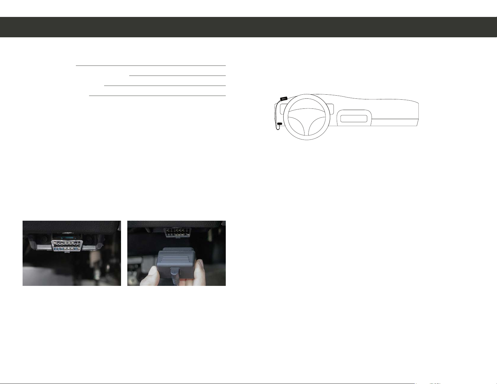
DO NOT MOUNT DIRECTLY UNDER STEARING WHEEL
This manual suits for next models
1
Popular Automobile Accessories manuals by other brands

Sensit
Sensit VMD Set up and operating instructions

Fiat
Fiat 2015 BLUE&ME Owner's manual supplement

Performance
Performance 5613 installation instructions

Dometic
Dometic Micro Heki Installation and operating manual

NavLinkz
NavLinkz RL4-LR16-8 manual

Metra Electronics
Metra Electronics 95-9313B installation instructions

Roxor
Roxor 1503AUA00031N Work instructions

dirna Bergstrom
dirna Bergstrom bycool green line COMPACT 1.4 Mounting instructions

FVC
FVC Sprinter Headliner Shelf installation guide

POLITECNICA 80
POLITECNICA 80 checkTEMP Time installation manual

Curtis
Curtis 1POLXP1000WS Installation & owner's manual

FH Group
FH Group FH1026 installation manual


