Sensit VMD Installation manual

SENSIT® VMD
SETUP &OPERATING INSTRUCTIONS
2
FOR YOUR SAFETY
NOTICE: This safety symbol is used to indicate a potentially hazardous situation which, if not avoided, may result
in minor or moderate injury.
WARNING: Disassembly and maintenance is forbidden in explosive atmosphere.
WARNING: Follow the manual instructions and testing methods.
WARNING: Any disassembly or repair of the instrument must be done by a factory certified technician.
WARNING: Clean lenses prior to each use with a lint free or microfiber cloth for best results.
WARNING: When not in use refer to transport position recommendation to prevent potential damage.
WARNING: While the VMD is weather resistant, it is recommended to remove the instrument and store it in the
vehicle when necessary to avoid prolonged exposure to extreme weather (i.e. heavy rain or snow).
DANGER: Use extreme caution when monitoring the tablet computer when driving. Rely on the audible alarm
instead of any visual indication while driving. Any adjustment should be made only when the vehicle is safely
stopped and away from traffic.

3
CONTENTS
For Your Safety....................................................................................................................................................................................2
Contents...............................................................................................................................................................................................3
Parts and Accessories..........................................................................................................................................................................4
Standard Parts (Included)................................................................................................................................................................. 4
Mounting Kit (VMD)..........................................................................................................................................................................4
Accessories......................................................................................................................................................................................4
Mounting Kit (Tablet)........................................................................................................................................................................4
Product and Technology Description....................................................................................................................................................5
Specification.........................................................................................................................................................................................6
Sensor Specifications.......................................................................................................................................................................6
Product Specifications......................................................................................................................................................................6
Explanation of ppm/m...........................................................................................................................................................................7
Installation............................................................................................................................................................................................ 8
Install VMD Instrument.....................................................................................................................................................................8
Install Tablet Computer ..................................................................................................................................................................10
Getac Tablet Connections.............................................................................................................................................................. 11
User Interface.....................................................................................................................................................................................12
Description of Interface Buttons .....................................................................................................................................................13
User Setup Tab .............................................................................................................................................................................. 15
Operation and Use............................................................................................................................................................................. 16
Calibration.......................................................................................................................................................................................... 17
Advanced Calibration ......................................................................................................................................................................... 18
Plotting Surveys ................................................................................................................................................................................. 19
Converting to .kml and Exporting ...................................................................................................................................................19
Pairing a PMD....................................................................................................................................................................................20
Importing Calibration Data Into SCAL ................................................................................................................................................21
Export Data from Tablet to Removable Media................................................................................................................................21
Import Data into SCAL....................................................................................................................................................................21
Troubleshooting..................................................................................................................................................................................22
Communication Issues and Re-Pairing Bluetooth Connection....................................................................................................... 22
Double Check the Following Items:............................................................................................................................................22
Power Cycle VMD and Tablet ....................................................................................................................................................22
Re-Pairing Bluetooth Connection ...............................................................................................................................................23
Notes..................................................................................................................................................................................................25
Warranty............................................................................................................................................................................................. 28

4
PARTS AND ACCESSORIES
STANDARD PARTS (INCLUDED)
360-00481 VMD Bluetooth antenna
360-00482 Tablet Bluetooth antenna
385-00159 Tablet Bluetooth antenna extension cable
(right angle)
330-00097 Tablet Bluetooth antenna clamp
360-00471 Tablet GPS antenna
385-00114 VMD power harness assembly
385-00160 Tablet vehicle power supply
360-00517 Tablet dock
882-00092-SN Calibration cell (with mounting arm and
thumbscrew)
882-00137 Extra power harness cover
360-00430 5A automotive fuse for power harness
MOUNTING KIT (VMD)
870-00428 Mounting kit (includes parts below)
330-00078 Hitch pins (2)
360-00426 Jam bolt
360-00427 L-bracket
360-00428 VMD bar bracket
360-00429 Hitch stabilizer
ACCESSORIES
870-00076 VMD shield
MOUNTING KIT (TABLET)
870-00074 Mounting kit (includes parts below)
360-00473 Base w/ 2” Ball & Clamps
360-00474 Arm
360-00475 Plate (VESA 75)
5
PRODUCT AND TECHNOLOGY DESCRIPTION
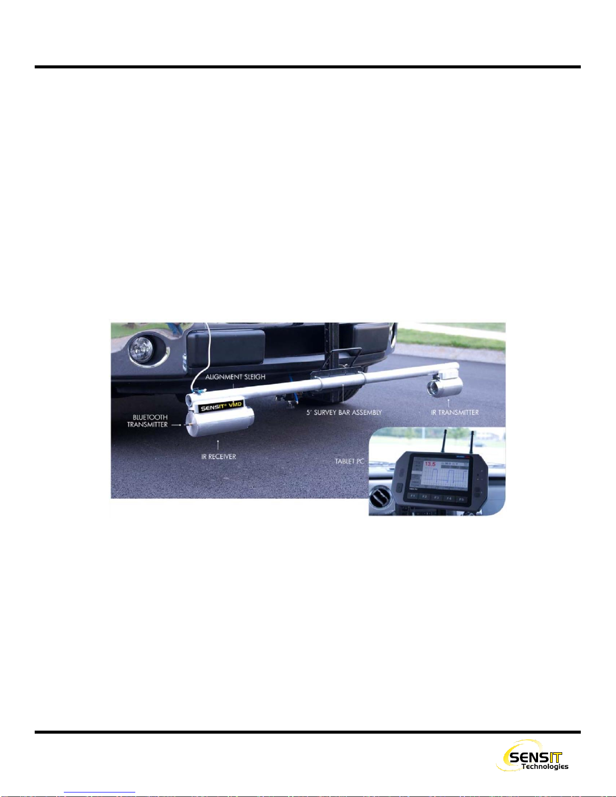
The SENSIT VMD is a vehicle-mounted natural gas leak survey instrument. It uses IR Absorption Spectroscopy technology
for extremely accurate and consistent readings that are entirely methane specific. The SENSIT VMD uses an open-path
system, which consists of 2 modules that are mounted on a bar. One half emits a light source, which travels through the
space between the modules into the other half which receives the signal. The amount of natural gas (methane) in the path
affects how much of the light source is absorbed, which is translated into a parts-per-million-per-meter (ppm/m) reading.
The entire assembly is mounted to the front of a vehicle on a large L-bracket, which is received by a 2” hitch. The SENSIT
VMD is powered by a single cable coming from the battery of the vehicle, and can be removed easily to allow for very fast
and simple removal and storage of the instrument. The data it gathers is sent via Bluetooth to a rugged tablet computer in
the cab of the vehicle. The user is shown readings in real time (at a rate of one reading every 200ms), on a very easy to
read graphical interface.
The SENSIT VMD, in addition to using Bluetooth communication, also utilizes a built-in GPS module in the tablet. Combined
with the software’s logging capabilities, the user can map a survey directly into Google Earth, to see a detailed map of the
survey with a breadcrumb trail of the path driven and readings found.

6
SPECIFICATION
SENSOR SPECIFICATIONS
Sensitivity: 0.1 ppm/meter methane at a max speed of 25mph
Measurement Range: 1.0 to 1000 ppm/meter
Display Range: Automatic
Accuracy: ±10%
Alarms: Audible with adjustable set point
PRODUCT SPECIFICATIONS
System Voltage: 10-16 VDC
System Power Requirements: 84 watts max @ 12 VDC
VMD Size: 4 ft. to 8 ft. path length (5 ft. Standard)
Tablet Weight: 1.94lbs (0.88kg)
Tablet Size: 8.93” x 5.94” x 0.94” (227 x 151 x 24mm)
VMD Weather Resistance: IP54
Tablet Weather Resistance: IP65
Operating Temperature Range: -20˚F to 122˚F
Operating Humidity Range: 5 to 100% relative humidity
Installation Time: < 2 hours (typical)
7
EXPLANATION OF PPM/M
The SENSIT VMD displays its readings in parts per million per meter. This is a representation of the average gas
concentration over 1 meter, or roughly 3.3 feet. Many types of IR and laser based technology in the industry uses this
standard. For implementations that are not fixed point, and have a variable path length, the unit used is ppmm (parts per
million meter). The difference being that the reading would be a factor of the total distance of the path length, which can
change as the size of the gas plume changes.
In the case of the VMD, the path length is fixed at slightly more than 1m, which is taken into account in the software, and we
therefore say the reading is “per meter”, meaning over the total length, since it never changes.
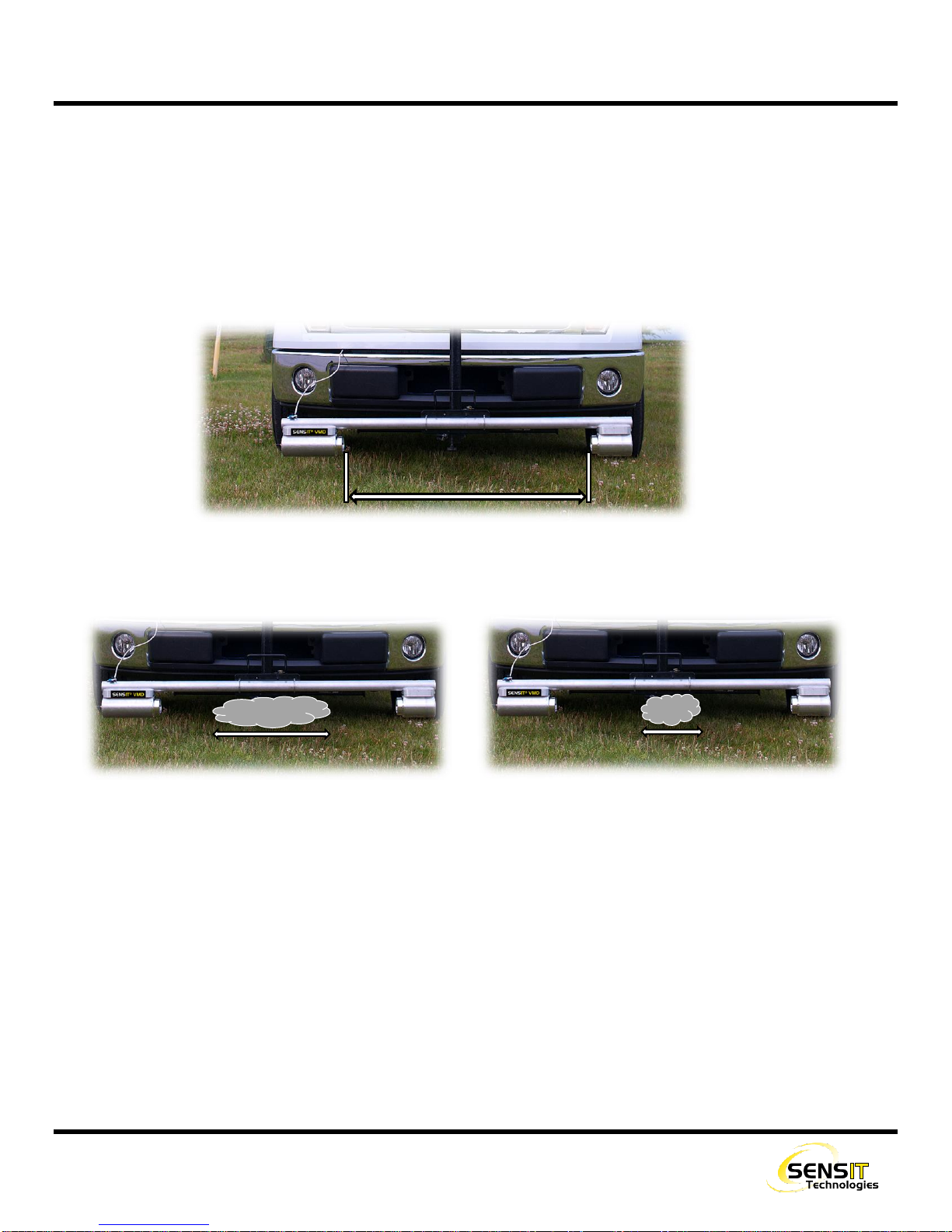
However, this reading is still essentially an average. For example, consider the following images:
On the left, there is a natural gas plume with a concentration of 40ppm, spanning 0.5m. On the right, there is a plume with
a concentration of 80ppm, spanning 0.25m. Both of these scenarios will yield the same reading of 20ppm/m. The plume
on the right is double the concentration, but half the distance, meaning the average concentration over the path length will
remain the same.
~1 meter
0.5 meter
40ppm
0.25 meter
80ppm

8
INSTALLATION
INSTALL VMD INSTRUMENT
1. Install a 2” front-mount hitch on the front of the vehicle. If a bolt on hitch cannot be sourced, a local welding shop should
be able to mount one for you as pictured below.
2. Insert the short end of the L-bracket into the hitch with the long side facing up. There are several adjustment holes for
distance in and out from the bumper. Insert the pin and install and tighten the hitch stabilizer. The hitch stabilizer
tightens the L-bracket to the hitch, and therefore the frame of the vehicle. This ensures that no extra vibrations are
transferred to the VMD.

9
INSTALLATION
3. Ensure that the jam bolt is backed out from the
bracket that is mounted to the VMD. Slide the
VMD and mounting bracket over the L-bracket,
lower the VMD to the desired position, and insert
the pin. Tighten the jam bolt. It is recommended
to use an anti-seize compound on the jam bolt.
4. Install the power harness assembly.
a. Route the power harness through the grill
and engine compartment to the battery. The
harness is 10ft long and should have some
slack left over.
b. The battery end of the power harness has two exposed wires, red for the positive terminal of the battery and black
for negative. Secure these wires to the battery. One method is to use crimp-on ring terminals that can then be
bolted to the battery terminals.
c. Plug in the power connector to the VMD.
d. It is recommended to use dielectric grease on
all connections to prevent corrosion.

10
INSTALLATION
INSTALL TABLET COMPUTER
There are various methods for mounting the tablet computer. There is not a universal mounting system that will fit all
vehicles, and therefore Sensit does not provide a full tablet mounting solution. What is provided is a ball-joint bracket and
mounting arm. The ball-joint and mounting arm can be attached to the back of the tablet with the provided hardware. The
arm can then be secured to a pole that is mounted in the cab of the vehicle (not provided). On an ATV or utility vehicle
application, there will usually be a roll bar or other similar structure that the arm can be attached to.
Alternatively, after market computer/tablet mounts are available from a variety of vendors. Most commonly, these will use
an arm or adjustable pole that will bolt to the front-passenger seat mounting points. This can either be the full solution
(which will mount to the tablet) or can sometimes be used in conjunction with the provided ball-joint and arm.
If you need assistance with this, contact SENSIT Technologies.
11
INSTALLATION
GETAC TABLET CONNECTIONS
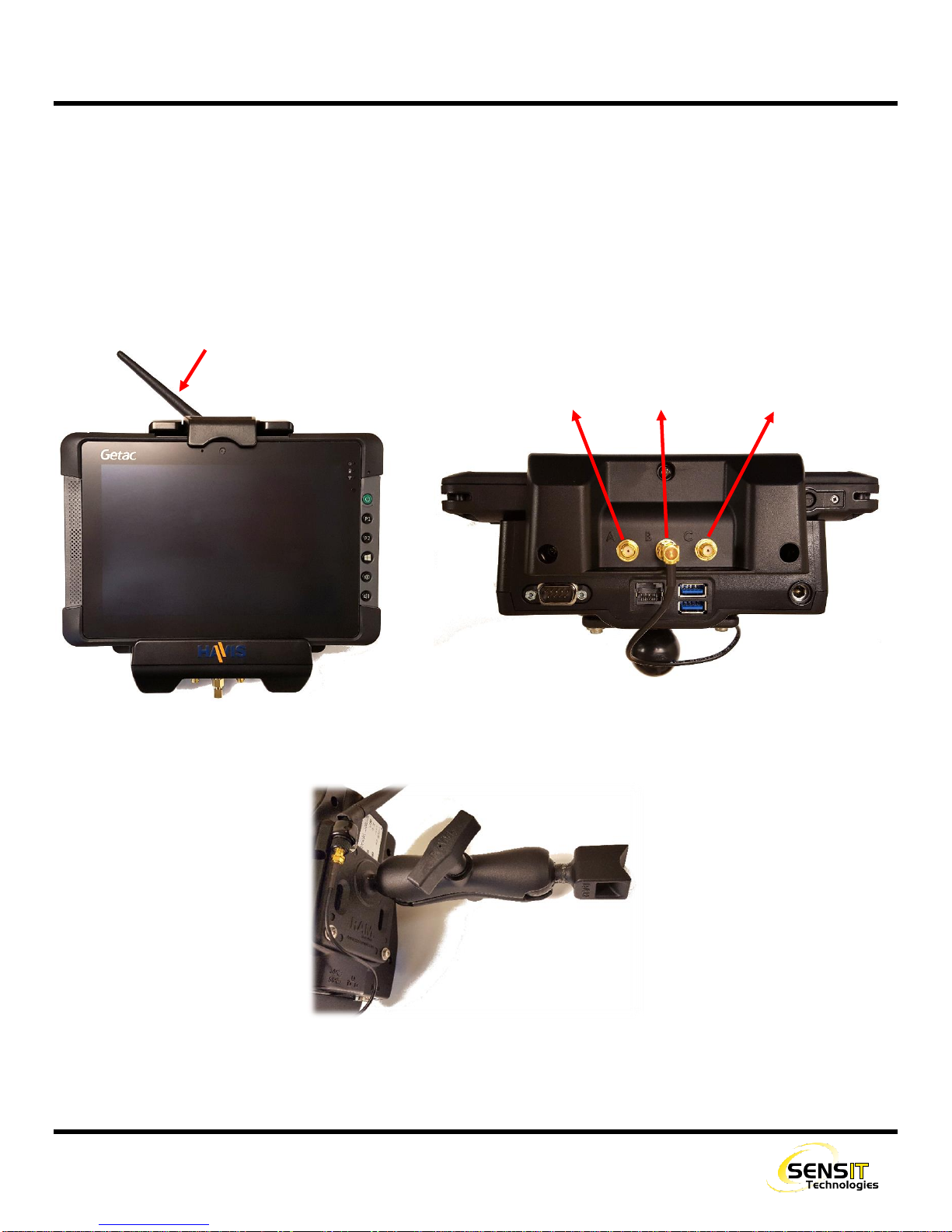
The provided tablet for the SENSIT VMD is the Getac T800. Also provided is a dock for the tablet, which has pass-through
connections for the Bluetooth and GPS signals. The antennas for each is attached to SMA connectors on the bottom of the
dock. The Bluetooth antenna (8”) will most likely be pre-installed. The GPS antenna has a magnetic puck with 10 feet of
cable and will need to be installed by the user.
Refer to the picture below for a description of each connection. Also shown is the provided mounting arm.
A: GPS B: BLUETOOTH C: WIFI (NOT USED)
BLUETOOTH ANTENNA
12
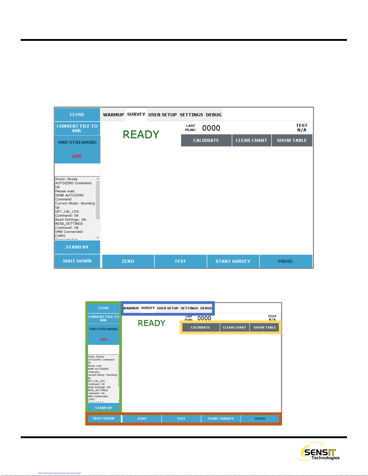
USER INTERFACE
The user interface of the SENSIT VMD is controlled by a tablet computer with a touch screen. The instrument streams all
data over Bluetooth to the tablet, where it is displayed in real time (200ms sample time).
The majority of the screen is reserved for survey data to be displayed. The bottom and left parts of the screen have
command buttons that can be used as needed. The top part of the screen has tabs for various display modes and menus.
Refer to the image below and descriptions on the next page for how each of these buttons are used.

13
USER INTERFACE
DESCRIPTION OF INTERFACE BUTTONS
Main Function buttons (bottom of screen):
1. POWER_ON_/_SHUT_DOWN
Shuts off the VMD. Does not close the application or
shut off the tablet.
2. ZERO
Sets a new zero baseline for the current survey (or
next survey). Does not alter the calibration or
sensitivity of the instrument.
3. TEST
Performs a self-test function of the instrument. A cell
with a known concentration of gas inside the
instrument is inserted into the detecting path. The
VMD detects this gas and shows the operator a
reading, as well as a test pass/fail indication.
4. START/STOP_SURVEY
Starts or stops a survey. No readings will be
displayed or recorded if a survey isn’t running. The
user will be prompted when starting a survey to either
save data to the previous log file or start a new one
(unless logging is disabled). Survey must be stopped
to calibrate the instrument.
5. PAUSE/RESUME
Pauses and resumes the survey instead of starting
and stopping. This will assume the user wants to
continue with the previous log file. Also used to
resume the survey if it gets interrupted due to low
light.
Function Buttons (left side of screen)
1. CLOSE
Closes the application but does not shut off the VMD.
This allows the user to bypass the warmup period if
the application is opened again. When used, a
timeout period of 10 minutes begins, after which the
VMD will be powered off. This is useful if the user
needs to access some other part of the operating
system, but wants to resume surveying afterwards.
2. CONVERT_FILE_TO_KML
Menu for converting a datalog file to ‘.kml’ file format
instead of ‘.csv’. ‘.kml’ files are used for viewing data
with a mapping/GIS application, such as Google
Earth. GPS data is required in order for a file to be
converted.
3. VMD/PMD_STREAMING
Status/indication icon for state of any streaming
options that are enabled.
4. GPS
Status/indication for GPS functionality. If no GPS
signal is available, the GPS text will be red and the
white box below it will be empty. If a GPS signal is
available, the GPS text will be green and the
coordinates will be displayed below.
5. STAND_BY
Puts the instrument in a low power state. User must
wait 120 seconds before use when it is woken up.

14
USER INTERFACE
Display modes / menu tabs (top of screen):
1. NORMAL/WARMUP
Initial startup and warmup screen. Only shown after
first power on and while the instrument is warming up.
Outputs basic sensor information. The user does not
need to interact with the instrument during this
process.
2. SURVEY
Main operation mode for use of the instrument. From
this mode the user can start and stop surveys, use
the self-test function, calibrate the instrument, etc.
For more information, see the sections on operation
and calibration.
3. USER_SETUP
Contains settings and configuration options that are
available to the user at any time. Alarm settings,
calibration logs, Bluetooth streaming, etc. For more
information, see the following section.
4. SETTINGS
Password protected settings menu that contains
factory level adjustments.
5. DEBUG
Password protected menu that outputs debug
information. Only used for troubleshooting purposes.
Other buttons (upper right of screen):
1. CALIBRATE
Starts the calibration process. The user will be
prompted to place the calibration cell on the
instrument. Calibration takes less than a minute. See
the calibration section for more information.
2. CLEAR_CHART
Clears the current information on the screen. This is
only visual and does not restart the survey or remove
any data from the log.
3. SHOW_TABLE/SHOW_GRAPH
Switches between displaying survey information with
a graph and with a table. The graph (default) has a
visual representation of the readings in the form of a
timeline, and is generally preferred.
15
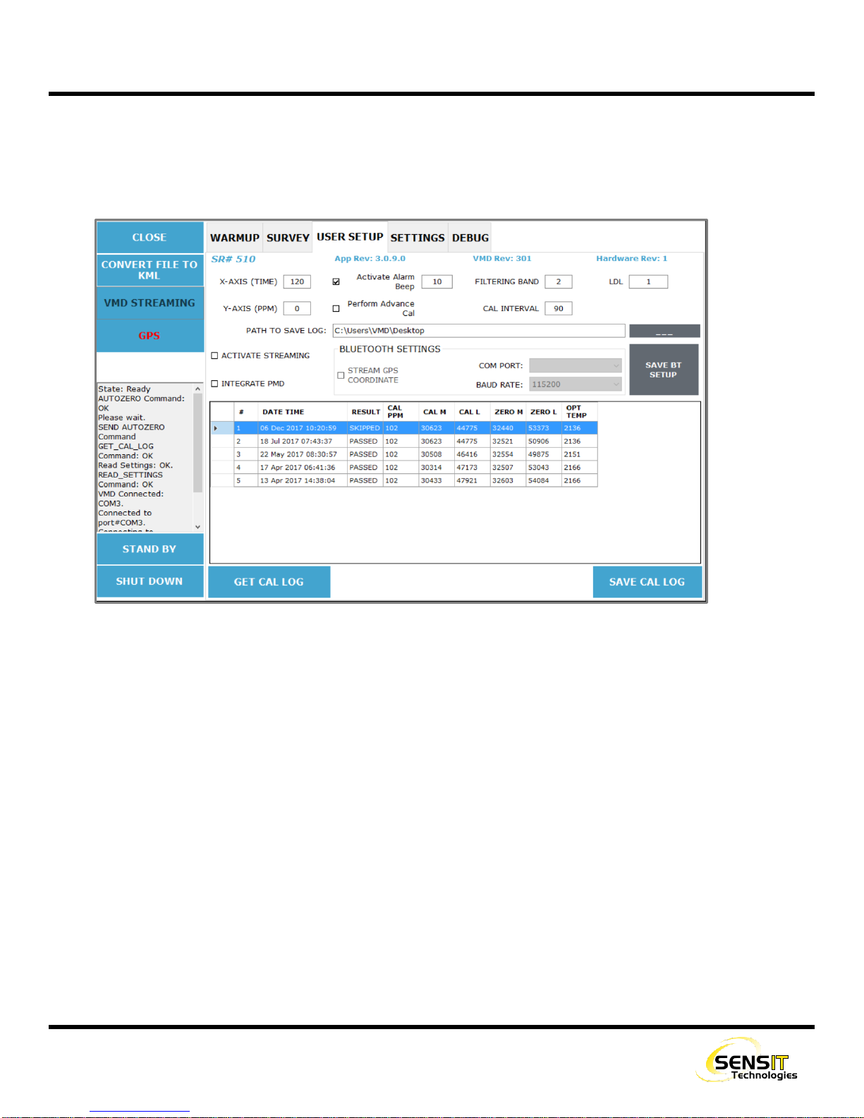
USER INTERFACE
USER SETUP TAB
The user setup tab contains settings and configuration options that are available to the user at anytime, as well as calibration
information. It is accessed by selecting the user setup tab from the top of the screen. The survey must be stopped in order
to access it.
From this menu, the user can:
Change the graph settings for time displayed on the X axis (default 120 seconds) and PPM range displayed on the Y
axis (default 0).
oFor the PPM setting, 0 means that there is no limit and the display will auto-range. Using another value will
fix the Y axis to that value and it will not adjust.
Change the alarm set point (default 10).
Change the Calibration Interval (default 90 days).
Setup Bluetooth streaming and/or PMD Bluetooth settings
View and export calibration data

16
OPERATION AND USE
WARNING: Always start any SENSIT VMD in a gas free environment to ensure a proper zero.
1. Activate the computer by pressing the button located on the lower right hand side of the housing. The system will boot
up.
a. If the VMD application does not automatically begin, double click the icon on the desktop screen.
2. Click power on to begin the warmup process, which will take approximately 8-12 minutes.
a. The graph and chart on the screen will show various diagnostic information during the warmup process, such as
the light level, sensor output, and internal temperature. This information is only pertinent for troubleshooting
purposes.
3. After the WARM UP and AUTOZERO complete, the display will show ready in the survey mode. READY should be
displayed in the upper left of the screen.
a. If the AUTOZERO failed, ZERO FAIL will be displayed. Please check that nothing is obstructing the light path and
that there is no dirt or other debris on the lenses. Try manually performing a zero by pressing the ZERO (F2)
BUTTON.
4. Travel to the area where the survey will begin.
5. If necessary, lower the VMD from the transport position (higher on the L-bracket) to the survey position (lower on the L-
bracket). The L-bracket allows for a broad range of height adjustment. Adjust as needed and tighten the jam bolt. In
general, the survey position should be as low as possible on the L-bracket without any potential of collision.
6. Use the TEST (F3) BUTTON to do a self-test of the instrument.
a. A test can be performed at any time during a survey as well. It will be logged along with your survey as test data
(appears differently than survey data).
b. A TEST PASS or TEST FAIL message will be displayed in the upper right of the display after the test has completed.
c. If the test fails, perform a calibration. A failed test pauses the survey. You can restart the survey by using the
RESTART (F5) BUTTON.
7. Press the start SURVEY (F4) BUTTON to begin the survey.
a. The user will be prompted to choose to add onto the previous log file or being a new log file. This is useful if one
survey or route has to be completed over multiple sessions.
b. Live readings will appear on the screen. By default this is shown as a graph, but can be displayed as a table if
desired.
c. If readings exceed the alarm point (10ppm/m default), an audible and visual alarm will be triggered.
d. If at any time the light path is obstructed, the survey will stop and low light will be displayed along with an audible
tone and warning message. Check for obstructions in the light path or any dirt or other debris on the lenses. Try
to manually zero the instrument by pressing the ZERO (F2) BUTTON.
8. Press the STOP (F4) or PAUSE (F5) buttons as necessary to stop or pause the survey.

17
CALIBRATION
WARNING: Calibration must be performed in a gas-free environment. Calibration cycles over 90 days are not
recommended. Using calibration kits other than recommended by SENSIT TECHNOLOGIES may cause inaccurate
readings. Repairs are required if the instrument fails to calibrate. Consult the factory for details.
The SENSIT VMD is calibrated with an external calibration cell assembly, which contains a known concentration of gas
trapped between two plates of glass. Unlike calibrating a conventional CGI, this calibration process does not use a
consumable. By default, the calibration cycle of the SENSIT VMD is 30 days, but can be increased or decreased to match
your company policies. There is no harm in performing a calibration process as often as desired (even daily).
1. Power on the instrument and wait for the warmup process to complete.
a. If the instrument is already powered on, calibration cannot be done while a survey is running. The survey must
be STOPPED and not PAUSED.
2. Hang the calibration cell on the bar of the VMD, so that the light will pass through it, up against the housing of either
module. Tighten the thumbscrew.
3. On the tablet, select the calibrate button. A dialog box will appear asking you to place the calibration cell on the bar.
Select OK. The calibration process will begin.
4. In the upper left of the screen, the current reading will be displayed as it is adjusted during calibration. This should be
very close to 100ppm/m. Once calibration is successful, READY will be displayed.
a. If calibration failed, CAL FAIL will be displayed. Attempt calibration again. If calibration continues to fail, contact
Sensit Technologies Service Department for assistance.
NOTE:In certain scenarios, if calibration fails, the instrument may need to have an advanced calibration
performed. In this case, the user will be prompted to do so with a dialog box after a failed calibration.
18
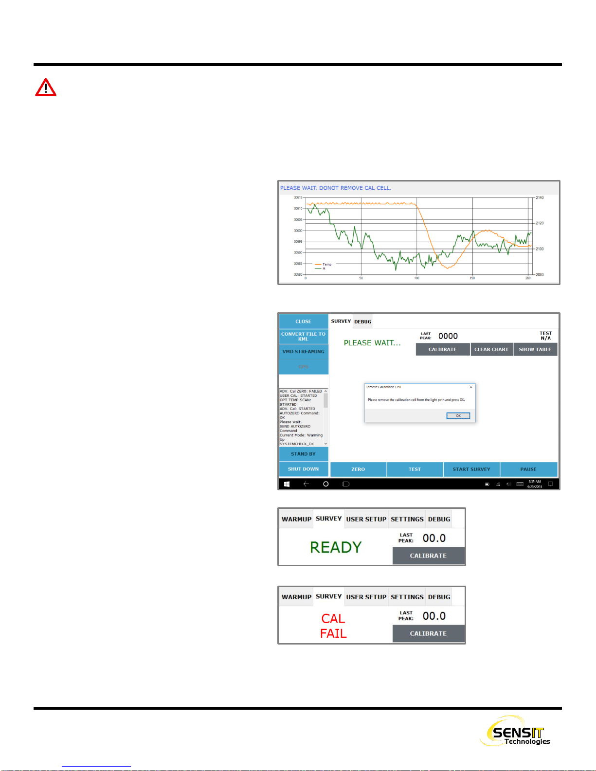
ADVANCED CALIBRATION
WARNING: Calibration must be performed in a gas-free environment. Calibration cycles over 90 days are not
recommended. Using calibration kits other than recommended by SENSIT TECHNOLOGIES may cause inaccurate
readings. Repairs are required if the instrument fails to calibrate. Consult the factory for details.
Beginning with software revision 3.10(app)/3.02(firmware), advanced calibration is automatically be performed instead of
the normal calibration on a 90 day cycle. This process is described below.
1. After the calibration has started, the display will
change to the Advanced Calibration screen. This
process will take between 2-5 minutes to
complete.
2. When the Advanced Calibration is done, the
display will return to the survey screen.
3. A “PLEASE WAIT…” message will be displayed.
The user will be asked to remove the calibration
cell so that a factory zero can be automatically
performed. Press “OK” after the cell has been
removed.
4. The “PLEASE WAIT…” message will continue to
display for a few seconds. Afterwards, the
calibration will be complete.
a. If calibration is successful, READY will be
displayed.
b. If calibration failed, CAL FAIL will be
displayed. Attempt calibration again. If
calibration continues to fail, contact Sensit
Technologies Service Department for
assistance.
19
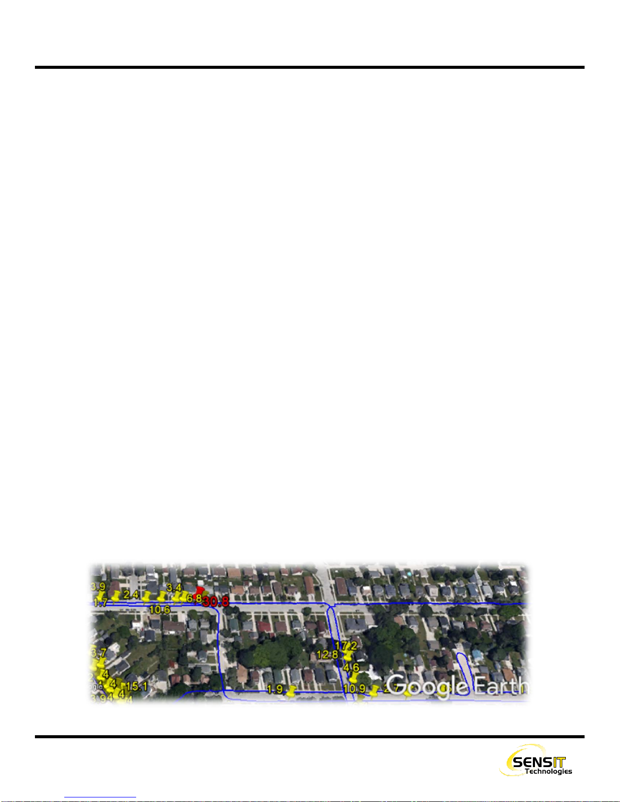
PLOTTING SURVEYS
The SENSIT VMD saves a data log file for every survey conducted. These files will contain the date, time, ppm/m reading,
and GPS coordinates if available. With valid GPS coordinates, these files can be converted to .kml format and viewed with
mapping software. This gives a breadcrumb trail for the route driven with the vehicle, including any readings found above
the chosen alarm points and any self-tests performed.
This section details how to convert these files, export them, and view them in Google Earth.
CONVERTING TO .KML AND EXPORTING
1. Power on the tablet computer. Allow it to fully boot and load the VMD application.
2. From the VMD application, select the CONVERT FILE TO KML from the upper left of the screen. The VMD does not have
to be powered on.
3. On the following screen, select SELECT FILE TO CONVERT. A file select window will appear.
4. Navigate to the location datalog file(s) that you want to convert. By default, the VMD will save log files to the desktop.
5. Select one or more files and hit OPEN. You will be returned to the previous screen.
6. Make any adjustments necessary to the pin assignments. Anything below the value chosen for the yellow pin will not
be shown on the map.
7. If you are planning to export right away to a flash drive, insert the drive now.
a. The USB port is on the right side of the tablet. Access it by pushing down the cover and lifting up.
8. Select CONVERT. A save window will appear.
a. If you get an error message, this means that one or more files you have chosen did not have valid GPS
coordinates. Any valid files in the selection can still be converted.
9. Navigate to the location that you would like to save the files to. If you are exporting to a flash drive, select the drive
from the list on the left.
10. Select save. A message will appear confirming that you have successfully created .kml file(s).
11. The .kml files can be opened directly into Google Earth to view the data.

20
PAIRING A PMD
The SENSIT VMD and PMD have the ability to be used as a paired system. In this case, the PMD will be used in conjunction
with a vacuum system, with cones on the front of the vehicle being drawn from with the aid of a powerful external pump.
Readings from the PMD can be streamed real time using Bluetooth to the VMD tablet, so that the user has information from
both instruments at the same time.
Additionally, this information can be logged, along with the GPS coordinates from both instruments, which can then be
mapped with Google Earth. This is especially advantageous for use cases where the vehicle will be stopped when a reading
is found, and the leak will be pinpointed using the PMD. That way, the path of the vehicle is shown as well as where the
walking survey was conducted to find the leak.
When ordered as a system, the SENSIT VMD and PMD will be shipped already paired from the factory. If for some reason
this needs to be done in the field, contact Sensit Technologies for assistance.
Other manuals for VMD
1
Table of contents
Popular Automobile Accessories manuals by other brands


ROKIOTOEX
ROKIOTOEX Coyote Crossbars installation guide

Carrier TRANSICOLD
Carrier TRANSICOLD Vector 8500 Operation & service manual

Bestop
Bestop HighRock 4x4 42950 installation instructions

Seat
Seat 5FJ.071.691 installation instructions

CAR-connect
CAR-connect VAS 671 001 operating manual

AMiO
AMiO BF Series user manual