MIG-O-MAT Lotstar 141 User manual
MIG·O·MAT Mikrofügetechnik GmbH • Werksstrasse 20 • DE-57299 Burbach • Fon +49 (0) 2736 4154 0 • Fax +49 (0) 2736 4154 99
info@mig-o-mat.com · www.mig-o-mat.com
Operating Instructions
MIG-O-MAT Lötstar 141
175
241
301
Hydrogen Soldering Units
English

Contents
2BA_Lötstar_EN_Vers.07.2016
© MIG·O·MAT GmbH
Contents
Contents........................................................................... 2
1 General....................................................................... 4
2 Important safety warnings .......................................... 4
3 Description of operational process ............................. 7
4 Product description..................................................... 8
4.1 Product features MIG-O-MAT Lötstar units .............. 8
4.2 Safety devices ......................................................... 9
4.3 CE conformity .......................................................... 9
4.4 Delivery volume ......................................................10
4.5 Description of unit components...............................11
4.6 Description of unit top part ......................................12
4.7 Description of unit back...........................................13
4.8 Description of operating panel ................................14
5 Preparatory measures for initial operation................ 15
5.1 Unpacking and placement of unit............................15
5.2 Mounting of the unit top part ...................................16
5.3 Filling of the reactor with electrolyte ........................18
5.4 Filling of the vaporizer glass with vaporizer liquid....20
5.5 Connecting the unit to the mains.............................22
5.6 Setting of operating language in the display............23
6 Initial operation ......................................................... 24
6.1 Switch on the unit ...................................................24
6.2 Switch on the operating mode.................................24
6.3 Electrolyte filling level check ...................................24
6.4 Leak check .............................................................25
6.5 Select the burner nozzle .........................................26
6.6 Adjustment of the gas pressure at the operating
panel 27
6.7 Regulation of the burner flame at the burner hand
piece 28
6.8 Operating stops ......................................................28
6.9 After operation ........................................................28
6.10 Extinction of the flame at the burner hand piece .....30
7 Technical details....................................................... 31
8 Maintenance and repair............................................ 32
8.1 Maintenance ...........................................................32

Contents
© MIG·O·MAT GmbH BA_Lötstar_EN_Vers. 07.2016 3
8.1.1 Check and refill demineralized water in the reactor
33
8.1.2 Refilling of vaporizer liquid ...................................35
8.1.3 Cleaning of the vaporizer glass............................36
8.1.4 Cleaning of the dryer glass ..................................37
8.1.5 Exchange of the filter cartridge in the dryer glass 37
8.2 Service indications (display)....................................38
8.3 Malfunctions and warnings......................................38
8.4 Trouble shooting .....................................................40
8.5 Repair.....................................................................42
8.6 Transportation of the unit ........................................42
8.7 Removal of electrolyte ............................................43
8.8 Removal of vaporizer liquid.....................................44
8.9 Spare Parts & accessoires......................................45
9 Putting out of operation and waste disposal............. 51
9.1 Waste disposal of Lötstar unit .................................51
9.2 Waste disposal of electrolyte ..................................51
9.3 Waste disposal of vaporizer liquid...........................51
10 Manufacturer’s contact address ............................... 52
4BA_Lötstar_EN_Vers.07.2016 © MIG·O·MAT GmbH
1 General
The present Operating Instructions are part of the delivered
equipment. They must be ready for use at any time and remain
with the unit in case of resale.
We reserve the right to carry out technical modifications on the
unit due to advanced development.
An operating manual cannot take account of every conceivable
use. Contact your dealer or the manufacturer for further
information or in the event of problems which are not covered or
not sufficiently covered in this operating manual
2 Important safety warnings
Carefully read and observe before putting into operation!
The present unit operates with acid, flammable and –
depending on the type of vaporizer liquid – toxic substances.
Therefore, a predetermined operating sequence and strict
observance of the safety and protection measures described
below are prerequisite.
The present operating instructions cannot take each and every
specific regulation into consideration which might apply in
various countries. The operator of the unit must ensure that all
relevant local regulations concerning the prevention of
accidents and the use of hazardous substances are known and
observed.
MIG-O-MAT Lötstar soldering and welding units are
intended for soldering, welding and melting of metals.
Operation is allowed by industrial and commercial
businesses only.
The unit must be operated by specialized, trained staff only.
The operating instructions must be strictly observed. The unit
must not be operated by unauthorized persons or by children.
For reasons of safety, the unit must be connected to a
shockproof socket only. The technical data indicated on the
nameplate must correspond with the available local connection
conditions, particularly with regard to mains voltage and current
consumption values.
For maintenance and service works, in case of liquid inside the
unit and malfunctions, and when you have finished working with
the unit pull the main plug. In case of a malfunctioning please
contact your supplier or the manufacturer.
The unit must be opened by authorized and specialized staff
only!
Instructions for the
operator
Intended use
Operating staff
Mains connection
Risks due to electric
current

Important safety warnings
© MIG·O·MAT GmbH BA_Lötstar_EN_Vers. 07.2016 5
Electrolyte solution can cause severe chemical burns!
Always wear alkaline-resistant gloves and goggles when you
work with electrolyte solution! Do not eat or drink while filling
electrolyte solution into the unit!
Wash your hands after filling the reactor!
Avoid contact with eyes and skin! In case of contact with the
eyes rinse the open eye(s) under running water for several
minutes and seek medical advice. In case of contact with the
skin wash immediately with soap and rinse thoroughly.
If you have overfilled the unit, do not remove any excess
electrolyte by sucking it through a hose by mouth. There is a
risk of severe chemical burns! If you have overfilled the unit by
mistake, use a suitable alkaline-resistant suction device which
is not operated by mouth.
Electrolyte containers which are not completely empty must be
kept tightly closed and stored out of reach of unauthorized
persons, in particular of children. Thoroughly rinse empty
electrolyte containers with water. Then the container can be
disposed of into the ordinary waste. We recommend to contact
the local authorities for information on the use and waste
disposal of electrolytes.
Risk of fire and explosion! The vaporizer liquid is a flammable
substance! Keep away from ignition sources while filling
vaporizer liquid into the unit!
Avoid inhaling the vapors! Do not eat, drink or smoke while
handling the vaporizer liquid! Wear goggles and gloves!
MIG-O-MAT vaporizer liquid BLQ 1800 is not toxic. When using
other, methanol-containing vaporizer liquids, take into
consideration that these substances may be highly toxic! Read
and observe the relevant instructions on the labels of the
products used.
Risk of fire and explosion! Do not leave the unit switched on
unsupervised. The gas escaping from the unit is highly
flammable and explosive. The switched-on unit must be
operated with opened valve only until the flame ignites. Any
escaping gas which does not burn in a flame causes a high risk
of fire and explosion! For refilling the reactor keep away from
ignition sources! Even the open pressure-less reactor contains
highly explosive burnable gases.
To prevent the creation of electrostatic sparks immediately
before opening the reactor (e.g. for checking the filling level or
for refilling demineralized water), touch the cap nuts on the top
part of the unit or the metal screws on the housing with both
hands.
Risks caused by
electrolyte
Risks caused by
vaporizer liquid
Risks caused by
burnable gas and gas
flame

6BA_Lötstar_EN_Vers.07.2016 © MIG·O·MAT GmbH
Risk of burns and fire! Hang the torch hand piece with burning
flame onto the soldering stand for short operating stops. Ensure
that there is a sufficient distance between the flame and any
flammable items. Ensure that there is sufficient ventilation for all
soldering and welding operations!
The manufacturer cannot be held liable for damages on
persons, equipment or work pieces caused by improper use.
The operator is responsible for the correct instruction of the
operating staff.
Exclusion of liability

Description of operational process
© MIG·O·MAT GmbH BA_Lötstar_EN_Vers. 07.2016 7
3 Description of operational process
Lötstar units produce a hydrogen flame with very high
temperatures of up to approx. 2850°C.
In the integrated reactor, detonating gas is produced through
electrolysis from demineralized water.
The detonating gas is guided from the reactor to a condensate
separator to dry. Then, the gas is enriched with solvent vapours
in a vaporizer tank. The processed detonating gas is then
conducted through the gas hose to the burner hand piece via a
backfire protection device.
If the detonating gas ignites, it reacts releasing heat. The
remainder of the reaction is water (H2O).
Temperature and energy of the burner flame can be adjusted to
the soldering or welding job by the selection of a suitable nozzle
size and the type of vaporizer liquid.
The fine adjustment of the quantity of delivered gas is carried
out by the regulating wheel on the burner hand piece. The
operating pressure can also be set at the operating panel
depending on the required energy of the flame.
As soon as the valve at the burner hand piece is closed the gas
production is automatically interrupted.
Depending on the temperature of the electrolyte reactor the
ventilation device keeps on operating for a certain period of
time until the reactor has cooled down to 45°C. The ventilation
device is fitted with 3 speed ranges which are controlled
electronically.
The extremely low energy consumption and the low cost of
consumption goods (demineralized water, vaporizer liquid)
ensure extraordinarily low operating costs compared to other
procedures.
Operational principle
Adjustment of the
Lötstar
Stand
-
by mode
Economic efficiency

8BA_Lötstar_EN_Vers.07.2016 © MIG·O·MAT GmbH
4 Product description
4.1 Product features MIG-O-MAT Lötstar units
The MIG-O-MAT Lötstar units comprise the latest soldering
and welding technology.
The special top part makes operation, maintenance and
functional checks particularly easy. There is almost no
condensation inside the unit due to the special gas guiding
device. This increases both reliability and service life of the
units.
The MIG-O-MAT Lötstar units are equipped with a quick
analogous pressure control to allow operation of the units on
changing jobs or on more than one workplace. The operating
pressure is variable and is automatically kept precisely at a
constant value even when the ambient conditions change.
Additional advantages:
•Very high safety standard in compliance with DIN 32508
•Hydrogen-oxygen mixture burns without residues
•Easy operation
•Integrated leak detector check
•Microprocessor-controlled regulation of the operating
pressure
•Almost noiseless operation with temperature-controlled
ventilation device („whisper cooling“)
•Single or multi-workplace operation possible
•Low operating costs:
Any losses of liquid due to operational processes are
compensated by refilling demineralized water.
Exchange of the electrolyte is not required before approx.
1000-1500 operating hours.
No mineral wool padding necessary for drying the gas.

Product description
© MIG·O·MAT GmbH BA_Lötstar_EN_Vers. 07.2016 9
4.2 Safety devices
Lötstar units are designed and manufactured in compliance with
the latest technology standards. Operation is safe provided that
the safety and operating instructions are observed and provided
that the units are used only for applications for which they are
intended.
Safe operation of the units is ensured by means of the following
safety devices.
•Gas pressure monitoring by means of safety pressure
switch
•Temperature monitoring of the reactor and of the
transformer
•Flame barrier (backfire protection device) integrated in
burner hand piece
•Flame barrier (backfire protection device) and temperature
activated cut off valve at the gas outlet
•Main filters (EMC)
•Mains fuse
A high operating safety is guaranteed because gas is produced
only when it is required (i.e. when the valve at the burner hand
piece is open).
4.3 CE conformity
The present MIG-O-MAT Lötstar hydrogen soldering unit is in
compliance with all relevant CE marking criteria.
The declaration of conformity can be obtained from the
manufacturer.

10 BA_Lötstar_EN_Vers.07.2016 © MIG·O·MAT GmbH
4.4 Delivery volume
The delivery volume of the Lötstar units comprises:
•Lötstar soldering and welding unit
•Electrolyte, ready for use
•vaporizer liquid BLQ1800
•5 pieces of burner nozzles depending on type of unit
•gas hose 3.0 m long
•burner hand piece
•Torch stand with holder for nozzles
•filling funnel
•glass floating body for checking the electrolyte filling level
•1 pair of disposable rubber gloves
•goggles
•Operating Instructions
The units are supplied in special packing (reusable, please
store for possible future transportation, e.g. for service or repair
return shipment)
Product description
© MIG·O·MAT GmbH BA_Lötstar_EN_Vers. 07.2016 11
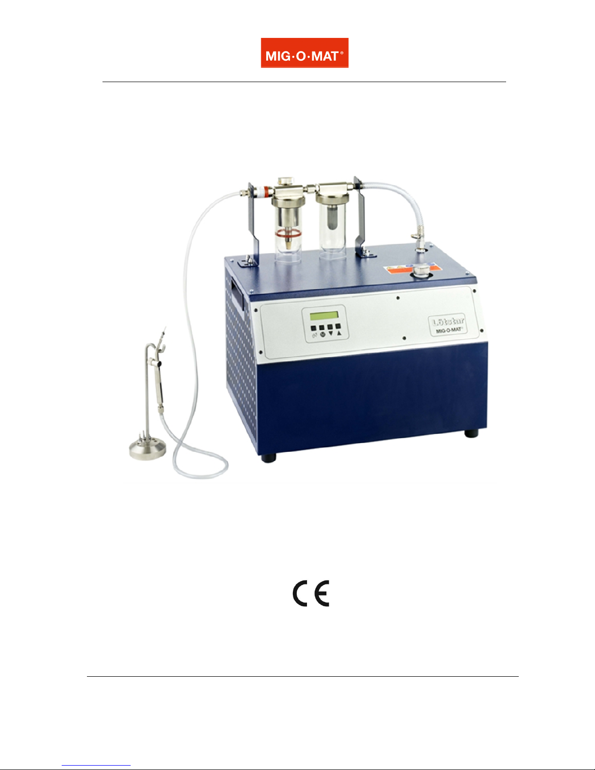
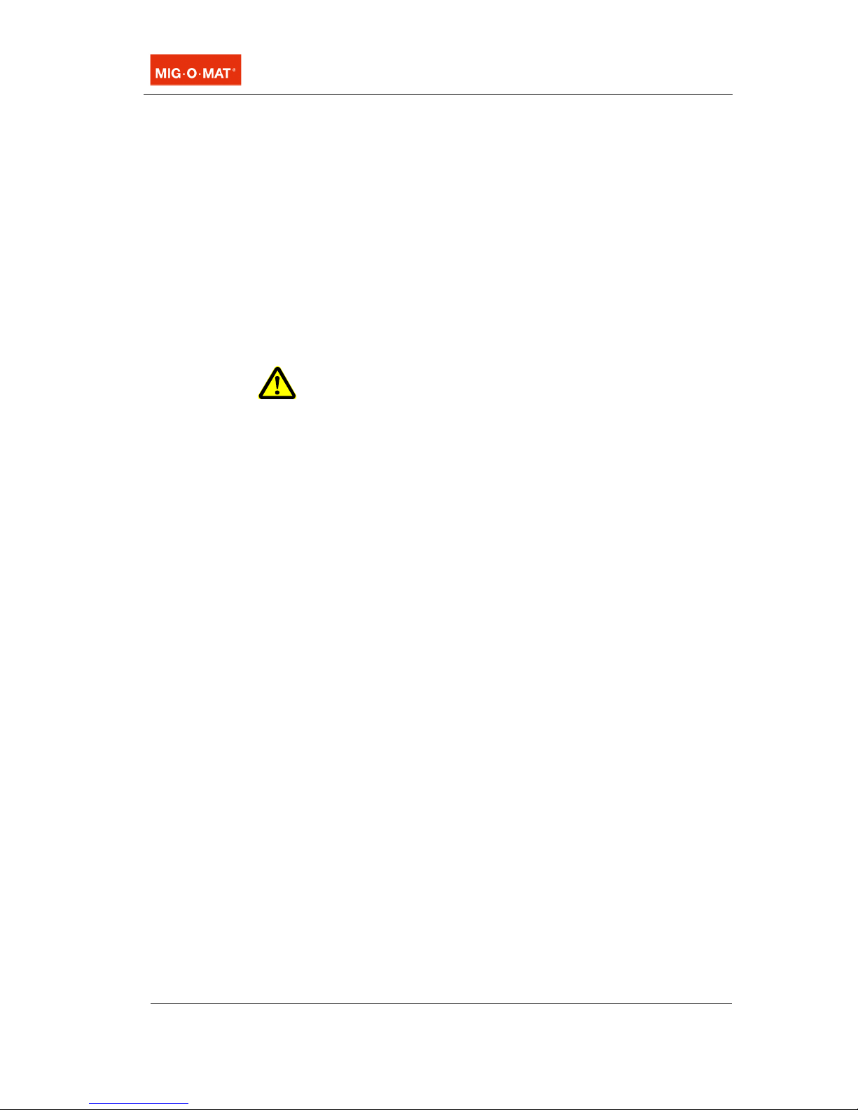
4.5 Description of unit components
Illustration 4.5. Unit front and side view (here Lötstar 300)
Unit top part with glasses for vaporizer liquid and condensate
separator. Moveable for an easy removal of the glasses.
Handles (on both sides)
Operating panel with display and operating keys
Ventilation openings (on both sides)
Burner hand piece
Holder for burner hand piece
A
B
C
D
E
F
A
C
D
E
F
B
12 BA_Lötstar_EN_Vers.07.2016 © MIG·O·MAT GmbH
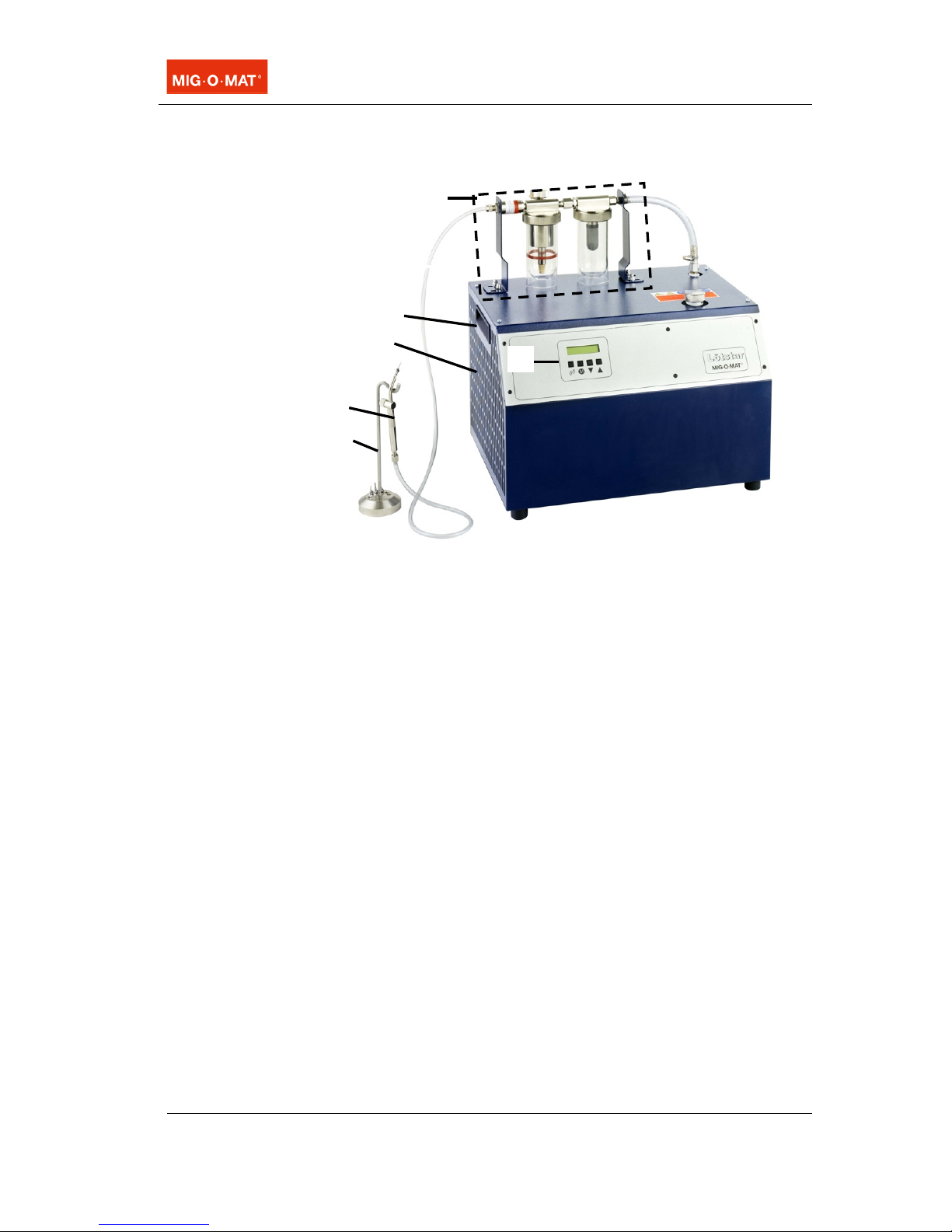
4.6 Description of unit top part
Illustration 4.6. Unit top part of Lötstar
Gas hose (PVC) to burner hand piece with connection to gas
outlet on the unit top part.
Check valve as protection against the flame backfiring into the
unit (flame barrier and temperature-sensitive gas cut-off).
Screw cap on filling duct for vaporizer liquid.
Screw connection for the gas hose at the reactor outlet.
Screw cap of filling duct
for electrolyte (for initial filling) or
for demineralized water (for refilling in case of low reactor filling
level).
Glass container for condensate separator (also termed dryer
glass) with filter piece.
Glass container for vaporizer liquid (also termed vaporizer
glass) with gas distributor (sintered cone).
A
B
C
D
E
F
G
A
B
C
E
D
F
G
Product description
© MIG·O·MAT GmbH BA_Lötstar_EN_Vers. 07.2016 13
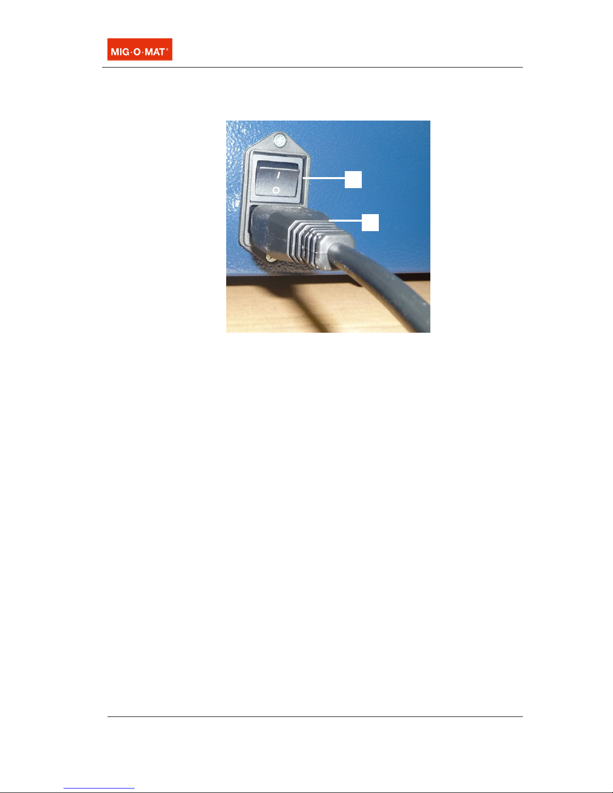
4.7 Description of unit back
Illustration 4.7. Mains socket with mains switch
Mains switch as main switch for switching off the unit during
longer operating stops, e.g. overnight, over the weekend, etc.
Plug-in mains cable connected with the mains socket.
A
B
A
B

14 BA_Lötstar_EN_Vers.07.2016 © MIG·O·MAT GmbH
4.8 Description of operating panel
Illustration 4.8. Operating panel with display and operating keys
Display
Top line – section on the left: indicates the actual value (mbar)
inside the unit.
Top line – section on the right: indicates the actual reactor
power which is required to produce the set gas pressure.
Indication range between 10% and 100% depending on the
actual state of the unit.
Bottom line: indicates the set pressure value (mbar) inside the
unit.
The display also shows service indications, operating hours,
display language, etc.
Key on/off for switching the gas reactor on and off.
Menu selector key to call the following settings and display
indications:
Operating language: The operating language can be selected,
available languages are German, English or French.
Operating hour meter: The operating hour meter shows the
hours during which the unit has produced gas.
Display service mode: The service mode of the display shows
the actual service status of the unit. The optimum on new or
newly serviced units is 100%. At 0% the Lötstar must be
serviced by an authorized service company.
Selector keys for changing and indicating the unit settings.
A
B
C
D / E
B
C
D
E
A
Preparatory measures for initial operation
© MIG·O·MAT GmbH BA_Lötstar_EN_Vers. 07.2016 15
5 Preparatory measures for initial operation
5.1 Unpacking and placement of unit
The unit is shipped in a suitable packing. Check the MIG-O-
MAT Lötstar unit for possible transport damages before initial
operation. In case of visible damages do not operate the unit
and contact your supplier and the forwarding agent
immediately.
If possible, keep the original transport packing in store for
possible later shipment for maintenance or repair purposes.
Or dispose of the packing material according to the relevant
local regulations on waste disposal. You can also return the
packing material to the manufacturer for disposal (shipment
charges to be paid by the customer).
The unit must be operated under permanent supervision only.
The workplace must allow free access to the unit. The operator
must be able to supervise the unit at all times. Possible warning
signals of the unit must be audible/visible.
For operation, place the unit on a dry and solid surface. Ensure
that the workplace is sufficiently ventilated! The cooling air must
circulate through the cooling openings on both sides of the unit.
Risk of electrocution due to humidity inside the unit!
Protect the unit from entering humidity!
Keep workplace and housing dry in order to prevent electrical
accidents and damages from the unit.
•Allowed ambient temperature during operation:
+5°C up to +40°C
•Allowed relative humidity of air during operation: max. 80 %
•Indoor operation only (no operation in the open)
•Protect the unit from direct or indirect heat sources (e.g.
heating elements, direct sunlight) to avoid overheating.
Check for transport
damages
Packing
Choice of w
orkplace
Placement
WARNING
Ambient conditions

16 BA_Lötstar_EN_Vers.07.2016 © MIG·O·MAT GmbH
5.2 Mounting of the unit top part
The preassembled unit top part is packed separately and must
be mounted onto the Lötstar base unit. The protecting foil
remain around the glass containers (serves as fracture
protection).
Risk of injury splintering glass!
Combustion of gas inside the glasses due to gross disregard of
the safety instructions can cause the glasses to burst.
Do not operate the unit without protective the hood (illustration
5.2.E.) over the glasses.
After replacing either one or both of the glasses, pull the
protective hood(s) over the new glass(es).
•1 fork wrench size 10 mm (or comparable, suitable tool).
•1 fork wrench size 19 mm (or comparable, suitable tool).
Illustration 5.2. Correctly mounted and connected unit top part
1. Use the 4 cap nuts (A) to screw the unit top part to the 4
threaded bolts on the Lötstar unit top (fork wrench 10 mm).
2. Remove the yellow screw cap (transport safety device) on
the reactor outlet (B). Please keep the yellow screw cap for
possible future service purposes.
3. Connect the gas hose to the reactor outlet by means of the
union nut (fork wrench 19 mm). Caution! Do not jam the
connection nut.
Then tighten the connecting nut by means of the fork
wrench. For this, hold the reactor at the filling duct with one
hand. A slight movement of the reactor is possible and
harmless because the reactor connection is elastic. Tighten
WARNING
Required tools
How to proceed
A
A
B
C
D
E
Preparatory measures for initial operation
© MIG·O·MAT GmbH BA_Lötstar_EN_Vers. 07.2016 17
the screw connection fast to avoid leaks in the pressure
system.
4. Connect the gas hose of the burner hand piece to the outlet
on the top part (C).
The unit top part is movable to facilitate the removal of the glass
containers.
18 BA_Lötstar_EN_Vers.07.2016 © MIG·O·MAT GmbH
5.3 Filling of the reactor with electrolyte
For the production of gas a certain amount of electrolyte
solution is required. When delivered, the unit is not filled with
electrolyte for reasons of safety.
The electrolyte is included in the delivery volume
Electrolyte is a strong caustic solution!
Risk of severe chemical burns on skin, mucous membranes
and eyes!
Risk of chemical burns of the mucous membrane caused by
inhaling of vapours!
Always wear protective gloves and goggles when handling
electrolytes to prevent chemical burns! Do not inhale the
vapours!
Store open containers with electrolyte at a safe place and keep
them out of reach of unauthorized persons, in particular of
children.
Please note! In order to avoid damages on the unit, use suitable
electrolyte and demineralized water only!
If in doubt contact the manufacturer or your supplier for
information.
Lötstar 141 Lötstar 175/241/301
1.8 litre electrolyte
solution
4.0 litre electrolyte
solution
1. Unscrew the closing cap from the filling duct (see illustration
5.2.D.) at the electrolyte reactor.
2. Place the clean funnel (included in the delivery volume) onto
the filling duct.
3. Carefully pour approx. 4/5 of the electrolyte (total quantity
see table in this section) into the filling duct of the reactor.
4. Carefully insert the glass float into the filling duct of the
reactor, with the thin end up. The tip of the float must be
flush with the edge of the duct.
5. If necessary refill liquid. The glass floating body must not
stand out from the edge of the duct by more than 5 mm.
Caution! In case of an overfilling there is a risk of damage
to the unit. If the reactor has been overfilled the excess
electrolyte must be removed from the reactor (for this
carefully read and observe the relevant safety and
procedure instructions in section 8.7.!).
CAUTION!
NOTE
Filling quantities
Electrolyte solution
How to fill electrolyte
solution
Preparatory measures for initial operation
© MIG·O·MAT GmbH BA_Lötstar_EN_Vers. 07.2016 19
The glass float remains in the filling duct for future filling
level checks.
6. Screw the closing cap back onto the filling duct and tighten
it.
7. The filling process is now finished.
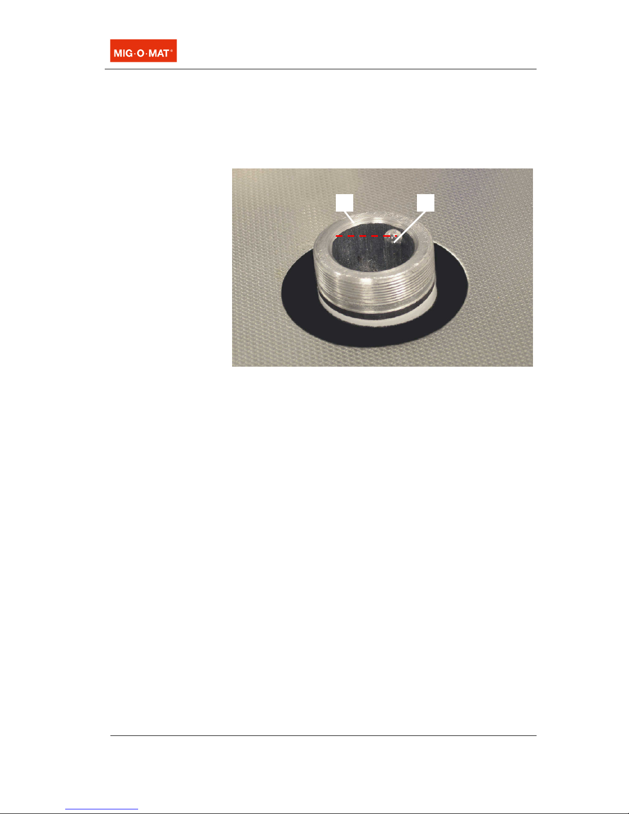
Illustration 5.3. Filling duct with glass float at maximum filling level
A
B

20 BA_Lötstar_EN_Vers.07.2016 © MIG·O·MAT GmbH
5.4 Filling of the vaporizer glass with vaporizer liquid
The use of vaporizer liquid is necessary for the soldering of
metals (except platinum). The flowing gas is enriched and
thereby produces a flame which is adjusted to the individual
properties of the metal.
We recommend the use of MIG-O-MAT vaporizer liquid BLQ
1800 (MIG-O-MAT Order No. 50.2501631, 1 litre). Unlike
other methanol-containing liquids MIG-O-MAT BLQ 1800 is
not toxic. Another advantage is that the burner hand piece
cannot be blocked by residues which may be contained in
other media (borax). In these cases the hand piece must be
replaced.
Vaporizer liquids are flammable! Therefore, please observe the
following safety instructions before filling.
Risk of fire and explosion due to ignition sources and
electrostatic charging!
Risk of ignition of the flammable liquids used for filling due to
ignition sources around the workplace!
Keep away from ignition sources when the vaporizer glass is
open or when you handle vaporizer liquid!
Risk of ignition of the flammable vaporizer liquids used for filling
due to electrostatic discharging!
Touch the cap nuts on the holding angle pieces of the top part
with both hands for a short period of time before you handle the
vaporizer liquid. This will branch off any possible electrostatic
charge of the operator without any risk!
Ensure that the workplace is sufficiently ventilated!
Risk of poisoning by toxic solvents when methanol-containing
vaporizer liquids are used!
Do not inhale the vapours!
Avoid contact with eyes and skin!
Wear protective gloves and goggles when handling hazardous
substances! Do not eat, drink or smoke!
Observe the specific safety warnings given on the label of the
vaporizer liquid used. Some types of vaporizer liquids may be
toxic!
Store open containers of vaporizer liquid that are not yet empty
at a safe place and keep out of reach of unauthorized persons,
in particular of children.
CAUTION!
CAUTION!
This manual suits for next models
3
Table of contents
Other MIG-O-MAT Soldering Gun manuals


