manuals.online logo
Brands
  1. Home
  2. •
  3. Brands
  4. •
  5. NIVELCO
  6. •
  7. Transmitter
  8. •
  9. NIVELCO NIPRESS D 3 Series User manual

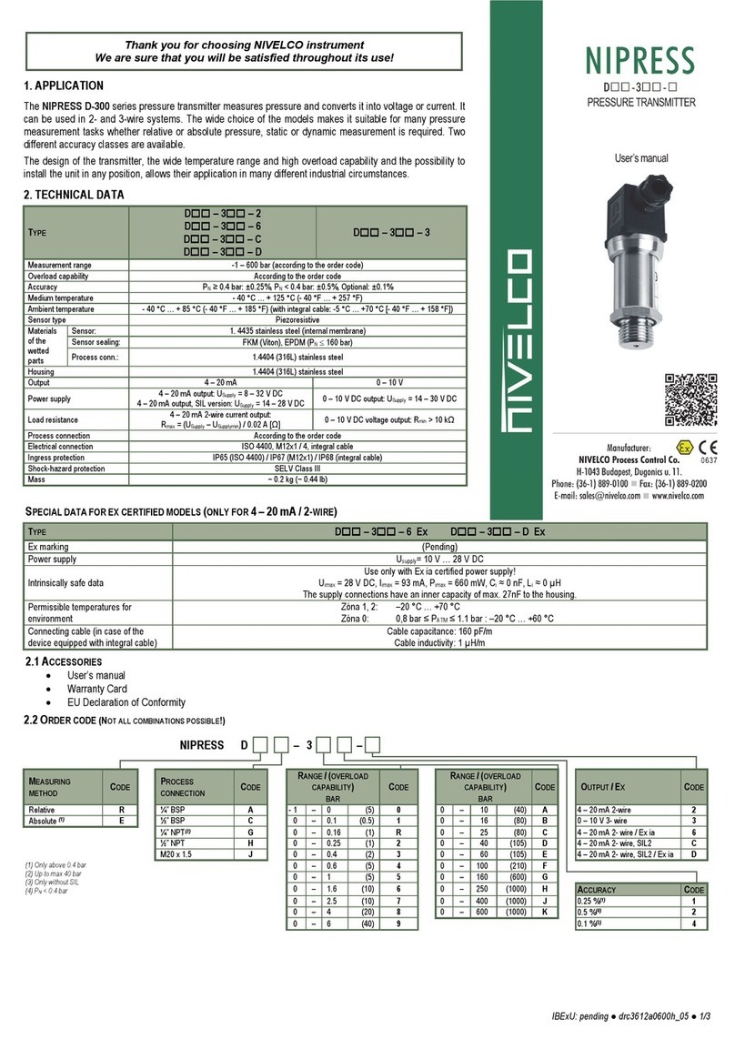
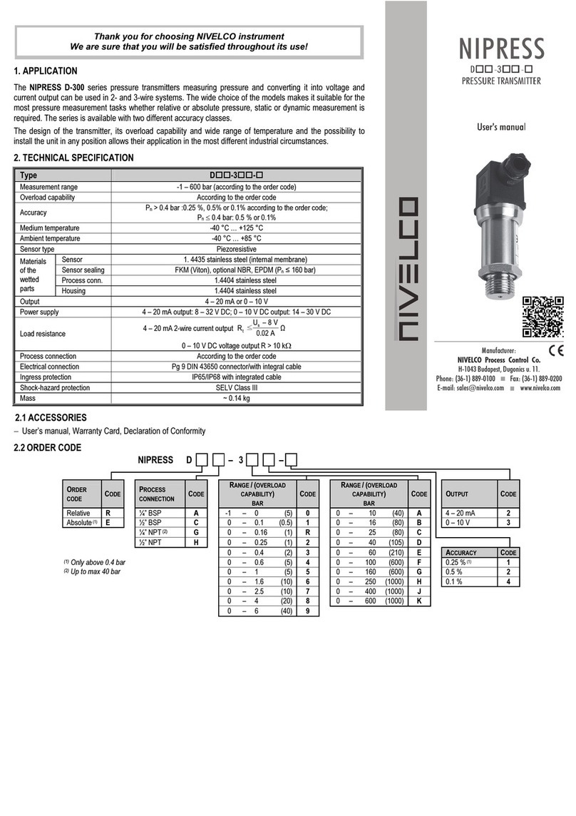
NIVELCO NIPRESS D 3 Series User manual

drc3612en607h ●1/3
Thank you for choosing NIVELCO instrument
We are convinced that you will be satisfied with our product!
1. APPLICATION
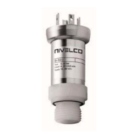
The NIPRESS D–300 series pressure transmitter measures pressure and converts it into voltage or current.
It can be used in 2- and 3-wire systems. The models' wide choice makes it suitable for many pressure
measurement tasks, especially for use in hydraulic applications with relative or absolute pressure, static or
dynamic measurement is required. Two different accuracy classes are available. The transmitter's design, the
wide temperature range, high overload capability, and the possibility of installing the unit in any position allow
their application in many different industrial circumstances.
Transmitters can be delivered with plug-in display UNICONT PLK–501 enabling on-site reading. Ex or SIL
versions are also available.
2. TECHNICAL DATA
Type D–3–2, –6, –C, –D D–3–3
Measurement range –1…600 bar (0…8700 psi) (according to the order code)
Overload capability According to the order code
Accuracy PN≥0.4 bar: ±0.25%, ±0.5%, Optional: ±0.1%, ±0.2%
Medium temperature –40…+125 °C (–40…+257 °F)
Ambient temperature(1) –40…+85 °C (–40…+185 °F) (with integral cable: –5…+70 °C [–40…+158 °F])
Materials
of the
wetted
parts
Sensor: 1.4435 stainless steel (internal membrane)
Sensor sealing: FKM (Viton), EPDM (PN160 bar) (PN≤2320 psi)
Process conn.: 1.4404 (316L) stainless steel
Housing 1.4404 (316L) stainless steel
Optional: 1.4301 (304) stainless steel
Output 4…20 mA 0…10 V
Power supply (USupply)(1) 8…32 V DC
SIL version: 14…28 V DC 14…30 V DC
Load resistance Rmax = (USupply – USupply min.)/0.02 A [Ω]Rmin = 10 k
Process connection According to the order code
Electrical connection ISO 4400, M12x1 / 4, integral cable
Ingress protection IP65 (ISO 4400) / IP67 (M12x1) / IP68 (integral cable)
Shock-hazard protection Class III (SELV)
Mass ~0.2 kg (~0.44 lb)
(1) For information of Ex certified devices, see Special data for Ex certified models chart
SPECIAL DATA FOR EX CERTIFIED MODELS (ONLY FOR 4…20 mA /2-WIRE)
Type D–3–6Ex, D–3–DEx
Ex marking II 1G Ex ia IIC T4 Ga, II 1D Ex ia IIIC T135°C Da
Ex reference document drc3612a0600h_07
Power supply 10…28 V DC
Intrinsically safe data Uimax = 28 V DC, Iimax = 93 mA, Pimax = 660 mW, Ci≈0 nF, Li≈0 µH
The supply connections have an inner capacity of max. 27 nF to the housing.
Permissible medium temperature,
atmospheric pressure
Zone 0: –20…+60 °C; 0.8 bar ≤PATM ≤1.1 bar
Zone 1, 2: –20…+70 °C
Connecting cable (in case of the device
equipped with integral cable)
Cable capacitance: 160 pF/m
Cable inductivity: 1µH/m
2.1 ACCESSORIES
-User’s manual
-Warranty Card
-EU Declaration of Conformity
2.2 ORDER CODE (NOT ALL COMBINATIONS POSSIBLE!)
NIPRESS D – 3 – *
Measuring method Code
Process
connection Code Range(1) / Nominal
pressure (bar) Code Range(1) / Nominal
pressure (bar) Code
Output / Ex Code
Relative R ¼" BSP A –1…0 / 5 0 0…10 / 40 A 4…20 mA, 2-wire 2
Absolute(2) E ½" BSP C 0…0.1 / 0.5 1 0…16 / 80 B 0…10 V, 3-wire 3
¼" NPT(3) G 0…0.16 / 1 R 0…25 / 80 C 4…20 mA, 2-wire / Ex ia(4) 6
½" NPT H 0…0.25 / 1 2 0…40 / 105 D 4…20 mA, 2-wire, SIL2(4) C
M20x1.5 J 0…0.4 / 2 3 0…60 / 210 E 4…20 mA, 2-wire, SIL2 / Ex ia(4) D
* Ex versions are marked "Ex" right after the type designation on the label.
(1)Custom measuring range, based on prior negotiations.
(2)pN≥0.4 bar
(3)max. 40 bar
(4)Ex or SIL versions are available upon special request.
(5) Not in combination with SIL
Note:
In case of non-standard applications, the sensor type, sealing and housing,
as well as the requirement for filling with food compatible oil has to be
specified in the order!
0…0.6 / 5 4 0…100 / 600 F
0…1 / 5 5 0…160 / 600 G
0…1.6 / 10 6 0…250 / 1000 H Accuracy Code
0…2.5 / 10 7 0…400 / 1000 J 0.25%(2) 1
0…4 / 20 8 0…600 / 1000 K 0.5% 2
0…6 / 40 9 0.2% 6
0.1%(5) 4
drc3612en607h ●2/3
2.3
D
IMENSIONS
DC–3–2, –3, –6
Normal version
DC–3–C, –D
SIL and SIL-Ex version
Transmitter +
PLK–501–2
Plug-in display
DA–3–DG–3–DH
–
3–
p
N
≤40 bar
p
N
≥60 bar
3. INSTALLATION
Due to its small size and weight the transmitter can be directly installed on tanks,
pipes, machines, etc. without any mounting aids.
To enable the safe replacement of the instrument during operation the use of closing
armature is recommended. A simple ball valve will be suitable for lower pressures
and for higher pressures (above 6 bar) a three-way blow-off needle-valve can be
suggested. With pressure measurements of medium with temperature over +75 °C
(+167 °F), the application of condensing device would protect the instrument against
overheating and extends its lifetime.
The temperature of the condensation in the condensing devices (in the water lodge)
is practically only +10…+20 C (+18…+36 °F) higher than the ambient temperature.
Using longer impulse tube its proper sloping for the necessary de-aerating and
emptying has to be ensured.
Measuring low pressure values in systems with substantial height difference
between the transmitter and place of measurement the hydrostatic pressure of the
medium in the impulse pipe should be taken into consideration. In case of outside
installation, the unit should be protected against rain or splash water, because
malfunction may occur if the connector’s screw is not tightened properly (i.e. not
appropriate sealing).
Installation position: The pressure transmitter has been calibrated in a vertical
position with the pressure port facing down. If this position changes during
installation, a slight deviation from the zero point may occur in the measured value.
3.1 I
NSTALLATION INSTRUCTION
The measured medium – depending on its type and properties, might be hazardous
to the installer. Therefore, the wear of appropriate protective clothing, gloves, and
goggles are recommended.
Be careful because the membrane is very vulnerable!
Torque should only be transferred to the hexagonal screw on the instrument body
(torque wrench). The cylindrical housing of the transmitter must not be gripped
and tightened with a pipe wrench!
The plug-in electric connector can be unplugged after releasing and removing its
fastening screw. The connection insert can be pushed out by a screw driver from
the direction of the screw.
Pushing the electric cable through the cable gland it can be connected to the
relevant points of the connector. Make sure that the cable gland and sealing plate
of the connector is tightened properly.
For the sake of noise suppression, the transmitter housing is grounded. If the
grounding of the appliance with the pressure transmitter is appropriate, no further
action will be needed, else, the grounding should be performed.
Installation steps:
Tightening torques:
¼" BSP: max. 5 Nm; ½" BSP: max. 10 Nm; ¾" BSP: max. 15 Nm;
1" BSP: max. 20 Nm; 1½" BSP: max. 25 Nm.
The specified tightening torques must not be exceeded!
Mounting steps for BSP thread connections according to DIN 3852:
Do not use any additional sealing material such as Teflon tape! Check if the O-ring
is undamaged, it has a flawless and clean surface and seats in the designated
groove properly. Screw the device into the corresponding thread by hand, and
tighten the parts with a suitable torque wrench.
If your device can be secured with a knurled ring, the pressure transmitter should
only be tightened by hand!
Mounting steps for NPT thread connections
Use a suitable sealant (e.g. PTFE tape). Turn the device by hand to the correct
thread and tighten it with an open-end torque wrench.
4. WIRING
Use a shielded and twisted multicore cable for the electrical connection. Electrically
connect the device according to the “Connection of ISO 4400 plug” figure. For
devices with cable gland, make sure that the external diameter of the cable used is
within the allowed clamping range! Once connected the wires, tighten the gland
screw firmly until the sealing is proper!
For the installation of a device with an integrated cable, the bending radiuses have
to comply with the following:
Cable without ventilation tube:
- static installation: 8-fold cable diameter,
- dynamic application: 12-fold cable diameter.
Cable with ventilation tube:
- static installation: 10-fold cable diameter,
- dynamic application: 20-fold cable diameter.
In case of devices with cable outlet and integrated ventilation tube, the PTFE filter
located at the cable end on the ventilation tube must not be damaged or missing!
2-wire current output
3-wire voltage output
Connection of integral cable

drc3612en607h ●3/3
Connection of ISO 4400 plug
Connection of M12x1 / 4 pin plug
4.1
E
XAMPLES OF ARRANGEMENTS
Wiring of 2-wire pressure transmitters
Wiring of 3-wire pressure transmitters
Wiring of 2-wire Ex ia pressure transmitters
5. SPECIAL CONDITIONS OF SAFE USE
Before turning on the device, make sure the installation is
complete, with no defects visible.
The device may only be used within the limitations specified
in the technical specifications.
The electrical connection of the device must be carried out in a way that the
IP20 ingress protection is always ensured!
Ex ia certified transmitters may only be operated in certified and approved
intrinsically safe Ex ia IIC circuits complying with the technical data and the
device’s explosion protection marking.
The metal housing of the device must be connected to the EP (equipotential)
network!
Attention! The devices may partially contain static charging capable plastic
components. The presence of electrostatic charges may cause a risk of spark
generation and ignition and therefore electrostatic charges must be
completely prevented!
Avoid friction on plastic surfaces!
Do not clean the device dry!
For example, use a wet duster!
6. TROUBLESHOOTING
Fault Possible causes Fault detection / remedy
No output signal
The Connection is
improper. Check the connections!
Broken conductor/wire. Check all wires with cable
tester!
Defective measuring
device (signal input).
Check the ampere meter (and
its fuse) and the analogue input
of the signal processing unit!
Analog output signal
too low:
Load resistance too high. Check the value of the load
resistance!
Defective energy supply.
Check the power supply and
power / current on the
transducer / transmitter!
Slight shift of the output
signal:
The diaphragm of the
sensor is severely
contaminated.
Cleaning with non-aggressive
cleaning solutions, soft brush
or sponge.
The diaphragm of the
sensor is calcified or
crusted.
It is recommended to clean the
device carefully to ensure all
the dirt is completely removed.
Large shift of the output
signal:
The diaphragm of the
sensor is damaged
(caused by overpressure
or mechanically).
Check the diaphragm of the
sensor, if it is damaged send
the device back to the
manufacturer!
7. MAINTENANCE AND REPAIR
The instrument does not require regular maintenance. The repair should only be
carried out at NIVELCO's premises.
When disconnecting the device, it must always be done in depressurized and
disconnected state! Drain the medium before disconnecting the device.
If necessary, clean the diaphragm carefully with non-aggressive cleaning solution,
soft paint-brush or sponge. Improper cleaning may cause the irreparable damage of
the diaphragm. For this reason, never use sharp objects or pressurized air for
cleaning the diaphragm.
Before returning your device for repair, it has to be cleaned carefully,
neutralize/decontaminate the parts wet from the medium might contain harmful
substances. Our appropriate form (Returned Equipment Handling Form) must be
enclosed after downloaded from our homepage www.nivelco.com. You should
dispatch the device with a declaration of decontamination. In the declaration, you
have to provide a statement that the decontamination process is completed, and,
the device is clean and free from harmful material and there is no hazardous
substance on it.
8. STORAGE CONDITIONS
Storage temperature: –40…+100 °C (–40…+212 °F)
drc3612en607h
December 2020
NIVELCO reserves the right to change technical data without notice!

Other NIVELCO Transmitter manuals

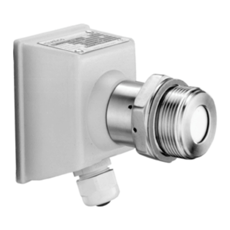
NIVELCO THERMOCUT TT Series Owner's manual

NIVELCO

NIVELCO THERMOCUT TT Series Owner's manual

NIVELCO MicroTREK Assembly instructions

NIVELCO

NIVELCO MicroTREK Assembly instructions

NIVELCO EasyTREK SP-300 Assembly instructions

NIVELCO

NIVELCO EasyTREK SP-300 Assembly instructions

NIVELCO NIVOPRESS DT 1 Series Assembly instructions

NIVELCO

NIVELCO NIVOPRESS DT 1 Series Assembly instructions

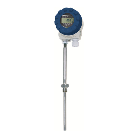
NIVELCO THERMOCONT TT Series Assembly instructions

NIVELCO

NIVELCO THERMOCONT TT Series Assembly instructions

NIVELCO EchoTREK S-300 Owner's manual

NIVELCO

NIVELCO EchoTREK S-300 Owner's manual

NIVELCO Nivotrack MI-5 Series Owner's manual

NIVELCO

NIVELCO Nivotrack MI-5 Series Owner's manual

NIVELCO NIPRESS DD-6 Seies User manual

NIVELCO

NIVELCO NIPRESS DD-6 Seies User manual

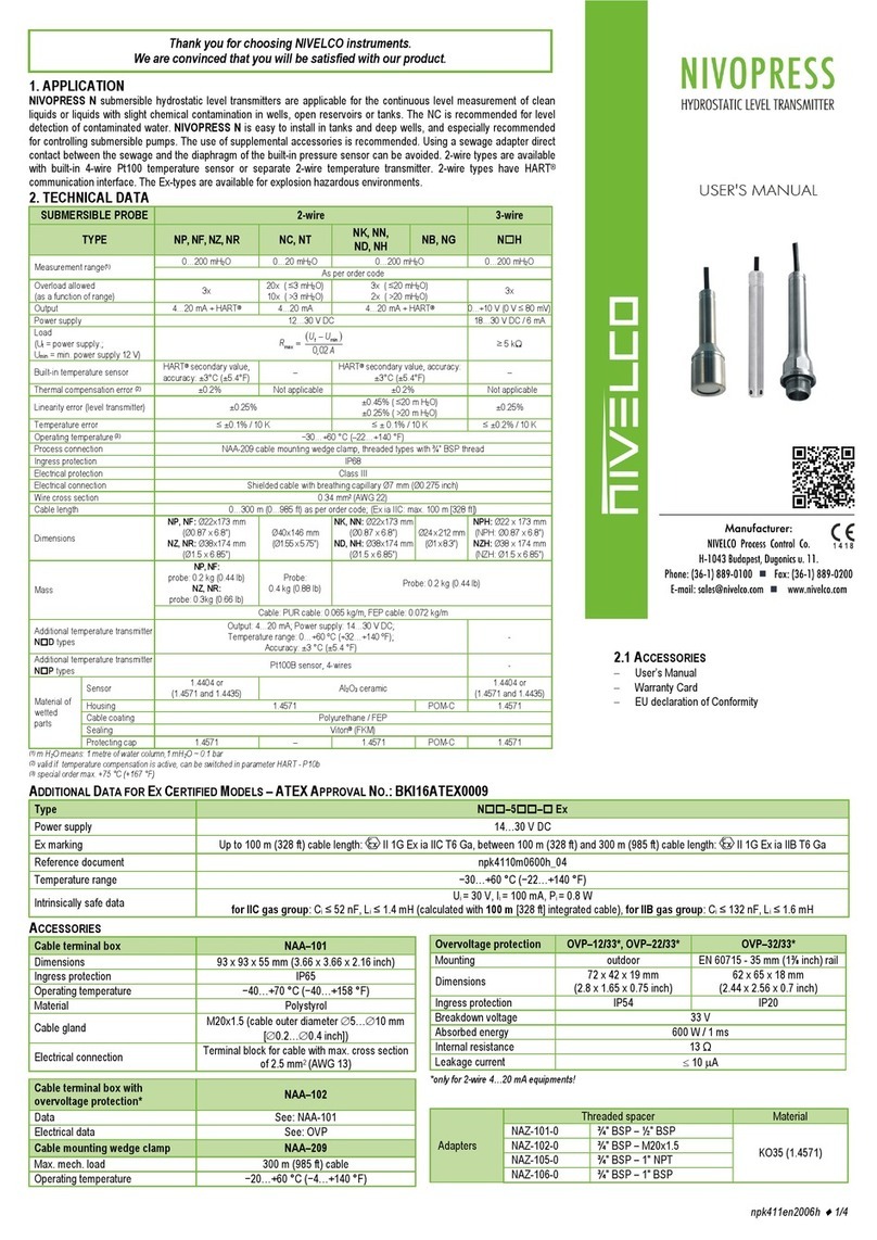
NIVELCO NIVOPRESS NT Series User manual

NIVELCO

NIVELCO NIVOPRESS NT Series User manual

NIVELCO EasyTREK SC-300 Series User manual

NIVELCO

NIVELCO EasyTREK SC-300 Series User manual

NIVELCO NIPRESS DD-400 User manual

NIVELCO

NIVELCO NIPRESS DD-400 User manual

NIVELCO NIPRESS D-A00 Series Owner's manual

NIVELCO

NIVELCO NIPRESS D-A00 Series Owner's manual

NIVELCO NIPRESS D-300 Series User manual

NIVELCO

NIVELCO NIPRESS D-300 Series User manual

NIVELCO EchoTREK S-300 User manual

NIVELCO

NIVELCO EchoTREK S-300 User manual

NIVELCO N H Series User manual

NIVELCO

NIVELCO N H Series User manual

NIVELCO EasyTREK SP-500 Pro Assembly instructions

NIVELCO

NIVELCO EasyTREK SP-500 Pro Assembly instructions

NIVELCO PiloTREK W-200 Owner's manual

NIVELCO

NIVELCO PiloTREK W-200 Owner's manual

NIVELCO THERMOPOINT TM-500 Owner's manual

NIVELCO

NIVELCO THERMOPOINT TM-500 Owner's manual

NIVELCO NIPRESS D-300 Series User manual

NIVELCO

NIVELCO NIPRESS D-300 Series User manual

NIVELCO EchoTREK ST-400 Series Assembly instructions

NIVELCO

NIVELCO EchoTREK ST-400 Series Assembly instructions

NIVELCO NIPRESS D 9 Series User manual

NIVELCO

NIVELCO NIPRESS D 9 Series User manual

NIVELCO PiloTREK 2-wire Assembly instructions

NIVELCO

NIVELCO PiloTREK 2-wire Assembly instructions

NIVELCO NIVOCAP C-200 Owner's manual

NIVELCO

NIVELCO NIVOCAP C-200 Owner's manual

NIVELCO EasyTREK SCD-34 4 Series Assembly instructions

NIVELCO

NIVELCO EasyTREK SCD-34 4 Series Assembly instructions

Popular Transmitter manuals by other brands

HETRONIC NOVA Series user manual

HETRONIC

HETRONIC NOVA Series user manual

IMI SENSORS HT640B01 Installation and operating manual

IMI SENSORS

IMI SENSORS HT640B01 Installation and operating manual

Javad TRIUMPH-1 Configuration Example

Javad

Javad TRIUMPH-1 Configuration Example

DeviceGate Technology BT-Pusher PRO+ user guide

DeviceGate Technology

DeviceGate Technology BT-Pusher PRO+ user guide

Temposonics LP Series Operation manual

Temposonics

Temposonics LP Series Operation manual

Honeywell XNX Technical manual

Honeywell

Honeywell XNX Technical manual

DELTA DORE TYDOM 2.0 installation guide

DELTA DORE

DELTA DORE TYDOM 2.0 installation guide

Linear Multi-Code 3089 installation instructions

Linear

Linear Multi-Code 3089 installation instructions

Akerstroms REMOTUS BC8518 DRIVING INSTRUCTION

Akerstroms

Akerstroms REMOTUS BC8518 DRIVING INSTRUCTION

Baker Hughes XMTC user manual

Baker Hughes

Baker Hughes XMTC user manual

GF Signet 8850-3 manual

GF

GF Signet 8850-3 manual

Emerson Rosemount 8750W Reference manual

Emerson

Emerson Rosemount 8750W Reference manual

Inovonics EN1702 installation instructions

Inovonics

Inovonics EN1702 installation instructions

RC System SENSMART 2000 user manual

RC System

RC System SENSMART 2000 user manual

Matchmaster 20MM-LT06L operating manual

Matchmaster

Matchmaster 20MM-LT06L operating manual

RKI Instruments 65-2443-100 Operator's manual

RKI Instruments

RKI Instruments 65-2443-100 Operator's manual

Vaisala HUMICAP HMD70U operating manual

Vaisala

Vaisala HUMICAP HMD70U operating manual

Spektrum SPMVT1000 manual

Spektrum

Spektrum SPMVT1000 manual

manuals.online logo
manuals.online logoBrands
  • About & Mission
  • Contact us
  • Privacy Policy
  • Terms and Conditions

Copyright 2025 Manuals.Online. All Rights Reserved.