MiiS Horus+ EOC 100 User manual

Horus+Scope
EOC 100 Digital Otoscope
User Manual
DOC. No. 2014.02-A
Copyright@2014 MiiS Inc.
All right reserved.

1. Category 1
2. Symbols 2
3. Warnings and Cautions 3
4. Intended for Use 8
5. User Interface 9
6. Operating Instructions 11
7. Battery Charging and Photo
Transferring 12
8. Battery Replacement 13
9. Cleaning and Disinfection 14
10. Operation Environment 15
11. Environment for Storage and
Transportation 15
12. Technical Description 16
13. Liability 17
14. Environment 18
15. Standards 19

1
1. Category
Model Name MiiS Horus+ Scope EOC 100
Product Name Digital Otoscope
Accessory 1.Baery
2. Disposable Specula
a.) adult x 8
b.) pediatric x 8
3. Power Adapter
4. USB Cable
5. AV Cable

2 3
2. Symbols
Cauonmustbetaken.Readuser’smanualbeforeuse.
TypeBF-Indicatesthedeviceisclassifiedasadevice
with a Type BF applied part.
Theoperatorisadvisedtoreadtheinstructionsof
user’smanual.
Manufacturer.
DateofManufacture.
CEmark.
EuropeanAuthorizedRepresentave.
This product is a rechargeable internal Class II power
supply.
3. Warnings and Cautions
NOTE
Priortoinstallationandstart-upofthedevice,carefullyreadthe
instruconsprovidedherein!Aswithalltechnicaldevices,theproper
functionandsafetyoperationofthis devicedependontheuser’s
compliancewiththesafetyrecommendaonswhicharepresentedin
theseoperanginstrucons.Donotaempttoopenthecoverofthe
product,soastoavoidmalfunconofproduct.
CAUTION
Alwaysuse the deviceinaccordancewiththedirecons
andrecommendaonscontainedinthisUserManual.
Operatethedevice,pleasetakenotethatopticallens
donottouchtheeyesornoseofpaent.Avoidharmto
paent.
Topreventreorelectricalshock,donotexposethese
appliances to rain or moisture.
Thisdeviceisnotwaterproof.Iftheopticallensand
controlunitgetwet;donotaempttodrywithaheater,
microwave,autoclaveorUVlight.

4 5
Avoidsubjecngthedevicetovibraonorshock.When
theproductisnotinuse,please disconnectthepower
plugandkeepitinasafeplace.
Avoidusingthedeviceinadustyenvironment,andkeep
thepowercordawayfromanyheatsource.
Beforeoperaon,pleasemakesuretheappearanceisnot
damagedorbroken.Iftherearebreaksinthedevicecov-
erorothervisualdefects,pleasecontactmanufactureror
manufacturerceredservicefacility.
Pleasedonotchargethebaerywhenthedeviceisoper-
ated by the user.
OnlyuseLi-ionBaery3.7V@2600mAhwhichshallbe
providedbythemanufacturerordistributors.Thebaery
hasdesignedtheproteconcircuit.Toensurethesafety
oftheproductoperaon,ifthebaeryreacheslifeme
orfailure,pleasecontactthemanufacturerordistributor
tobuythesparebaery.
IfyoupurchasedifferentmemorycapacityofMicroSD
Card,mustbeprecededformattoFAT32.
Theeyecan’tbe exposedtotheilluminaonlightofthe
productatoperaon.
ReplacethedisposablespeculaofHorus+ScopeEOC100,
DigitalOtoscope,beforeeachuseforanewpaent.
GentlyinsertthespeculaofHorus+ScopeEOC100into
earcanal.Tokeepasafetydistancebetweenthespecula
andtympanicmembrane.Donotmakethespeculacon-
tactwithear’stympanicmembrane.
Nomodificationofthisdeviceisallowed.Theperfor-
mancewouldbechangedifmodifythisdevicebyuser.
Modicaontothisdevicemaycausehazardousradiaon
exposure.
Thisdevicehasbeentestedandfoundtocomplywiththe
limitsformedicaldevicestotheIEC60601-1-2:2007.
These limits are designed to provide reasonable protec-
onagainstharmfulinterferenceinastandardmedical
installaon.Ifthisdevicedoescauseharmfulinterference
tootherdevices,whichcanbedeterminedbyturning
thesystemoandon,theuserisencouragedtotryto
correcttheinterferencebyoneormoreof thefollowing
measures:
• Reorientorrelocatethereceivingdevice
• Increasetheseparaonbetweenthe systemand
other devices.
• Connectthedevicetoan outletonacircuitdif-
ferentfromthattowhichtheotherdevice(s)are
connected.

6 7
• Consultthemanufactureroreldservicetechni-
cianforhelp.
The International Electrotechnical Commission sets the
essentialrequirementsforelectricalandelectronic
equipmentthatmaydisturb,orbedisturbedby,other
equipment.
The device complies with these requirements as shown
inthetablesin“15.(1)EMC(ElectromagnecCompabil-
ity)”(Page13-16).Followtheguidanceinthetablesfor
useofthedeviceinanelectromagnecenvironment.
Duringinstallaonand operaonofthedevice,observe
thefollowinginstructionsaboutEMC(electromagnetic
compability):
• Do not use the device simultaneously with other
electronic equipment to avoid
• electromagnecinterferencewiththeoperaonof
the device.
• Donotuseorstackthedevicenear,on,orunder
other electronic equipment to avoid electromag-
necinterferencewiththeoperaonofthedevice.
• Do not use the device in the same room as other
electronicequipmentsuchaslife-support equip-
ment,equipmentthathasmajoreffectsonthe
lifeofthepaentandresultsoftreatment,orany
other measurement or treatment equipment that
involves small electric current.
• Do not use the system with portable and mobile
radiofrequencycommunicaonsystemsbecause
thatmayhaveanadverseeectonoperaonof
the device.
• Do not use cables or accessories that are not
speciedforthedevicebecausethatmayincrease
theemissionofelectromagneticwavesfromthe
deviceanddecreasetheimmunityofthedeviceto
electromagnecdisturbance.
• Donottouchlensconnecngpins ofcontrolunit,
orsignalpadoflenseswithoutspecialprecauons.
Usersareresponsibleformanagingcapturedimagedata.
Manufacturerwillnotassumeanyresponsibilityforloss
ofdata.

8 9
4. Intended for Use
EOC 100 is a digital hand-held otoscope used to record digital photo-
graphsandvideoofthehumanear’scanalandtympanicmembrane.
EOC100canalsobe usedatgeneralInspeconofthroatandnasal
cavity and capture the photographs and video.
5. User Interface
Powerbuon
Interfaceof
specula
Focus wheel
Baerycover
Insuaonport

10 11
6. Operating Instructions
SD Card slot
AV out
Mini USB out
Attaching / removing
direconofthespecula
13:24:122014/04/16
5B 1234M
1
2
3
4
5
6
10
11
7
8
9
1.OperaonMode:
Photo
Video
Display
2. Brightness indicator
3. Free memory
ofSDCard
4. Power indicator
5. Date indicator
6.Timeindicator
7.Brightnessdecreasing/
Funconselecon
8. MENU
9. Brightness increasing/
Funconselecon
10.StatusIndicator:
BlueLED-NormalOperaon
Orange LED- In charging
11.CaptureBuon

12 13
7. Battery Charging and Photo
Transferring
Baery Charging:
Step1. Connect the EOC 100 and power adapter via USB cable.
Step2. Insertthepoweradapterintothewallplugforcharging.
Photo Transferring:
Connect the EOC 100 and computer via USB cable. At normal situa-
on,EOC100becomesastandardstoragedevice,usercanreviewor
copythephotosfromthisdevicetothecomputer.
NOTE
EOC 100 can also operate at “UVC” mode. It means the pictures can
beshownatLCDpanelofEOC100andthescreenofthecomputerif
EOC 100 is connected to computer via USB cable.
Userwanttooperateat“UVC”mode,pleaseenterthemenutoen-
ablethisfuncon.
8. Battery Replacement
BaeryReplacement
Openthebaerycoverbydiggingoutthegapintheboomofbat-
terycoverwithangerorsomethingpointed.
• Tiltthebaerycoverandremovethebaerycoverbyliingit
up.
• Removethe originalbaeryandreplaceanewbaeryalong
thecorrectdirecon.
• Placethebaerycoverandsecureitinplace.

14 15
9. Cleaning and Disinfection
The device is a precision photoelectronic instrument that shall be
handledwithspecificcare.Pleasenotefollowingcleaninginstruc-
ons:
• Powerodevicebeforecleaningit.
• Disinfecttheproductwiththesoftclothwithalcohol(70%
ethyl alcohol).
• Itisrecommendedtocleantheopcallenswithcleaningcloth
orlenscleaningssuesuchasTHORLABInc.,(www.thorlabs.
com) Lens Cleaning Tissue.
Ifthereplacementfornewdisposablespecula,pleasecontactwith
manufactureroryourownretailer.
NOTE
The device is not intended to be sterilized
10. Operation Environment
• Ambienttemperature: 0°Cto+35°C
• Relavehumidity: 10%to80%
• Atmosphericpressure: 700hPa~1060hPa
11. Environment for Storage and
Transportation
• Ambienttemperature: -10°Cto+40°C
• Relavehumidityrange: 10%to95%
NOTE
Itisrecommendedtoremovethebaeryifthedeviceisstoredover2
weeks.

16 17
12. Technical Description
• FocusRange 25~100mm(Typical)
• Dimension 180x70x70mm3(Typical)
• Weight 200Grams(Typical)
• Camera/Video NaturalWhiteLightEmingDiode(LED)
Focus: Manual Focus
CameraResoluon: 1920 x 1080 pixels
Screen: TFT-LCD
ImageFormat: JPEG(Photograph)and
H.264(Video)
Interface: MiniUSB,AVoutport
FileTransfer: Mini USB Port to PC
DynamicVideoOutput: CompositeAVout,orUSB
livevideoenablefromUSB
port
Filestorage: SDCard,default8GB.Sup-
ports 2G to 32GB by FAT32
Format
PowerSource: RechargeableLithiumBat-
tery3.7V/2600mAh
ExternalPower: Source: 100~240VAC,
50/60Hz
Poweradapteroutputspec: 5VDC,1.2A
Operangme: 3hoursat2.5Wattcondi-
on
Chargingme: 5 hours
Expectedservicelife:
(denedbymanufacturer)
5yearsfromthedateof
inialoperaon
*Proper maintenance is
necessary
13. Liability
Manufacturerconsidersitselfresponsiblefortheeffectsonsafety,
reliabilityandperformanceofthedeviceonlyif:
• Assemblyoperations,extensions,re-adjustments,modifica-
onsorrepairsarecarriedoutbypersonsauthorized.
• Theelectricalinstallaonof the relevantroomcomplieswith
the requirements.
• Theequipmentisusedinaccordancewiththeseinstrucons
foruse.

18 19
14. Environment
• Follow the local governing ordinances and recycling plans re-
gardingdisposalorrecyclingofdevicecomponents.Especially
whendisposingofthelithiumionbaery,circuitboard,plasc
partsthatcontainbrominatedameretardant,LCD,orpower
cord,besuretofollowthelocalgoverningordinances.
• Follow the local governing ordinances and recycling plans
whendisposingofthecircuitboardwiththelithiumbaery.
Inappropriate disposal may contaminate the environment.
• Whendisposingofpackingmaterials,sortthembymaterial
andfollowlocalordinancesandrecyclingregulaons.
• Inappropriate disposal may contaminate the environment.
• Whendisposingofeyecup,followthedisposalproceduresfor
medicalwastesuchasneedles,infusiontubes,metalinstru-
mentsforsurgeryasspeciedbyyourmedicalfacilitytoavoid
infeconoutsidethefacilityandenvironmentalpolluon.
15. Standards
Electricalsafety IEC60601-1:2005
(EN60601-1:2006)
EMC and regulatory
compliance
IEC60601-1-2:2007
(EN60601-1-2:2007)
• Equipmentconnectedtotheanalogordigitalinterfacesmust
becertifiedaccordingtotherepresentativeappropriate
nationalstandards(suchasEN60601-1andIEC60601-1).
Furthermore,allconguraonsshallcomplywiththesystem
standardIEC60601-1.Anyonewhoconnectsaddionalequip-
menttothesignalinputpartorsignal output partcongures
amedicalsystem,andisthereforeresponsiblethatthesystem
complieswiththerequirementsofthesystemstandardIEC
60601-1.Ifindoubt,consultthetechnicalservicedepartment
ofyourlocalrepresentave.
EMC (Electromagnec Compability)
ThedevicecomplieswiththeInternaonalElectrotechnicalCommis-
sionstandards(IEC6060112:2007)forelectromagneccompability
aslistedinthetablesbelow.Followtheguidanceinthetablesforuse
ofthedeviceinanelectromagnecenvironment.

20 21
EMC (IEC 60601 1 2: 2007)
Guidance and manufacturer’s declara-
on electromagnec emissions
Thedeviceisintendedforuseintheelectromagnecenviron-
mentspeciedbelow.Thecustomerortheuserofthedevice
should assure that it is used in such an environment.
Emissions test Compliance Electromagnecenvi-
ronment guidance
RFemissions
CISPR11
Group 1 Thedeviceuses RFenergyonly
foritsinternalfunction.There-
fore,itsRFemissionsareverylow
andarenot likelytocause any
interferenceinnearbyelectronic
equipment.
RFemissions
CISPR11
Class B Thedeviceissuitableforusein
allestablishments,includingdo-
mescestablishmentsandthose
directly connected to the public
lowvoltagepowersupplynetwork
thatsuppliesbuildings usedfor
domescpurposes.
Harmonic emissions
IEC6100032
*1
Voltageuctuaons/Flick-
eremissionsIEC6100033
*2
*1Fortheregionswheretheratedvoltageis220Vorgreater,thisdevicecomplies
withclassA.Fortheregionswheretheratedvoltageis127Vorless,thisstandard
is not applicable.
*2Fortheregionswheretheratedvoltageis220Vorgreater,thisdevicecomplies
withthisstandard.Fortheregionswheretheratedvoltageis127 Vorless,this
standard is not applicable.
Guidance and manufacturer’s declara-
on electromagnec immunity
Thedeviceisintendedforuseintheelectromagnecenviron-
mentspeciedbelow.Thecustomerortheuserofthedevice
should assure that it is used in such an environment.
Immunity test IEC60601
test level
Compli-
ance level
Electromag-
necenviron-
ment guidance
Electrostac
Discharge(ESD)
IEC6100042
±6kVcontact
±8kVair
±6kVcontact
±8kVair
Floor should be
wood,concrete
orceramicle.If
oorsarecovered
withsynthecma-
terial,therelave
humidity should
beatleast30%.
Electricalfast
transient/burst
IEC6100044
±2kV
forpower
supply lines
±1kV
forinput/
output lines
±2kV
forpower
supply lines
±1kV
forinput/
output lines
Mains power
quality should be
thatofatypical
commercial or hos-
pital environment.
Surge
IEC6100045
±1kV
dierenalmode
±2kV
common mode
±1kV
dierenalmode
±2kV
common mode
Mains power
quality should be
thatofatypical
commercial or hos-
pital environment.
22 23
Voltage,dips,short
interruponsand
voltagevariaons
on power supply
input lines
IEC61000411
<5%U
T
(>95%dipinU
T
)
for0.5cycle
40%U
T
(60%dipinU
T
)
for5cycles
70%U
T
(30%dipinU
T
)
for25cycles
<5%U
T
(>95%dipinU
T
)
for5sec
<5%U
T
(>95%dipinU
T
)
for0.5cycle
40%U
T
(60%dipinU
T
)
for5cycles
70%U
T
(30%dipinU
T
)
for25cycles
<5%U
T
(>95%dipinU
T
)
for5sec
Mains power qual-
ity should be that
ofatypicalcom-
mercial or hospital
environment.Ifthe
userofthedevice
requiresconnued
operaonduring
power mains
interrupons,itis
recommended that
the device be pow-
eredfromanunin-
terrupblepower
supplyorabaery.
Powerfrequency
(50/60Hz)mag-
neceld
IEC6100048
3 A/m 3 A/m Powerfrequency
magnecelds
should be at levels
characteriscof
atypicallocaon
in a typical com-
mercial or hospital
environment
NOTE:U
T
isthea.c.mainsvoltagepriortoapplicaonofthetestlevel.
Guidance and manufacturer’s declara-
on electromagnec immunity
Thedeviceisintendedforuseintheelectromagnecenviron-
mentspeciedbelow.Thecustomerortheuserofthedevice
should assure that it is used in such an environment.
Immu-
nity test
IEC60601
test level
Compli-
ance level
Electromagnecenviron-
ment guidance
Con-
ductedRF
IEC
6100046
RadiatedRF
IEC
6100043
3 Vrms
150kHzto
80 MHz
3 V/m
80 MHz to
2.5 GHz
3 Vrms
(V1=3)
3 V/m
(E1=3)
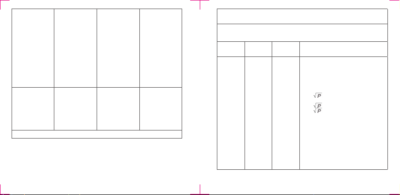
PortableandmobileRFcommunicaons
equipment should be used no closer to
anypartofthedevice,includingcables,
thantherecommendedseparaondis-
tancecalculatedfromtheequaonappli-
cabletothefrequencyofthetransmier.
Recommended separaon distance
d=1.2 150kHzto80MHz
d=1.2 80 MHz to 800 MHz
d=2.3 800 MHz to 2.5 GHz
where Pis the maximum output
powerrangofthetransmierin
was(W)accordingtothetransmier
manufactureranddistherecommended
separaondistanceinmeters(m).
FieldstrengthsfromxedRFtransmiers,
asdeterminedbyanelectromagnecsite
survey,ashould be less than the compli-
ancelevelineachfrequencyrange.b

24 25
Interferencemayoccurinthe
vicinityofequipmentmarked
withthefollowingsymbol:
NOTE1:At80MHzand800MHz,thehigherfrequencyrangeapplies.
NOTE2:Theseguidelinesmaynotapplyinallsituaons.Electromagnecpropaga-
onisaectedbyabsorponandreeconfromstructures,objectsandpeople.
aFieldstrengthsfromxedtransmiers,suchasbasestaonsforradio
(cellular/cordless)telephonesandlandmobileradios,amateurradio,AM
andFMradiobroadcastandTVbroadcastcannotbepredictedtheorecally
withaccuracy.ToassesstheelectromagnecenvironmentduetoxedRF
transmiers,anelectromagnecsitesurveyshouldbeconsidered.Ifthe
measuredeldstrengthinthelocaoninwhichthedeviceisusedexceeds
theapplicableRFcompliancelevelabove,thedeviceshouldbeobservedto
verifynormaloperaon.Ifabnormalperformanceisobserved,addional
measuresmaybenecessary,suchasreorienngorrelocangthedevice.
bOverthefrequencyrange150kHzto80MHz,eld
strengths should be less than 3 V/m.
Recommended separaon distances between portable and
mobile RF communicaons equipment and the device
Thedeviceis intendedforuseinanelectromagnecenvironmentinwhichradi-
atedRFdisturbancesarecontrolled.Thecustomerortheuserofthedevicecan
helppreventelectromagnecinterferenceby maintainingaminimumdistance
betweenportableandmobileRFcommunicaonsequipment(transmiers)and
thedeviceasrecommendedbelow,accordingtothemaximumoutputpowerof
thecommunicaonsequipment.
Ratedmaximum
output power
oftransmier
W
Separaondistanceaccording
tofrequencyoftransmier
m
150kHzto80MHz
d=1.2
80 MHz to 800
MHz
d=1.2
800 MHz to 2.5
GHz
d=2.3
0.01 0.12 0.12 0.23
0.1 0.38 0.38 0.73
1 1.2 1.2 2.3
10 3.8 3.8 7.3
100 12 12 23
Fortransmiersratedatamaximumoutputpowernot listedabove,the recom-
mendedseparaondistancedinmetres(m)canbeesmatedusingtheequaon
applicabletothe frequencyofthetransmier,wherePis the maximum output
powerrangofthetransmierinwas(W)accordingtothe transmiermanu-
facturer.

26 27
NOTE1:At80MHzand800MHz,theseparaondistanceforthehigherfrequency
range applies.
NOTE2:Theseguidelinesmaynotapplyinallsituaons.Electromagnecpropaga-
onisaectedbyabsorponandreeconfromstructures,objectsandpeople.
MedimagingIntegratedSoluonInc.
1F,No.7,R&DRdII,HsinchuSciencePark,
Hsinchu,TAIWAN30076,R.O.C
Obelis S.A.
Bd.GeneralWahis53,1030,Brussels,Belgium
Issueddate:July23,2014
Please visit www.miis.com.twformoreinformaon.
Table of contents
Other MiiS Medical Equipment manuals


Popular Medical Equipment manuals by other brands


YIMI Life
YIMI Life YM201 user manual

Integra
Integra MAYFIELD Spine Table Adapter A2600R instruction manual

Henry Schein
Henry Schein COLPOSCOPE I user manual

Enabling Devices
Enabling Devices 705 user guide

schupp
schupp Trendino 139235 Instructions for use

Click Medical
Click Medical RevoLock quick start guide


