Bodypoint Moduform Dynamic Arm Support AS001 User manual

BPI118-en2023.5
© 2022 Bodypoint, Inc. All rights reserved.
558 1st Ave. S., #300, Seattle, WA 98104, USA l 206.405.4555 l 800.547.5715 l www.bodypoint.com
Medical
Device
Bodypoint Europe BV
Kerkstraat 29
7396 PG Terwolde
The Netherlands
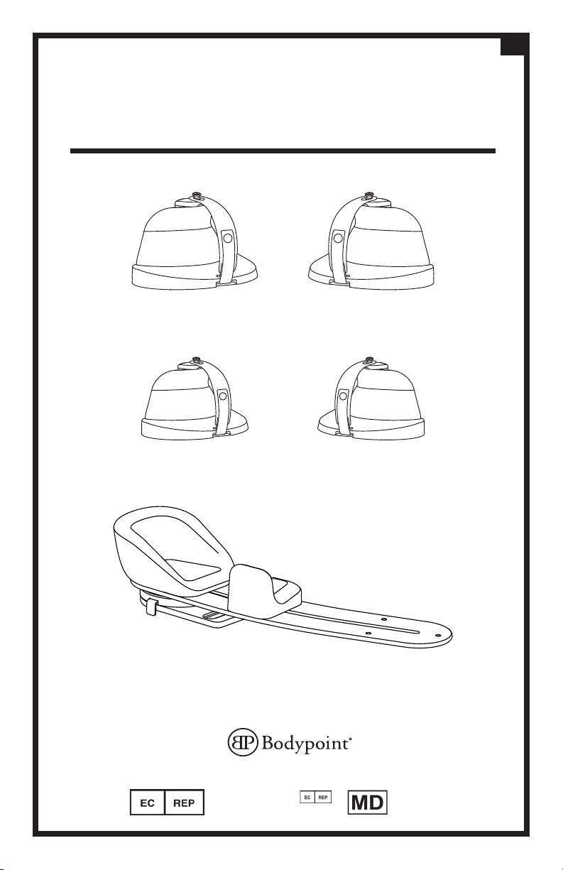
AS115L AS115R
AS116L AS116R
AS200R
ART NOS.: AS001
Moduform Dynamic Arm Support
Assessment Kit Contents
en

M6x20mm
M5x35mm
M6x35mm
M5
M6
M5
M6 X4
AS120
AS118
Ø22/25mm [7/8”/1”]
AS119
Ø19mm [3/4”]

© 2022 Bodypoint, Inc. All rights reserved.
BPI116-en2022.4
Medical
Device
Bodypoint Europe BV
Kerkstraat 29
7396 PG Terwolde
The Netherlands
558 1st Avenue South, #300, Seattle, WA 98104, USA
206.405.4555 l 800.547.5715 l www.bodypoint.com
INTENDED USE
:
The Moduform Dynamic Arm Support is a dynamic, mobile support for the elbow, forearm, and
hand that attaches to a manual or power wheelchair. It provides upper extremity support, functional
dynamic range of motion at the shoulder, and an innovative, exible hand support that promotes
hand function and helps to minimize exor tone and contractures.
This product includes modular components that can be adjusted for a customized orthotic t. A
pivot mechanism allows users to exercise the shoulder in a functional, dynamic range of motion.
The exible hand support helps to position the wrist, hand and ngers in neutral alignment and
minimize exor tone and contractures.
This product is designed to be mounted on a variety of wheelchair models with height adjustable
armrests and can be easily removed for transfers by utilizing the quick-release function. To ensure
the best clinical outcome, users should consult with a qualied healthcare professional before
using the product.
These instructions provide important information for the safe use and maintenance of
Bodypoint® Arm Supports. Give these instructions to the user or their caregiver.
INSTALLATION AND USER’S INSTRUCTIONS
ART NOS.: AS201L, AS201R, AS202L, AS202R, AS200L, AS200R
Moduform Dynamic Arm Support
en

PERIODIC SAFETY AND PERFORMANCE CHECKS:
To ensure user safety, this product must be checked periodically for function and signs of wear. If
the product does not function correctly or if signicant wear is found in the parts, stop using it and
contact your supplier for qualied repair or replacement by Bodypoint®. Under no circumstance
should this product be altered or repaired by unqualied persons.
CLEANING:
This product can be cleaned by wiping with disinfectant or a cloth soaked in warm water and soap.
Dry with a towel or air dry. A mild disinfectant can be applied to the surface. For cleaning the Hand
Strap, machine wash, hot, 60°C (140°F). Do not bleach. Tumble dry, low temperature, or drip dry.
Do not iron.
SCRAP/DISPOSAL:
This product is made of materials which can be disposed of safely without special precautions at
the end of its useful life.
WARRANTY:
This product carries a limited lifetime warranty against defects in workmanship and materials
arising under normal use by the original consumer. Contact your supplier or Bodypoint® for
warranty claims. For more information on Bodypoint® products and information on distributors
outside the USA go to www.bodypoint.com.
regular pressure relief activities and skin
integrity checks. If increased skin redness or
irritation occurs, discontinue use and consult
your qualified healthcare professional.
WARNING! Always monitor the user when
the Pivot Plate is unlocked to rotate. The
Pivot Plate should always be locked when
driving the wheelchair or transporting it in
a vehicle to prevent damage or injury that
could result from striking doorways or other
obstacles near the side of the chair.
WARNING! When mounting, check that
the Arm Support is securely locked into the
Quick-Release Adapter Plate. The installer
should hear an audible “click” sound.
WARNING! If a serious incident occurs
related to the use of this product, it should
be reported to the manufacturer (Bodypoint,
Inc.) and the local Competent Authority.
WARNING! This product should be
installed and fitted by a qualified rehab
technician.
WARNING! This product should only be
used for positioning a person’s arms in a
wheelchair. The misuse of this product is
unauthorized and unsafe.
WARNING! The user’s arm must be
positioned properly in the Arm Support. A
poorly adjusted Arm Support could allow
the user’s arm to slip out and dislocate the
shoulder or worsen hand flexor tone. Have
your therapist or technician demonstrate its
proper adjustment and use.
WARNING! If the user’s physical or
cognitive abilities prevent them from safely
operating this product, a caregiver must be
always present during its use. Ensure that all
caregivers know how to correctly operate
the product.
WARNING! This product may change
the way a person sits. Continue to practice
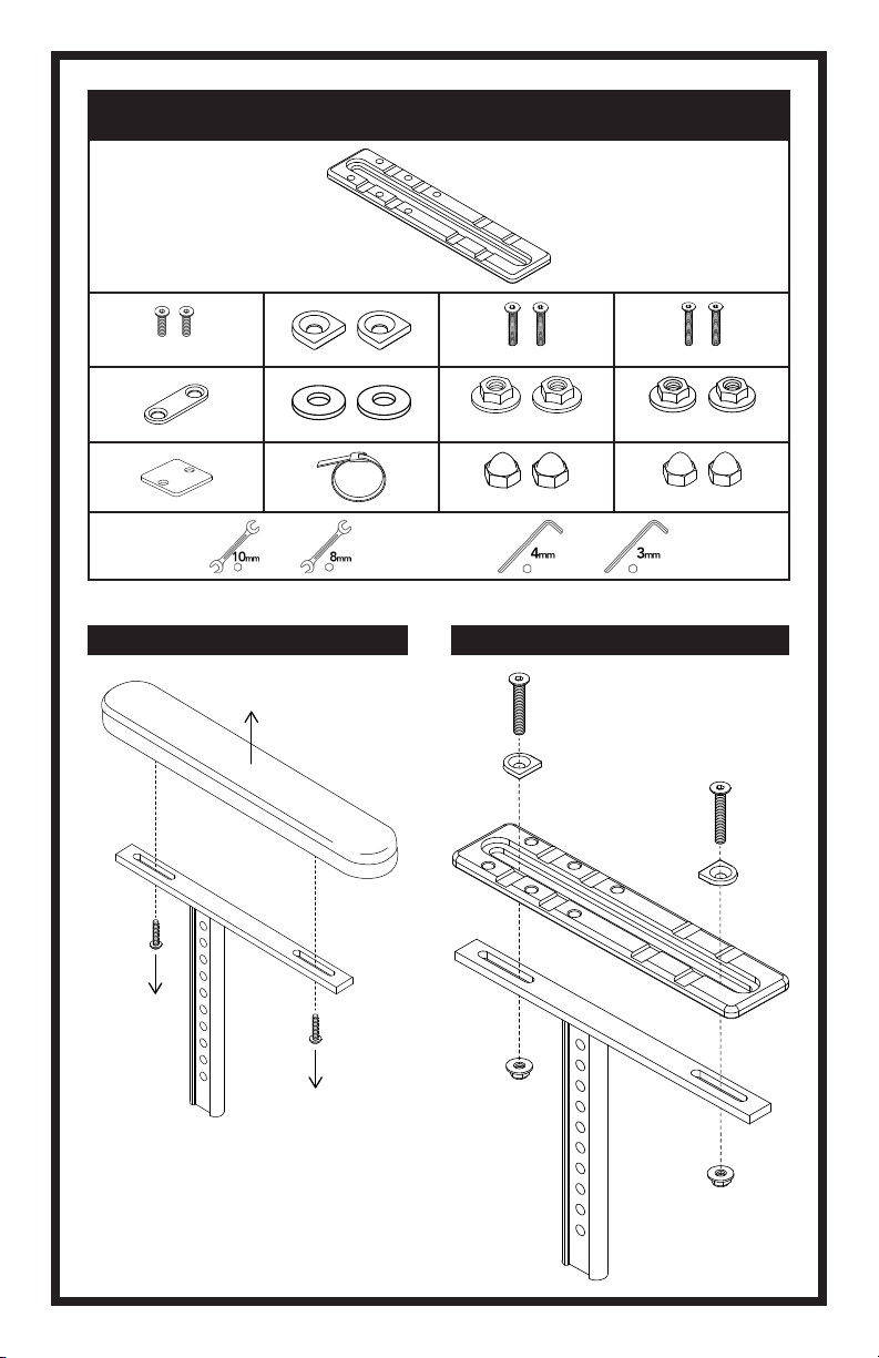
4mm Hex Key 3mm Hex Key
For Optional Fine-Tuning
the Quick-Release Latch
TOOLS REQUIRED
MOUNTING HARDWARE
OPTIONAL CLAMP OR PLATE SOLD SEPARATELY
ARMREST MOUNTING CLAMP SHOWN ABOVE
G H
Armrest
Mounting Clamps
Compatible with Ø19mm [3/4”] or Ø22/25mm
[7/8”/1”] Round Armrest Tubing
Armrest
Mounting Plate
Compatible with
Flat Armrests
B
C
D
G
E
F
A
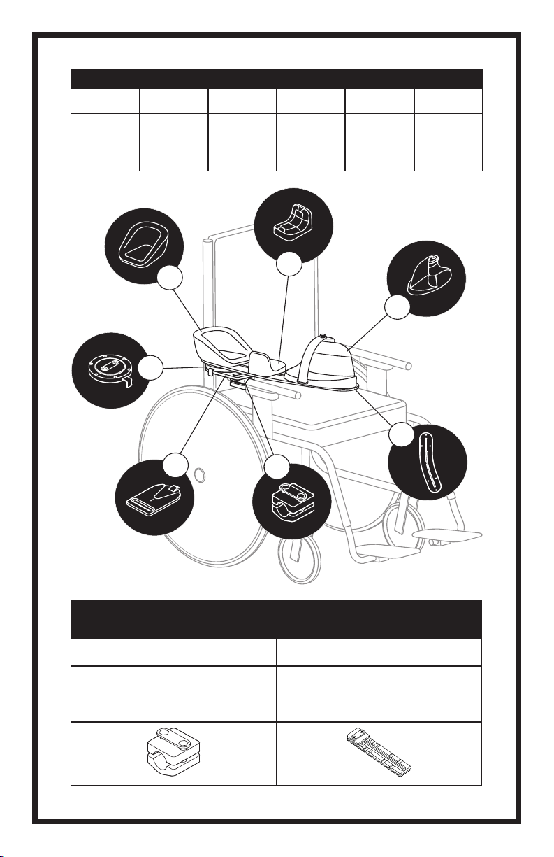
A B C D E F
Elbow
Pad
Forearm
Pad
Hand Block
and
Strap
Base
Board
Quick-
Release
Adapter
Plate
Pivot
Plate
PACKAGE CONTENTS
4. Angle
The Pivot Plate allows a 60° range of
internal to external rotation. To choose
the angle of the Arm Support, pull out
the Pivot Plate Tab and position the
Arm Support.
Push the Pivot Plate Tab in to lock at the
desired angle in 5° increments.
For more information see:
“ADDITIONAL FINE TUNING OF THE
PIVOT PLATE: ADDITIONAL INTERNAL
AND EXTERNAL ROTATION LIMITS.”
3. Lateral
To adjust the Arm Support closer or
further away from the user, loosen the
screws that attach the Quick-Release
Adapter Plate to the armrest mounting
hardware.
Slide the Arm Support inwards or
outwards and securely re-tighten both
screws.
3
4
1
2
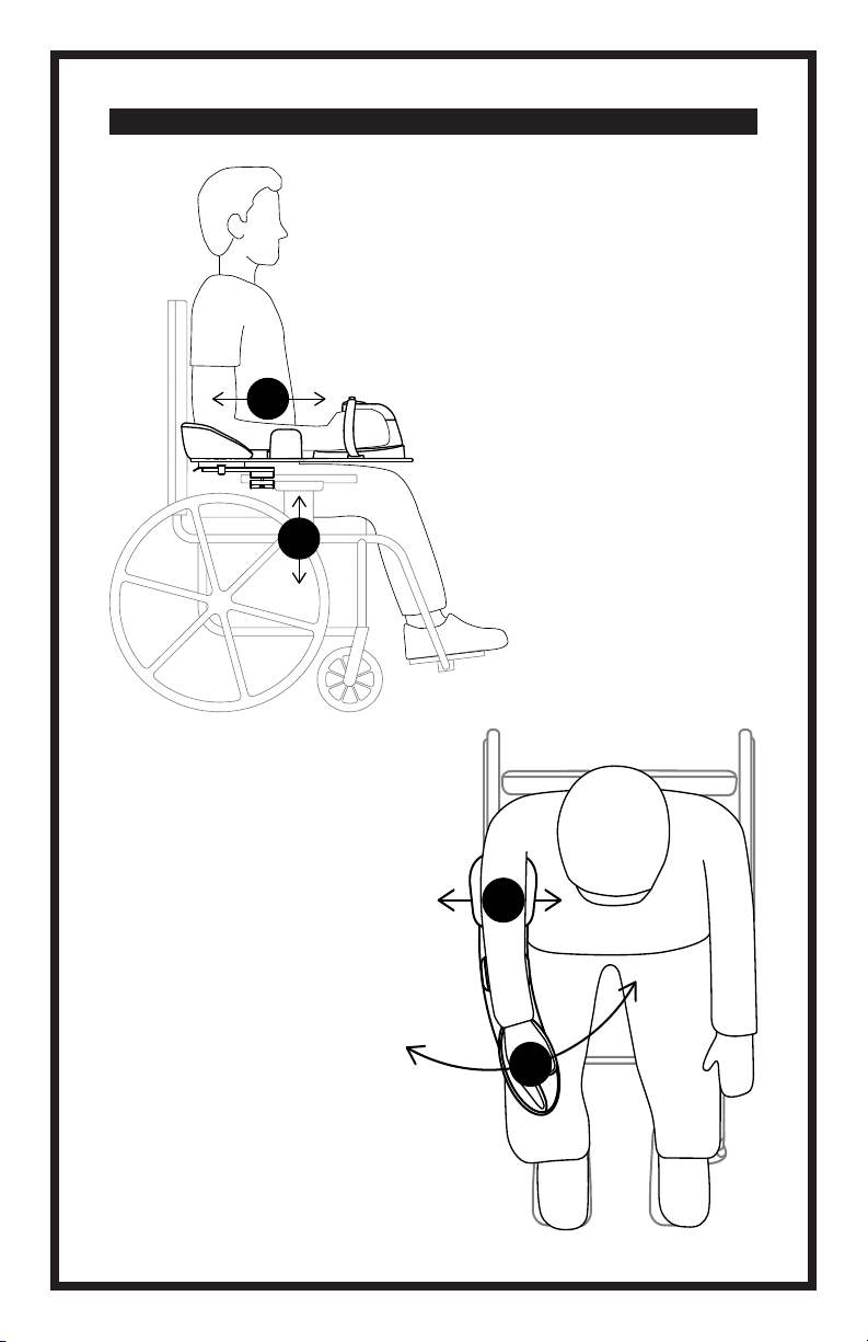
2. Depth
To adjust the Arm Support
forwards or backwards, loosen
the screws located on the armrest
mounting hardware.
Slide the Arm Support forwards
or backwards on the armrest into
the correct position.
For more information see:
“ADDITIONAL FINE TUNING OF THE
PIVOT PLATE: ADDITIONAL DEPTH
ADJUSTMENTS.”
1. Height
The use of a height-adjustable
armrest is recommended for
optimal positioning.
Adjust the height of the armrest
to support the elbow for even
pressure distribution of the arm
without lifting the shoulder.
POSITIONING THE ARM SUPPORT FOR THE USER

ADJUSTING THE FOREARM PAD AND HAND BLOCK
To adjust the Forearm Pad loosen the
M6 screws (2) and slide the Forearm
Pad along the Base Board to cradle the
user’s arm behind the wrist. It can be
adjusted in or out, rotated, or reinstalled
in the opposite direction to support or
limit arm movement. Re-tighten the
screws.
To adjust the Hand Block, loosen the
M6 screws (2) and slide the Hand
Block along the Base Board to prevent
shifting of the user’s forearm. Tighten
the rear screw until it is snug, then adjust
the angle of the Hand Block 0-30° to
properly position the hand and wrist.
Fully tighten both screws to secure the
Hand Block in place.
Begin by positioning the user’s elbow in the Elbow Pad.
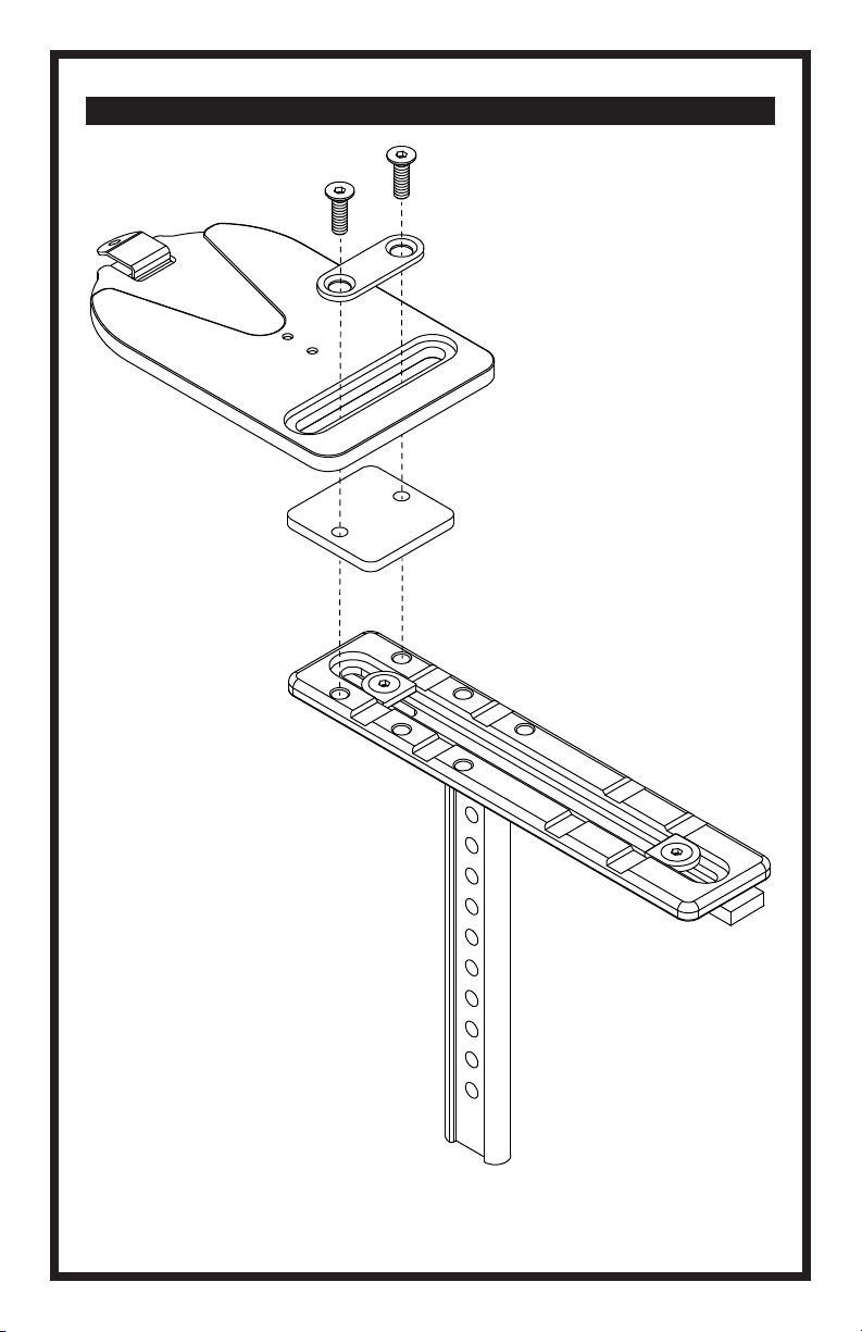
2. Mount the Hand Block
to the Base Board using
the Washer Plate and the
included M6 screws (2).
Note: Do not fully tighten
the screws until the nal
adjustments have been
made to t the user.
Note: The Quick-Release
Latch can be adjusted
to remove any play by
loosening the M5 screws
(2) on the bottom using
a 3mm hex key. Push the
Quick-Release Latch tightly
against the back edge of
the Quick-Release Wedge
while retightening the
screws to secure it in place.
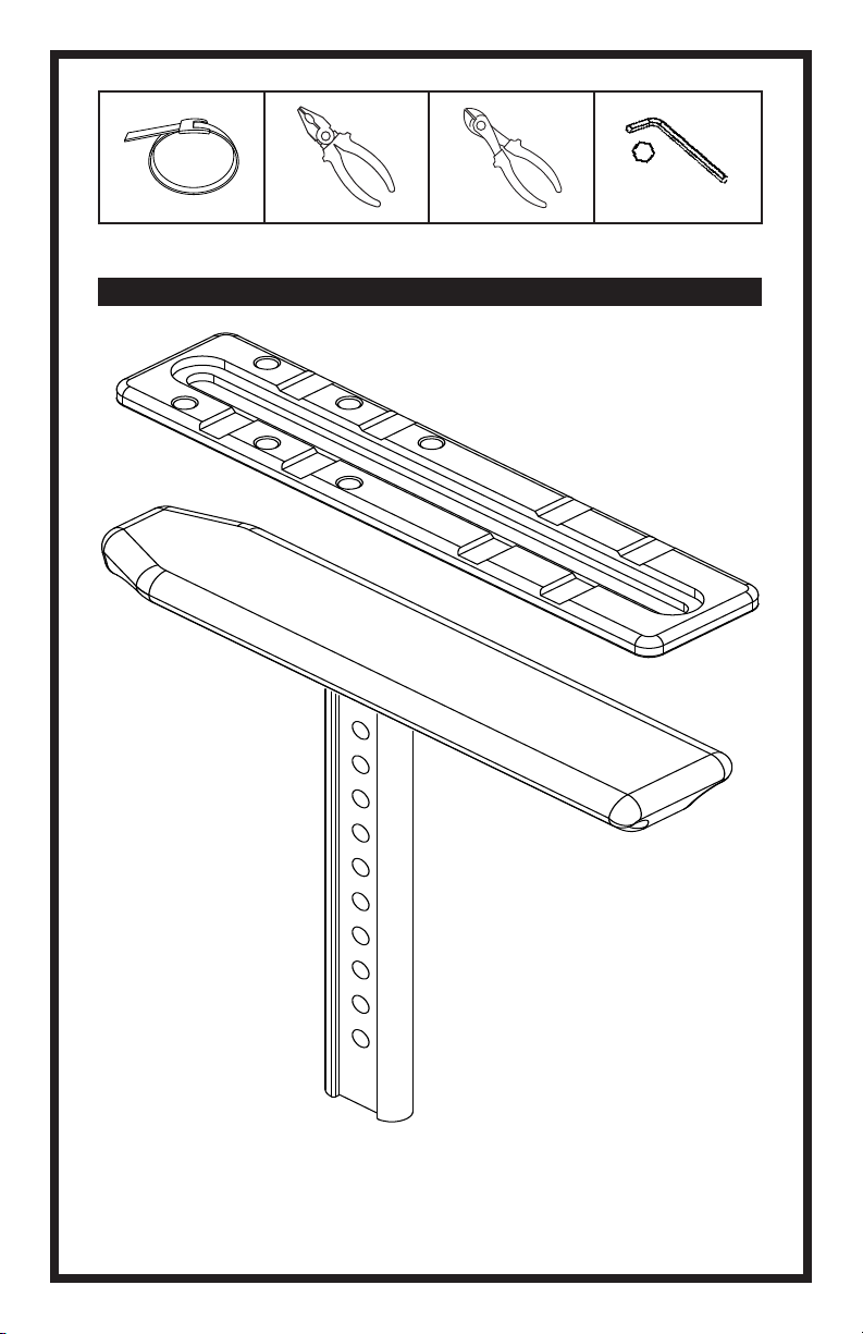
3. Slide the Arm Support into the Quick-Release Adapter Plate—the Quick-Release Latch should
lock with an audible “click!”
1. Mount the Quick-Release Receiver to the wheelchair armrest using optional armrest mounting
hardware. Partially tighten the mounting screws to allow for adjustment. See instructions included
with optional mounting hardware for details.
Prior to installation, remove the Quick-Release Receiver from the Arm Support. For more
information see: “USING THE QUICK-RELEASE ADAPTER PLATE.”
INSTALLING THE ARM SUPPORT

WARNING! Always monitor the user when the Pivot Plate is unlocked to rotate. The Pivot Plate
should always be locked when driving the wheelchair or transporting it in a vehicle to prevent
damage or injury that could result from striking doorways or other obstacles near the side of the
chair.
PIVOT
UNLOCK LOCK
The Arm Support can be unlocked to allow for dynamic movement or locked to maintain a xed
arm position.
To unlock, pull out the Pivot Plate Tab. The Arm Support can now rotate freely through a 60°
internal-to-external range.
To lock, push in Pivot Plate Tab. The Arm Support can be locked in 5° increments.
LOCKING/UNLOCKING THE PIVOT PLATE
Press down on the Quick-Release Latch to unlock for removal.
To reinstall, slide the Arm Support into the Quick-Release Receiver until it engages with an
audible “click!”
USING THE QUICK-RELEASE ADAPTER PLATE
User must be seated in wheelchair before performing safety check.
1. NORMAL OPERATION
2. COMFORT
3. POSITION
4. ADDITIONAL
Check for any pinch-points or loose parts.
Look for areas of irritation.
Conrm correct position of user’s upper
body and shoulders.
Move the chair through full range of motion,
including tilt, folding, and rolling, and check
for any interference and adjust the Arm
Support if necessary.
SAFETY AND PERFORMANCE CHECKS
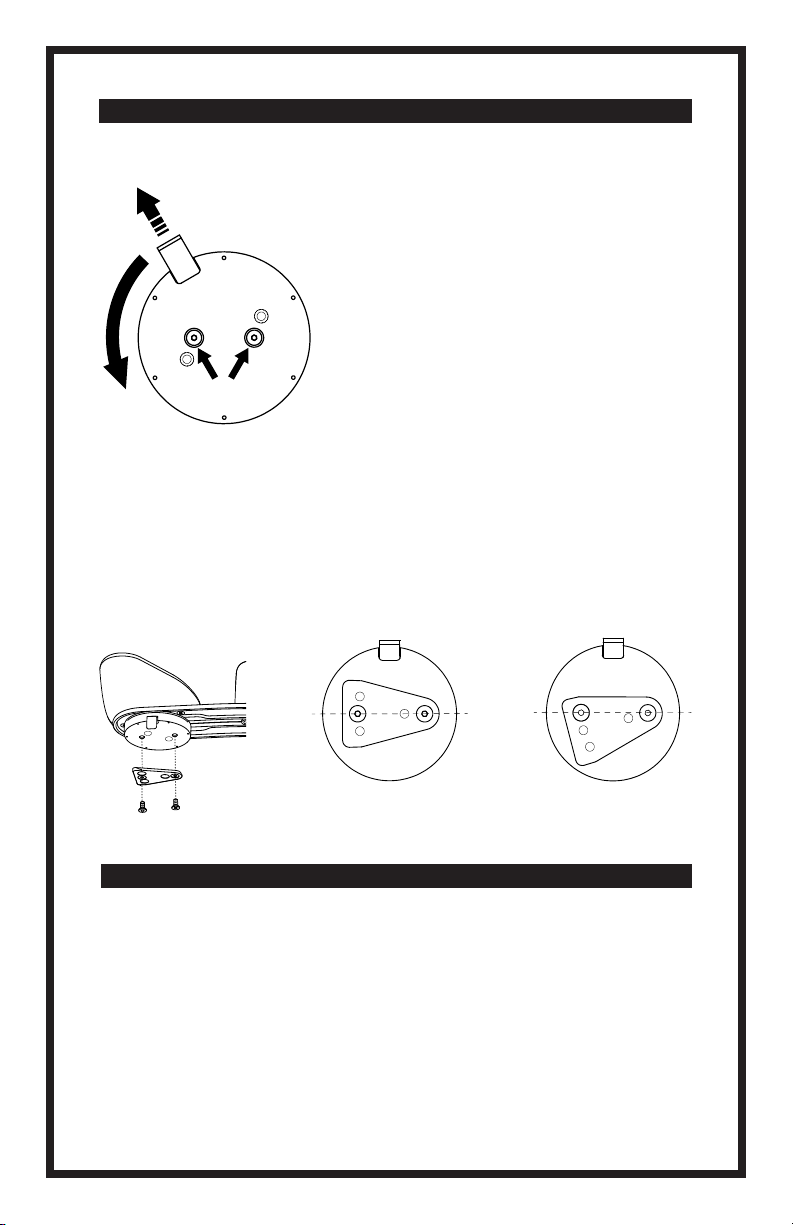
30°/30° 15°/45°
The standard setting of the Pivot Plate allows for 30° internal/30° external rotation from the neutral
position (aligned with the armrest of the chair). This provides the same function whether installed
on the right or left hand side.
Some users are capable of a greater range of internal arm rotation, which can be accommodated
by repositioning the Quick-Release Wedge on the bottom of the Pivot Plate to allow 45°
internal/15° external rotation.
ADDITIONAL INTERNAL AND EXTERNAL ROTATION LIMITS
Additional adjustments can be made by repositioning the
Pivot Plate up to 25mm forward on the Base Board.
To access the mounting screws, remove the Quick-Release
Wedge and pull out the Pivot Plate Tab to unlock and
rotate it until the M6 mounting screws are visible through
the two access holes.
Loosen both screws to slide the Pivot Plate forward,
then fully re-tighten both screws and reattach the Quick-
Release Wedge.
1
2
ADDITIONAL DEPTH ADJUSTMENTS
ADDITIONAL FINE TUNING OF THE PIVOT PLATE

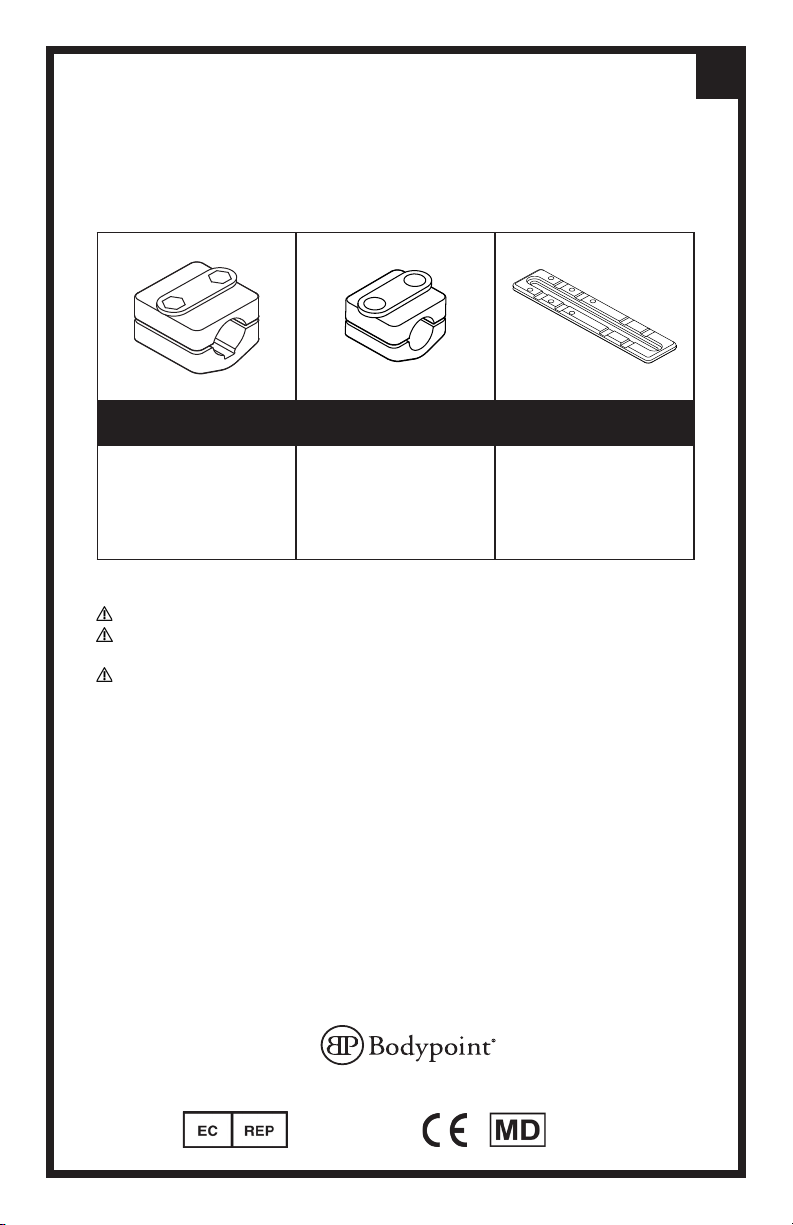
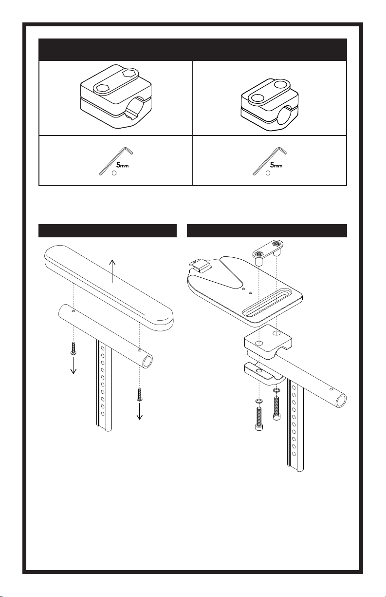
AS118 AS119 AS120
Armrest
Mounting Clamp
Compatible with Ø22/25mm
[7/8”/1”] Round Armrest Tubing
Armrest
Mounting Clamp
Compatible with Ø19mm [3/4”]
Round Armrest Tubing
Armrest
Mounting Plate
Compatible with
Flat Armrests
WARNING! This product should be installed and fitted by a qualified rehab technician.
WARNING! When mounting, check that the Arm Support is securely locked into the Quick-Release
Adapter Plate. The installer should hear an audible “click” sound.
WARNING! If a serious incident occurs related to the use of this product, it should be reported to the
manufacturer (Bodypoint, Inc.) and the local Competent Authority.
PERIODIC SAFETY AND PERFORMANCE CHECKS:
To ensure user safety, this product must be checked periodically for function and signs of wear. If
the product does not function correctly or if signicant wear is found in the parts, stop using it and
contact your supplier for qualied repair or replacement by Bodypoint®. Under no circumstance
should this product be altered or repaired by unqualied persons.
WARRANTY:
This product carries a limited lifetime warranty against defects in workmanship and materials arising
under normal use by the original consumer. Contact your supplier or Bodypoint® for warranty
claims. For more information on Bodypoint® products and information on distributors outside the
USA go to www.bodypoint.com.
ART NOS.: AS118, AS119, AS120
Mounting Hardware Instructions
en
BPI117-en2023.5© 2022 Bodypoint, Inc. All rights reserved.
558 1st Ave. S., #300, Seattle, WA 98104, USA l 206.405.4555 l 800.547.5715 l www.bodypoint.com
Medical
Device
Bodypoint Europe BV
Kerkstraat 29
7396 PG Terwolde
The Netherlands
Moduform Dynamic Arm Support
AS118 AS119
1 2
AS120
M6x20mm
M6x35mm
M5x35mm
M6
M5
X4
M6
M5
21

3
4
1
5mm

2

3
BPI118-da2023.5
© 2022 Bodypoint, Inc. All rights reserved.
558 1st Ave. S., #300, Seattle, WA 98104, USA l 206.405.4555 l 800.547.5715 l www.bodypoint.com
Medical
Device
Bodypoint Europe BV
Kerkstraat 29
7396 PG Terwolde
The Netherlands
AS115L AS115R
AS116L AS116R
AS200R
ART NOS.: AS001
Moduform dynamisk armstøtte
VEJLEDNINGE: PAKKENS INDHOLD
da

M6x20mm
M5x35mm
M6x35mm
M5
M6
M5
M6 X4
AS120
AS118
Ø22/25mm [7/8”/1”]
AS119
Ø19mm [3/4”]
This manual suits for next models
12
Table of contents
Languages:
Other Bodypoint Medical Equipment manuals

Bodypoint
Bodypoint EVOFLEX EB205 Guide

Bodypoint
Bodypoint Ankle Huggers FT210 Guide

Bodypoint
Bodypoint Stayflex SH350 Guide

Bodypoint
Bodypoint BB111 Guide

Bodypoint
Bodypoint Ankle Huggers FT240 Guide

Bodypoint
Bodypoint SP110S Guide

Bodypoint
Bodypoint Anterior Trunk Support User manual

Bodypoint
Bodypoint PivotFit SH290 Guide

Bodypoint
Bodypoint BB101M-1 Guide

Bodypoint
Bodypoint HW100-150 Guide


