Henry Schein COLPOSCOPE I User manual

HENRY SCHEIN COLPOSCOPE I
USER’S MANUAL
(570-0144 and 570-0145)
Distributed by (in US only)
HENRY SCHEIN INC.
135 DURYEA ROAD MELVILLE, NY 11747 USA
MC-55-248-001 REV 4/2016
yyyy-mm-dd

2
570-0144 and 570-0145
Focusing Mount and Zoom Body
Please read this manual carefully before operating your Colposcope.
We thank you for choosing the Henry Schein® Articulating Arm Colposcope. This precisely
built, durable Colposcope will give you years of service. If ever you require an additional
accessory or spare part, please contact your Henry Schein® Representative.
General Information:
The Colposcope described in this manual is designed to be used by properly trained
personnel in a suitably equipped practice/exam facility. For the correct and safe use of this
Colposcope it is essential that personnel follow generally accepted safe procedures in
addition to the safety precautions called for in this manual.
The internal components of the illumination base can be hazardous due to high voltage and
its cover should not be removed. ANY Servicing must be done by an authorized person.
Please carefully read the Safety, Electrical and Warning instructions below.

3
Safety
This Colposcope has been designed and tested in accordance with EN 61010 Safety
Requirements for Electrical Equipment for Measurement, Control, and Laboratory Use.
This Colposcope has been supplied in a safe condition. Read the following before installing
and using the instrument and its accessories.
Electrical
Before switching on the Colposcope, make sure it is set to the voltage of the local power
supply, 110 V in the U.S.A. Using the wrong voltage can damage the instrument.
The main plug shall be inserted into a grounded outlet.
Warning
Any interruption of the protective conductor inside or outside the Colposcope or
disconnection of the protective earth terminal has the potential to make the Colposcope
dangerous. Intentional interruption is prohibited. Whenever it is likely that the protection
has been impaired, the Colposcope shall be made inoperative and be secured against any
unintended operation.
Environment
The instrument is designed and engineered for indoor use only. The optimum environment
for the Colposcope is:
Temperature 5 –35 C (41-95 °F)
Humidity 85 %
Service
Repairs may only be carried out by trained service technicians, or by authorized personnel.
Contact Henry Schein® for details.
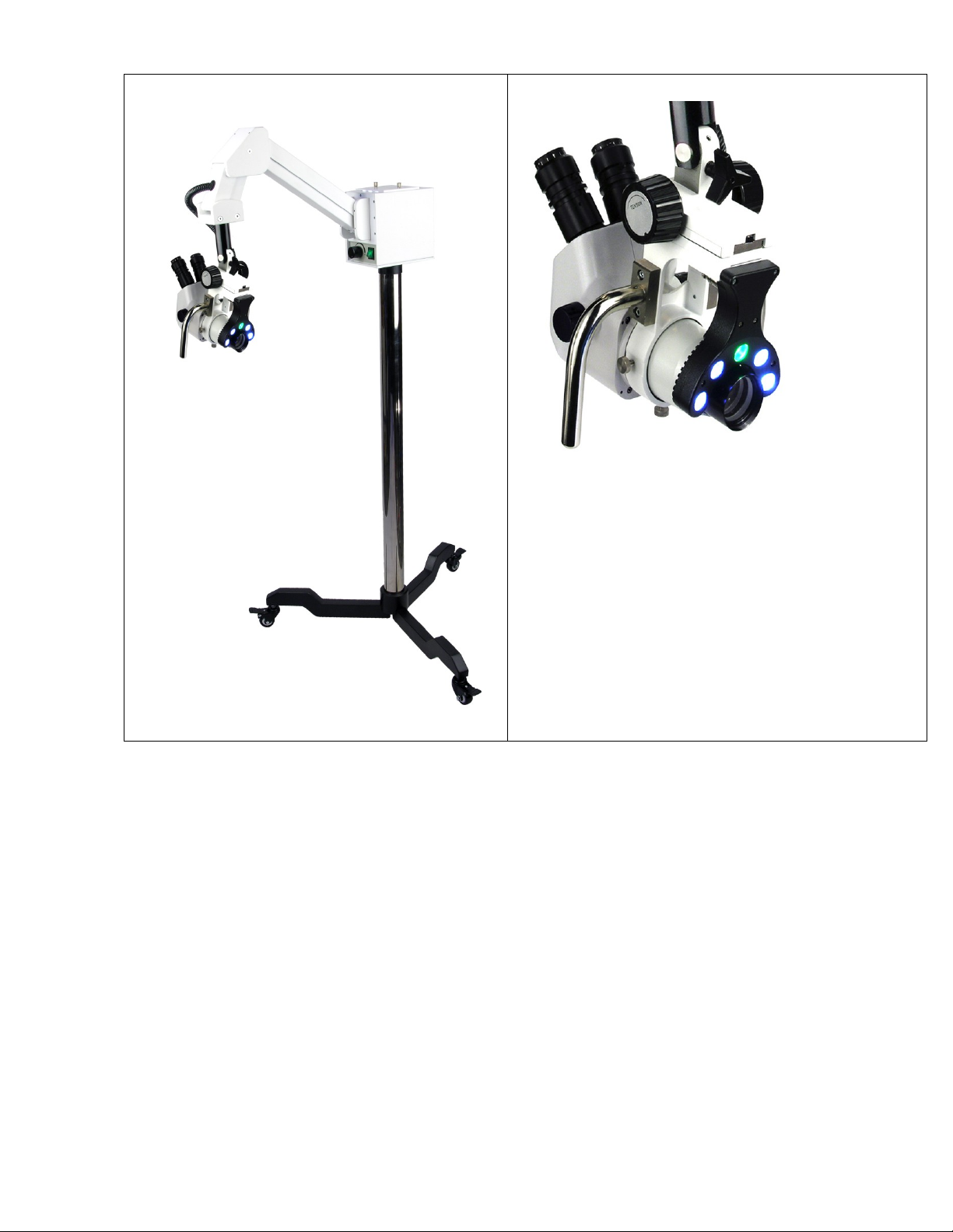
The Henry Schein® Articulating Arm Colposcope is an optical instrument for use as a
diagnostic aide. The system includes three main components:
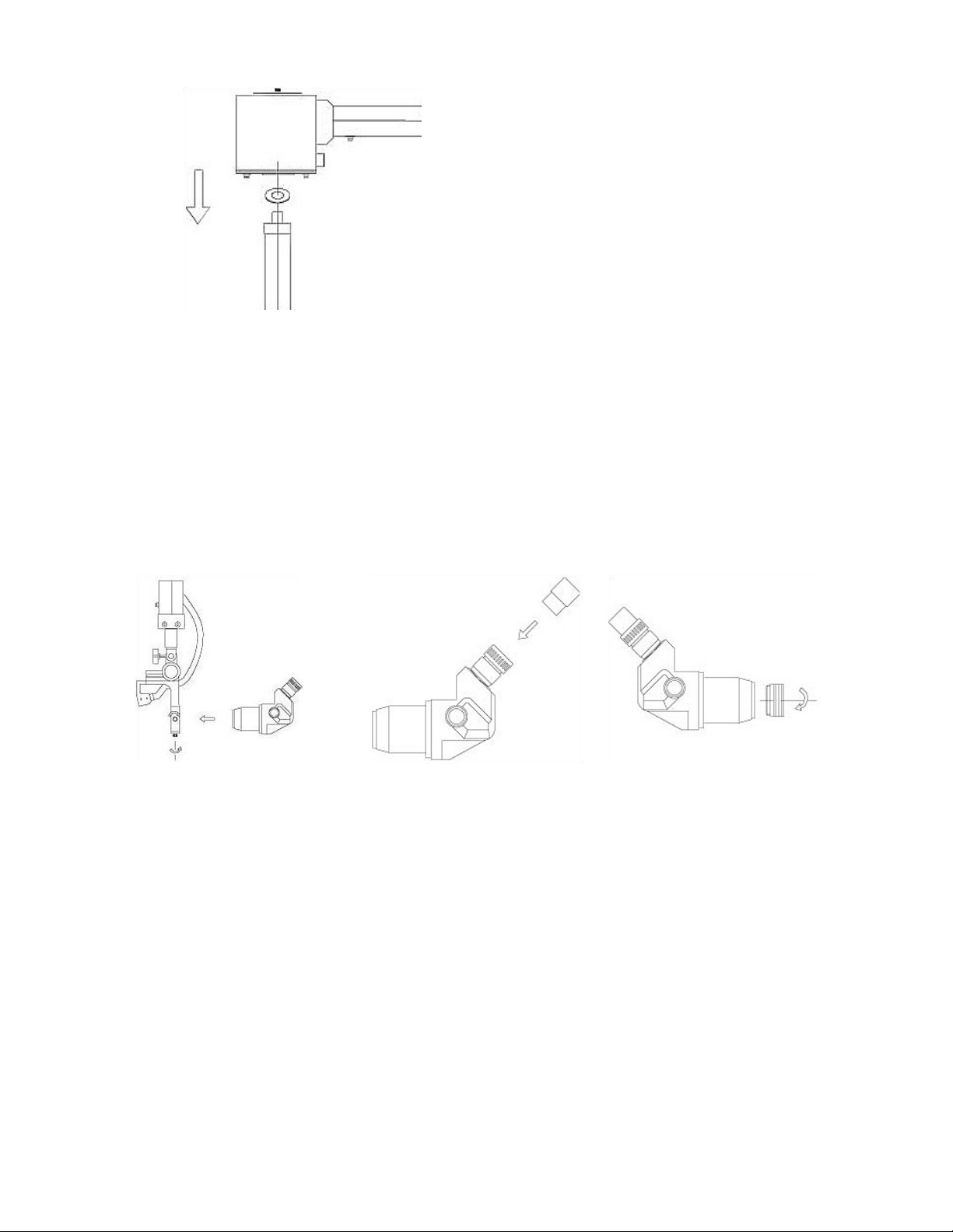
1. Stereo microscope head with zoom magnification optics
2. LED light source
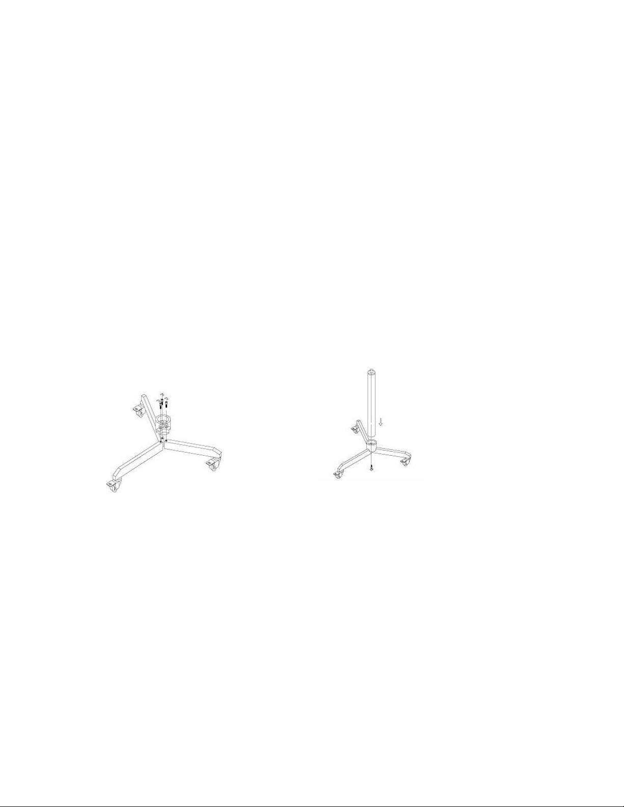
3. Mobile articulating-arm stand and base.
Features and specifications of the Colposcope
-Boom arm suspension mounted on three-legged mobile floor stand with locking casters.
-Suspension joints maintain boom arm position.
-4 White and 1 Green LED light with dual intensity control.
-Ratio of zoom head magnification is 1:6.7 (0.67X-4.5X).
-Eyepieces: Standard WF20X/11.5mm.
-Objective Lens 0.3X (standard).
-Working distance: 298mm.
-Magnification: 3.9X-27X (with 0.3X objective and WF20X eyepiece).
-Inclination of binocular tube: 45°-90°adjustable.
-Adjustment of interpupillary: 55mm-75mm.
-Dimensions:

4
Overall height: 63″ (1600mm)
Overall weight: 77.1bs/35kgs (stand 69.1bs/31.5kgs, head 8.1bs/3.5kgs)
Center of column to the end of leg: 16-1/2″ (420mm)
The horizontal distance from the center of column to the mount of the zoom body is
30″ (780mm)
Height 63″ (1600mm)
Assembly of the Articulating-Arm Stand and Base
Base and Column Installation
1. Insert the leg inside the center base attachment.
2. Line up the hole underneath the base attachment with the hole of the leg and insert the
bolt (Fig.2). Only one 3/16” Allen wrench is needed (Allen wrenches are supplied with
your Colposcope). To tighten, you will need to use the stainless steel torque tube,
included with the 3/16” Allen wrench. Use the torque tube to increase leverage on the
Allen wrench to tighten the bolts.
3. Repeat for all 3 legs.
4. Engage the brakes to prevent the base from rolling.
5. Place the pole column in the column mount hole of the base attachment. Carefully tilt the
base on its side and insert the bolt. Tighten it using the Allen wrench provided (Fig. 3).
Fig. 2
Fig. 3
Suspension Arm Installation
1. Be sure the white Teflon Ring is placed over the pin on the top of the column before
mounting (Fig. 4).
2. Place the illumination box and suspension arm assembly on to the top of the column. The
hole in the bottom of the illumination box will fit over the column post.

5
Zoom Head Installation
1. Insert the Colposcope head into the focusing mount (Fig. 5).
2. Tighten the locking screws (Fig. 5).
3. Insert the eyepieces into the eyepiece tubes of the binocular or trinocular head (Fig. 6).
4. Screw the objective lens clockwise onto the bottom of the Colposcope head (Fig. 7).
Fig. 5
Fig. 6
Fig. 7
Arm Tension Adjustment
The Colposcope arm tension is adjusted and tested prior to leaving the factory. The arm may
be moved into any position and will hold its position. The suspension system is factory set to
assure the stability of the instrument. Arm adjustment should not be needed. If necessary,
further adjustment may be done following the procedures below.
To tighten up / down motion of the arm
1. Find the set screws labeled “A”on the picture in (Fig. 8). With an Allen wrench, turn the
screw clockwise in small steps to set the arm movement to desired tension.
2. All set screws should be tightened in the same manner.
Fig. 4

6
Fig. 8
To tighten left / right motion
Find the set screws labeled “B”(Fig. 9) and follow the same instructions as above in
tightening up and down motion.
Fig. 9

7
Magnification and Power (magnification) Setting
Zoom Setting
Eyepiece: WF20X
Objective lens: 0.3X
Working distance: 298mm
Mag. power
Field of view
0.67X
3.9X
58.5
1X
6X
38.3
1.5X
9X
25.6
2X
12X
19.2
2.5X
15X
15.3
3X
18X
12.8
3.5X
21X
11
4X
24X
9.2
4.5X
27X
8.5
Total magnification = eyepiece × head power on power knob × objective lens (Fig. 10)
Fig. 10
With 20X eyepiece and 0.3X objective lens:
At the lowest setting of the magnification power knob (0.67), the total magnification is 20×0.67×0.27=3.9X
At the highest setting of the magnification power knob (4.5), the total magnification is 20×4.5×0.3= 27X
Fuse Replacement
Caution: Always unplug the Colposcope before replacing the fuse.
The fuse is located in the fuse holder which is part of power inlet socket. Use a small screw
driver to pull the fuse holder slot out, replace the fuse and push it back in.
The fuse is 2AMP, 250V fast blow fuse (P/N CS-9002). Replace only with specified type and
rating.
Positioning the Colposcope
-Set the Colposcope in front of the examination table so that one leg is perpendicular to
the table and in line with the Colposcope suspension arm (Fig. 11A, 11B).

8
-Each leg is equipped with a locking caster/wheel. If desired, they may be individually
locked by pushing down on the lock lever; to unlock, lift up the lever. (Fig. 11A, 11B)
Fig.
11A
Fig. 11B
Operation
-Turn the On/Off switch to “ON”; adjust the light intensity by turning the adjustment
knob.
-Make sure that the eyepieces are installed and that the head is secured by the
thumbscrews in the focusing mount.
1. Set the intended viewing spot of the examination to the center of view field using the
handles (Fig.12).
Fig. 12 (Articulating arm shown)

9
2. Use the handles and focusing knob to focus on the surface of the cervix (Fig. 13).
Fig. 13
3. The tension of the focusing knobs has been pre-set by factory technicians.
To increase the focusing tension, hold the left knob with your left hand; use your right
hand to turn the right knob clockwise. To check the tension, release your left hand and
rotate the knob with either or both hands in the same direction. If it is not tight enough,
repeat the above step until the proper tension is set.
To decrease the focusing tension, hold the left knob with your left hand; use your right
hand to turn the right knob COUNTERCLOCKWISE. To check the tension, release your left
hand and rotate the knob with either or both hands in the same direction. If it is not
loose enough, repeat the above step until the proper tension is set.
Zoom Head Adjustments and Setting Procedures
Interpupillary Distance Adjustment (Fig. 14) –change the distance between eye-tubes until
you get a single non-overlapping image (range is 55mm to 75mm).
Fig. 14

10
Focusing
Rotate the zoom knobs to the highest power 4.5x (Fig. 15). Set the diopters on both eyepiece
tubes to “0” (Fig.16). Then use the focusing knobs to focus on the cervix.
Fig. 15
Fig. 16
Rotate the zoom knobs to get the lowest power 0.67x (Fig. 17). DO NOT TOUCH the focusing
knob on the focusing mount.
Fig. 17
Look through the right eyepiece; rotate the eyetube (Fig. 18) until the image is precisely in
focus (the diopter is now properly set). Do the same for the left eyepiece to set the diopter.
Fig. 18
Bring the zoom to the highest power (4.5X) again. If the image is not in sharp focus, use the
focusing knob on the focusing mount to bring the specimen in focus. The image should
remain sharp throughout the entire zoom range.
This manual suits for next models
2
Table of contents
Other Henry Schein Medical Equipment manuals

Henry Schein
Henry Schein COLPOSCOPE II User manual

Henry Schein
Henry Schein HS-Vet User manual

Henry Schein
Henry Schein OneStepPlus User manual

Henry Schein
Henry Schein Maxima 900-3510 User manual

Henry Schein
Henry Schein Urispec Plus User manual

Henry Schein
Henry Schein 900-6368 User manual

Henry Schein
Henry Schein 900-8275 User manual

Henry Schein
Henry Schein MD300K2 User manual

Henry Schein
Henry Schein Hydrim C61WD User manual