Mikasa MCD-L14H User manual

MCD-L14H
602-01507
*602-01507*
http://www.mikasas.com
en
CONCRETECUTTER
INSTRUCTIONMANUAL
Contentsof“DeclarationofConformity”
PleaserefertheECDECLARATIONOFCONFORMITY
inthismanualaswell.
CODE

PRGHO MCD-1UBLH MCD-L14H MCD-218CEH
(TXLSPHQW
LWHPQXPEHU 654118 654179, 654180,
654181
654280, 654290,
654297, 654298,
654299
6HULDOQXPEHU
SRZHUVRXUFH
FRQWRXWSXW
PD[RXW
S
XW!
Honda GX-200
3.7kW <4.1kW>
Honda GX-200
3.7kW <4.1kW>
Honda GX390UT
6.6kW <8.2kW>
0HDVXUHG
VRXQGSRZHU
OHYHOG%
107 107 115
*XDUDQWHHG
VRXQGSRZHU
OHYHOG%
108 108 116
2SHUDWRUV
VRXQGSUHVVXUH
OHYHOG%
87 88 93
+DQG$UP9LEUDWLRQ/HYHO
02'(/ $KYPVHF
MCD-1UBLH
㻤㻚㻞
MCD-L14H
㻡㻚㻟
MCD-218CEH
㻤㻚㻟
5HPDUNV
Vibration Level is in comply with EU Directive2002/44/EC and the value is
shown as 3 axix min. vibration level.
Test course ( Crushed gravel ) is in comply with EN500-4.
The above values are subject to change in case that the machine is modified
or/and the required regulations change.
Director, R&D Division
Mikasa Sangyo Co., Ltd.
18) Place and date of the declaration
Keiichi YOSHIDA
Tokyo, Japan June, 2016
Signed by:
17) EC Conformity Certificate No: SNCH*2000/14*2005/88*0472*04
For serial number, please refer it on front page.
14) Related Directive
Directive(& and, to be followed by Directive (&,
relating to the noise emission in the environment by equipment for
use outdoors.
12) Conformity assessment according to Annex: VIII (Full Quality Assurance procedure)
13) Name and address of the Notified Body
Société Nationale de Certification et d’Homologation (SNCH)
11, route de Luxembourg
L-5230 Sandweiler 䚷LUXEMBOURG
16) Other related Community Directives (&(&(&(&(&
EN500-1, EN500-4
15) Declaration The equipment referred in this document, fulfills with all the
requirements of Directive 2000/14/EC
'(&/$5$7,212)&21)250,7<
7\SH9LEUDWRU\5DPPHUV
2) Manufacturer’s name and address.
3) Name and address of the person who keeps the
technical documentation.
Mikasa Sangyo Co., Ltd.
4-3, Sarugaku-cho 1 chome, Chiyoda-ku, Tokyo101-0064, Japan
Takahiro Kishino, engineer
R&D Division, Mikasa Sangyo Co., Ltd.
Shiraoka-city, Saitama, Japan

Italian
1. DICHIARAZIONE “CE” DI CONFORMITÁ
2. Nome e indirizzo Fabbricante
3. Nome e indirizzo della persona che conserva la
documentazione tecnica
4. Tipo: Piastre vibranti
5. Modello
6. Codice macchina
7. Numeridi matricola
8. Potenza installata netta <resa massima>
9. Livello di potenza sonora misurato (dB)
10. Livello di potenza sonora garantito
11. Livello massimo di pressione sonora
12. Valutazione di conformità in accordo all'annesso VIII
( procedura Garanzia di Qualità totale
13. Nome dell'organismo notificato
14. Rappresentante Autorizzato in Europa
15. Direttiva di riferimento
Direttiva 2000/14/CE su l'emissione acustica ambientale
delle macchine ed attrezzature destinate a funzionare
all'aperto
16. Dichiarazione
Le attrezzature riportate nel documento soddisfano i requisiti
della Direttiva 2000/14/CE
17. Altre Direttive Comunitarie di riferimento
18. Certificato di Conformità CE No:
19. Luogo e data della dichiarazione
French
1. DECLARATION « CE » DE CONFORMITE
2. Non et adresse du Fabricant
3. Nom et adresse de la personne qui défient les documents
techniques
4. Type du materiel: Plaques vibrantes
5. Modello
6. Numero equipement
7. Numéro de série
8. Puissance reseau <rendement maximal>
9. Niveau sonore mesure(dB)
10. Niveau sonore garanti(dB)
11. Niveau sonore maximum
12. Certification de conformite selon l'annexe VIII ( procedura
Garanzia di Qualità totale )
13. Nom et adresse de l'organisme notifié
14. Mandataire dans la Communaute Europeenne
15. Directive concernee
Est egalement conforme aux dispositions de la directive
<<emission sonores des equipements utilises a l'exterieur
des batiments>> 2000/14/CE et aux legislations nationales
la transposant.
16. Declaration
L'équipement de référence satisfait aux exigences de la
Directive 2000/14/EC
17. Autres directives communautaires concernees
18. Certificate deConformite CE numero:
19. Lieu et date de la declaratio
Spanish
1. DECLARACIÓN “CE” DE CONFORMIDAD
2. Nombre y dirección del fabricante
3. Nombre y dirección de la persona que guarda la
documentación técnica.
4. Tipo: Bandejas vibrantes
5. Modelo
6. Número de referencia del equipo
7. Numeros de serie
8. Potencia neta instlada <rendimineto maximo>
9. Nivel sonoro medido del motor ( dB )
10. Nivel sonoro garantizado del motor ( dB )
11. Máximo nivel sonoro de presión ( dB )
12. Evaluación de la Conformidad de acuerdo al Anexo VIII
( Prcedimiento de total garantía asegurada )
13. Nombre y dirección de la Entidad Notificada
14. Representante autorizado
15. Directiva relacionada
Directiva 2000/14/CE en relación a la emisión sonora en el
ambiente por equipos que trabajan en espacios abiertos
16. Declaración
El equipo referido en este documento , cumple con todos los
requerimientos de la Directiva 2000/14/EC
17. Otras Directivas Comunitarias relacionadas
18. Certificado de Conformidad CE Nº
19. Lugar y fecha de la declaración

1
1
2
2
2
3
3
3
4
4
5
5
5
6
7
7
8
9
9
9
10
13
13
14
14
15
15
15
16
17
18
18
19
General Cautions
Refueling Precautions
Location And Ventilation Precautions
Precautions Before Starting
Precautions During Work
Lifting Precautions
Precautions In Transportation / Safekeeping
Precautions In Maintenance
Installed Place Of Every Decal
Warning Labels And Information
Dimensions
Parts And Compornent
Main Body
Engine
Starting Up
Working
Loading And Unloading
Precautions In Transportation
Gasoline Engine
Machine
1.
2.
3.
4.
5.
6.
7.
8.
9.
10.
11.
12.
13.
6.1
6.2
8.1
8.2
10.1
10.2
13.1
13.2
4.1
4.2
4.3
4.4
4.5
4.6
4.7
4.8
4.9
4.10
5.1
5.2
INTRODUCTION ......................................................................................
MACHINERY OVERVIEW ........................................................................
WARNING SIGNS ....................................................................................
CAUTIONS FOR SAFETY........................................................................
APPEARANCE.........................................................................................
SPECIFICATION......................................................................................
BEFORE STARTING YOUR OPERATION...............................................
OPERATION ............................................................................................
STOPPING...............................................................................................
TRANSPORTAION...................................................................................
STORAGE.................................................................................................
PERIODIC CHECK AND COORDINATION..............................................
TROUBLESHOOTING .............................................................................
TABLE OF CONTENTS

1
1䠊INTRODUCTION
2䠊MACHINERY OVERVIEW
Mikasa Concrete Cutter is used to cut the concrete or asphalt road surface by Diamond Blade that is attached on its Blade
shaft.Pleasechoosemachinetypebycuttingdepth,andthenchooseappropriateblade to match the spot situation, such as
material age, presence or absence of reinforcement in the concrete.
Please use this machine to cut plain concrete, reinforced concrete and asphalt only.
Do not cut sediment, for that it flies into pieces and injuries man around the machine.
This cutter can be equipped with diamond blade only. Do not attach resinoid blade on this machine. Please pour water to
blade at cutting except using dry-type blade, for that conglutination of the blade or Blade chip flies into pieces.
Do not use this machine in the state that you turned more than the number of turn in accord with the blade, for that congluti-
nation of the blade or Blade chip flies into pieces.
Donot use this machine ininstability,or in a roughground,for that conglutination of thebladeor Blade chip flies intopieces.
Do not use this machine to cut a secondary product concrete.
EngineofConcreteCutterisfixedonamainbodybase, andconveyspower toBladeshaft withtheVbelt.Thewayofadjust-
ment of V-belt tension is making Engine slide.
Belt cover, Handle guide, Handle for elevating the blade, and Blade cover which can be put on and off easily is attached on
Engine Base. Cutting depth is adjusted by rotating Handle for elevating the blade through BladeArm that is equipped with
Front wheel The way to travel the machine is pushing the machine directly.
Air-cooled petrol engine is amounted on Mikasa Concrete Cutter as power source.
V-pulleyisattachedonEngineshaftfordrivingBladeshaft,andDiamondBladeisattachedonBladeshaft.Thecuttingdepth
can be adjusted to change the Front wheel position by Handle.
The way of driving the machine while cutting is pushing the handle.
TThis instruction manual describes the proper methods for using Mikasa CONCRETE CUTTER, as well as simple
checks and maintenances. Be sure to read this instruction manual before operation, in order to get full use of the excel-
lent performance of this machine, as well as to improve your operation and to perform engineering work effectively.
After reading this manual, store it in a handy location for easy reference.
For details about the engine of this machine, see the separate instruction manual.
Forinquiriesaboutrepairparts,parts lists, service manuals, and repairs, please contact the store where youpurchased
the product, our sales office, or the Mikasa Parts Service Center. For parts lists, please visit our homepage at:
http://www.mikasas.com/ where you can access Mikasa WEB parts lists.
䖃
䖃
䖃
䖃
Application
Warning About Incorrect Applications And Techniques
Structure
Power Transmission
The illustrations in this manual might slightly differ in part from the machine you actually
purchased due to design changes.

2
3䠊WARNING SIGNS
4䠊CAUTIONS FOR SAFETY
The triangle shaped marks used in this manual and on the decals stuck on the main body
indicate common hazards. Be sure to read and observe the cautions described.
Do not work with this machine, when
Read this instruction manual carefully and handle the machine as described so that you
can work safely.
For details about the engine, refer the separate instruction manual for the engine.
Make sure you thoroughly understand the construction and operation of the machine.
Please check each part before work, and execute the scheduled check and alignment
regularly.
To work safely, always wear protective clothing (helmet, safety glasses, safety shoes,
ear plugs etc.) and appropriate work clothes.
Please wear Hearing protector ( noise protective equipment of ear muff or ear stoppers)
by all means.
Always check the machine to make sure that it is normal before starting operation.
The decals on the machine body (operating methods, warning decals, etc.) are very im-
portant to ensure safety. Keep the machine body clean so that they can be read at all
times. If any decal cannot be read, replace it with a new one.
It is very dangerous if children come into contact with the machine. Take the utmost
care how and where the machine is stored.
Before performing any maintenance, be sure to turn the engine off.
Mikasa does not accept any liability for accidents or problems caused as a result of not
using genuine Mikasa parts or if the machine has been modified.
you are tired or sick and not feeling well,
you have taken medicine or drug, or
you have had a drink.
4.1 General Cautions
䖃
䖃
䖃
䖃
䖃
䖃
䖃
䖃
䖃
䖃
䖃
䖃
䕿
䕿
䕿
Warning labels indicating hazards to humans and to equipment.
DANGER
䟿
WARNING
䟿
CAUTION
䟿
CAUTION
䟿
Denotes an extreme hazard. It calls attention to a procedure, practice,
condition or the like, which, if not correctly performed or adhered to, is
likely to result in serious injury or death.
Denotes a hazard. It calls attention to a procedure, practice, condition
or the like, which, if not correctly performed or adhered to, could
result in serious injury or death.
Denotes a hazard. It calls attention to a procedure, practice, condition
or the like, which, if not correctly performed or adhered to, could
result in injury to people and may damage or destroy the product.
Failure to follow the instructions may result in damage to property.
䟿
(without at )
WARNING
䟿
CAUTION
䟿

3
Always refuel in a well ventilated area.
Make sure to stop the engine and wait until the engine cools down when refueling.
Select a flat surface area with no flammable material around for refueling. Be careful
not to spill the fuel. Wipe off well if there is any spill.
Never put fire near the machine during refueling. (Especially, be careful about
smoking.)
If you fill to the top of the fuel tank inlet, fuel might spill out from the tank, and it
becomes dangerous
After refueling, tighten the tank cap well.
Do not run the machine in an unventilated location, such as indoors or inside a tunnel.
The exhaust gas from the engine contains toxic gases such as carbon monoxide and
is very hazardous.
Do not operate the machine near open flames.
Check the clamping condition of each part. Cause the big failure that does not think
that a screw loosens by vibration. Tighten the screw well.
Confirm that the diamond blade does not have anomaly such as deficit of the blade
chip or the crack of the board.
If the machine were not run more than 3 months, be sure to start at low speed in a
few minutes to warm up thoroughly,
for the reason to avoid engine seizure by oil film shortage.
When starting and working with the machine, confirm that neighboring people and
obstruction are safe.
Always pay attention to foothold and work in easy position that allow to keep your
machine in good balance.
Be careful not to touch muffler and engine body as it becomes hot in operation or just
after operation.
Discontinue operation promptly whenever your machine goes deficient or you notice
any abnormality.
Be sure not to make the cutter with blade stand-by for work.
In the case to be without avoidance, be sure to run the engine at low speed possibly
in a short time.
(In case of running the engine at high speed at the above position for long time, it
might occur the engine seizure by oil film shortage.)
Be sure to stop engine before leaving the machine. Also shutdown engine for
transporting the machine, and close the fuel cock.
Mount blade cover by all means, and use it.
Because engine turns blade when start, be careful enough. Do not bring legs close
especially.
Be careful enough so that be not rolled up your hand or clothes in reel (inside of the
belt cover).
4.2 Refueling Precautions
4.4 Precautions Before Starting
4.5 Precautions During Work
4.3 Location And Ventilation Precautions
䖃
䖃
䖃
䖃
䖃
䖃
䖃
䖃
䖃
䖃
䖃
䖃
䖃
䖃
䖃
䖃
䖃
䖃
䖃
DANGER
䟿
DANGER
䟿
CAUTION
䟿
CAUTION
䟿

4
When you use machine on inclined area, various risk is accompanied. Adhere
rigidly to the following precautions to a minimum, and try for further safety
retention. When you cannot get safety, never use it.
Do not leave machine in the inclined area. There is danger to cause a serious
accident when machine begins to move by any chance.
In the inclined area, grasp a handle well, and never separate a hand from machine.
Machine begins to move in tare weight at the moment when you separated a hand,
and there is danger to cause a serious accident.
Because there is the danger that machine runs uncontrollably when a grip falls out
from the handle, warn you enough.
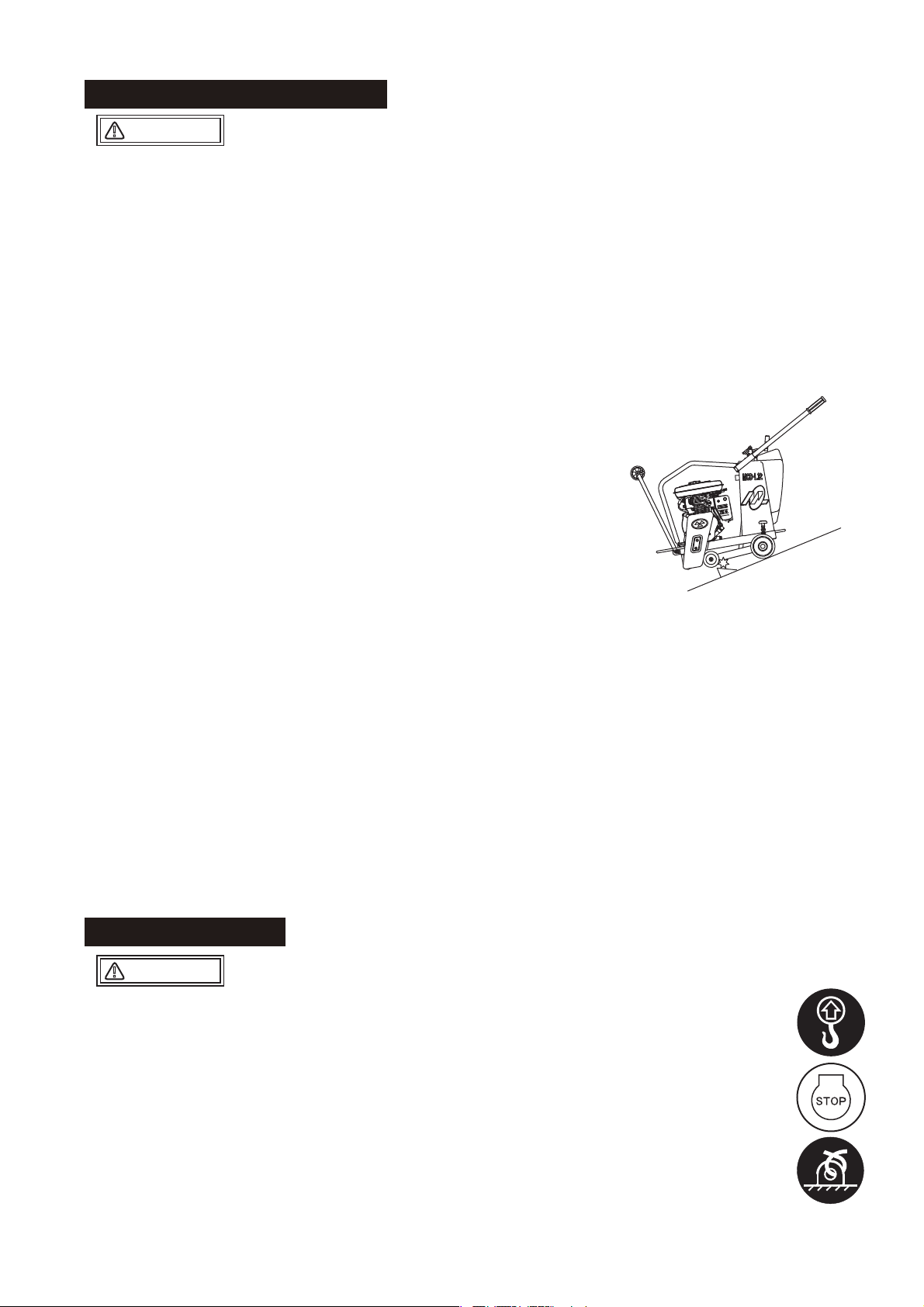
When you work in inclined area, be located in the upper part of the slope for machine
by all means, and let machine face straight it below for a slope, and work.
When put ring stopper, never go in the front side of the machine. When machine has
begun to move by any chance. There is the danger of serious injury or decease, by
the physical truncation with blade and the conflict of machine.
If hand touches the blade when put ring stopper, there is danger injured seriously. Put
ring stopper from the non blade cover side of the machine by all means.
In case of stop, when water is in the water tank, the center of gravity rises and the
balance worsens . Even if you put ring stopper to the front wheel at the time, it is very
dangerous that the front wheel climbs over ring stopper and begins to move. In this
case pull water out of the water tank by all means.
When a road surface gets wet in inclined area, ring stopper in itself slips depending
on an angle, and effect is gone. Stop on the dry road surface by all means, when you
stop it in inclined area out of necessity.
Do not work on blade installation disassembly in inclined area, because it is
dangerous.
Do not work on to cross the slope. There is danger that tumble of the machine or the
damage of the blade cause a serious accident.
Be sure to work with sling by crane license holder.
Before work of lifting, check any damage of body parts (especially, Lifting hook, etc)
or looseness / omission of screws, and be sure safe.
Stop the engine at the time of the lifting, and close the fuel cock.
Use enough strength of wire rope.
The work of lifting uses only one-point lifting hook, and do not lift in other point
(handles).
Never put any person or animal under the lifted machine.
For safety, do not lift up the machine more than required height.
Stop the machine at flat space. When you stop machine in
inclined area out of necessity, lower straight machine after
having stopped the engine by all means, do ring stopper to the
front wheel for safe retention by all means. When be collided by
an automobile and be shaken in right and left, even if you put on
ring stopper down the front wheel, the machine climbs ring
stopper and begins to move, and be careful this risk is very likely.
Even if you put on ring stopper down the back wheel, there is not
effect. In addition, a parking brake of the rear wheel is not a thing
to guarantee certain fixation of the machine. Use ring stopper for
a front wheel on the occasion of a stop by all means.
4.5 Precautions During Work
4.6 Lifting Precautions
䖃
䖃
䖃
䖃
䖃
䖃
䖃
䖃
䖃
䖃
䖃
䖃
䖃
䖃
䖃
䖃
䖃
䖃
DANGER
䟿
DANGER
䟿
Precautions in inclined area

5
Stop the engine at the time of transportation.
Carry it after engine and body got cold well.
By all means drain fuel before transporting the machine .
Fix the machine well not to move and fall down.
Appropriate maintenance is always required for safety operation and to maintain
performance of the machine. Pay full attention in the condition of the machine, and
maintain good condition. Especially improper maintenance of lifting-related part
becomes cause of serious accident.
Do work after lower temperature of machine. Especially muffler becomes high
temperature, and there is danger that burn itself. In addition, be careful not to burn
itself enough, because engine or engine oil become hot.
Do the check alignment in situation that stopped engine by all means. There is badly
injured danger when you are rolled up in a reel.
After maintenance fulfillment, check the installation of safety protection parts and
safety of the machine. Especially, check bolts and nuts thoroughly.
When you do maintenance with dismantlement, refer to maintenance manual
regularly, and work safely.
4.7 Precautions In Transportation / Safekeeping
4.8 Precautions In Maintenance
4.9 Installed Place Of Every Decal
䖃
䖃
䖃
䖃
䖃
䖃
䖃
㻡
10
14
5
10
13
11
12
6
21
㻺㻻㻚 㻼㻭㻾㼀㻛㻺㻻㻚 㻼㻭㻾㼀㻌㻺㻭㻹㻱 㻽㻓㼀㼅 㻾㻱㻹㻭㻾㻷㻿
㻡㻥㻞㻜㻝㻙㻜㻝㻞㻜㻜 㻰㻱㻯㻭㻸㻘㻌㻳㻾㻱㻭㻿㻱㻌㻛㻺㻼㻙㻝㻞㻜
㻢㻥㻞㻜㻝㻙㻜㻥㻢㻥㻜 㻰㻱㻯㻭㻸㻘㻌㻱㻹㻮㻸㻱㻹㻛㻯㼁㼀㼀㻱㻾
㻝㻜 㻥㻞㻜㻝㻙㻝㻜㻜㻡㻜 㻰㻱㻯㻭㻸㻘㻌㻹㻻㻰㻱㻸㻌㻹㻯㻰㻙㻸㻝㻠
㻝㻝 㻥㻞㻜㻝㻙㻜㻜㻥㻞㻜 㻰㻱㻯㻭㻸㻘㻌㻹㻙㻹㻭㻾㻷㻌㻔㻠㻜㼄㻤㻜㻕
㻝㻞 㻥㻞㻜㻝㻙㻜㻝㻟㻥㻜 㻰㻱㻯㻭㻸㻘㻌㻹㻵㻷㻭㻿㻭㻌㻔㻞㻡㻜㻕
㻝㻟 㻥㻞㻜㻞㻙㻜㻥㻤㻝㻜 㻰㻱㻯㻭㻸㻘㻌㼂㻙㻮㻱㻸㼀㻌㻟㼂㻙㻞㻢㻡
㻝㻠 㻼㻸㻭㼀㻱㻘㻌㻿㻱㻾㻵㻭㻸㻌㻺㻻㻚
㻝㻡 㻥㻞㻜㻞㻙㻝㻜㻝㻞㻜 㻰㻱㻯㻭㻸㻘㻌㻵㻺㻰㻵㻯㻭㼀㻻㻾㻛㻹㻯㻰㻝㻞㻙㻞㻜㻜
㻞㻝 㻥㻞㻜㻞㻙㻝㻜㻢㻥㻜 㻰㻱㻯㻭㻸㻘㻌㻯㻭㼁㼀㻵㻻㻺㻔㻵㻯㻻㻺㻕㻛㻱㼄㻼
㻝
㻞
㻞
㻝
㻝
㻝
㻝
㻝
㻝
WARNING
䟿
CAUTION
䟿

6
4.10 Warning Labels And Information
3$5712
㻰㻱㻯㻭㻸㻘㻌㻿㻱㼀㻌㻛㻹㼂㻯㻘㻌㻹㻯㻰㻌㻛㻱㼄㻼㻘㻱㼁㻌
NPA-1479
NPA-1480
NPA-1468
NPA-1473
NPA-1474
NPA-1481
Decal for new European machine directives
䐟Fire hazard
Stop the engine when refueling. Fire
may occur if a flame is near the tank
fuel port.
䐠Danger: poisonous exhaust gas
Carbon monoxide poisoning may
occuriftheexhaustgasisinhaled.Do
not operate the machine in a poorly
ventilated area.
䐢Lifting by the handle is prohibited.
Due to a falling risk, do not lift the
machine by the handle.
䐣Danger of hearing damage caused
by noise
Always use ear plugs while operating
the machine.
䐤Be careful not to get burned.
Accidental burn may occur if you touch
the hot parts (engine, muffler, etc.)
during operation or immediately after
the machine stops.
䐡Do not go under the lifted machine.
Donotlet people or animals gounder
the lifted machine.
䐥Be careful not to be caught in
rotating parts.
Make sure the engine is stopped when
removing the belt cover during a belt
change.
䐦Read the manual carefully.
Always read the operation manual and
have good understanding of operation
before your work.

7
5䠊APPEARANCE
※Specifications are subject to change without notice.
(mm)
527
1650
930
1030
1630
527
MCD-L14
5.1 Dimensions
MCD-L14 ( with Special handlebar )

8
8
Adjusting bolt & nut
of the belt tension
Blade cover
Sprinkling pipe
Water cock
Recoil starter
Line gauge
Diamond blade
Hook
Handle
Lifting handle
Belt cover
Muffler
Rear wheel
Front wheel
Parking brake
Water tank
Air cleaner
Fuel tank cap
Fuel tank
Throttle lever
Switch
(ON-OFF)
Choke lever
Drain plug
Fuel cock
Starter knob
5.2 Parts And Compornent

9
Manufacturer/
Model
Type
Max. Output
Fuel tank capacity
HONDA, GX200
Air-cooled 4-cycle petrol engine
4.1kW/3600min-1
(5.6PS/3600rpm)
3.6L
※
※
Weight includes weigh of machine, lubricants, 50% of fuel and 50% of water in case with
water tank option.
Specifications are subject to change without notice.
Blade size (Outer diameter)
(10in.) 254mm
(12in.) 305mm
(14in.) 356mm
Maximum cutting depth
70mm
95mm
120mm
Model
Power source ( Engine model )
Dimensions
Overall Length ( on operating )
Overall Width
Overall Height
Operating Weight
Traveling system
Adjusting for cutting depth
Cooling System of blade
Water tank capacity
Blade size and maximum cutting depth ( Axis hole dimension of bladeφ27)
Limitation of Blade size
MCD-L14H
[ with Special handlebar ]
GX200
1650mm [1630mm ]
527mm
930mm [1080mm ]
100kg
Hand push type
Manual lifting screw system
Centrifugal injection type
26L
Under 14in.
6䠊SPECIFICATION
6.1 Main Body
6.2 Engine

䚷㻌㻌㻌㻌Do the check alignment in situation that stopped engine
by all means. There is badly injured danger when you
are rolled up in a reel.
䚷㻌㻌㻌㻌㻸㼑㼢㼑㼘㻌㼠㼔㼑㻌㼙㼍㼏㼔㼕㼚㼑㻘㻌㼍㼚㼐㻌㼏㼔㼑㼏㼗㻌㼕㼠㻌㼍㼒㼠㼑㼞㻌㼠㼔㼑
㻌㻌㻌㻌㻌㻌㼙㼍㼏㼔㼕㼚㼑㻌㼏㼛㼚㼒㼕㼞㼙㼑㼐㻌㼠㼔㼍㼠㻌㼕㼠㻌㼐㼛㼑㼟㻌㼚㼛㼠㻌㼙㼛㼢㼑㻚
㻌㻌㻌㻌㻌㻌
䚷㻌㻌㻌㻌㼀㼔㼑㻌㼏㼔㼑㼏㼗㻌㼜㼛㼕㼚㼠㻌㼎㼑㼒㼛㼞㼑㻌㼠㼔㼑㻌㼣㼛㼞㼗㻌㼟㼑㼑㻌㻎㼑㼍㼏㼔㻌㼜㼍㼞㼠
㻌㻌㻌㻌㻌㻌㼏㼔㼑㼏㼗㻌㼟㼏㼔㼑㼐㼡㼘㼑㻌㼘㼕㼟㼠㻎㻌㼙㼑㼚㼠㼕㼛㼚㼑㼐㻌㼕㼚㻌㻝㻣㻌㼜㼍㼓㼑㼟㻚
ۻ
10
DANGER:
㻹㼍㼤㻚㻌㻸㼑㼢㼑㼘
㻹㼕㼚㻚㻌㻸㼑㼢㼑㼘
㻌㻔㻾㼑㼜㼘㼑㼚㼕㼟㼔㻕 㻻㼕㼘㻌㻳㼍㼡㼓㼑
Fig.1
Engine oil (Fig.1)
With the engine positioned horizontally, check
oil-with oil gauge.
Replenish through filler port as necessary. Use
following oil
(10W-30 is in use when shipped).
SAE#30 (for normal temperature)
SAE#20 (for 10 or lower)
SAE#10W-30
This oil can be used throughout the year
regardless of ambient temperature (up to
ambient temperature -20 䉝㻌).
When it is used in normal temperature, its
consumption tends to increase. Pay additional
attention at the time of daily check. As for quality
of oil, be sure to use SE grade or better.
Degraded quality or decreased quantity may
induce damage by seizure.
Fuel
Use lead-free automobile gasoline. For
replenishment, be sure to shutdown engine and
use strainer provided at filler port. Wipe off any
spilled fuel clean.
V-belt
Check V-belt for any slack or damage. Tension is
proper if the belt bends about 10mm when
pressed with your finger at midway between two
shafts. Retighten as necessary but when
replacing, replace both of them simultaneously.
Place the usable one in stand-by parts. For
adjusting the tension, slide engine longitudinally.
Adjusting the belt
A With 4 bolts removed, take off belt cover.
(Fig.2)
B Loosen 4 engine mounting bolts.
Caution: Bolts should be just loosened;
not removed.
C Rotating it clockwise increases the belt
tension. (Fig.3)
1
2
3
7䠊BEFORE STARTING YOUR OPERATION
Fig.2
Belt cover
Bolt
Bolt
V-belt
Fig.3
Engine mounting bolts
Adjusting bolt & nut
of belt tension

11
Water tank
Use water tank filled with water.
Useful life of blade depends on volume of cooling
water.
Pay attention to the water level.
(Fig.4)
Sprinkling pipe
Open the cock to make sure that sprinkler pipe is not
clogged.
(Fig.4).
Installing the blade:
Disconnect water pipe at the nipple of water tank side.
Remove the blade cover by lifting it upward.
Place flange (IN), diamond blade and flange (OUT)
around the blade shaft in such order, and install
washerbeforetighteningsufficientlywithnut(left-hand
thread). (Fig.5, 6)
Afterinstallingthe blade, replace blade covertobase ,
before replacing water hose to nipple firmly. And
check the cooling water.
Cutting depth adjustment:
To unlock, set the knob to shallow groove.
This will enable you to exactly adjust the cutting depth
by turning the lifting handle.
To lower (feed motion) the machine body, rotate lifting
handle clockwise.
To raise the body, rotate the lifting handle counter-
clockwise.
When decided the cutting depth, set the knob at lock
position for lock the position of machine. (Fig.7)
4
5
6
a.
b.
Caution:
With wrench engaged at designated location of the
blade shaft to lock it, rotate nut counterclockwise to
tighten. (Fig.6)
Fig.4
c.
7
Water Tank
Blade cover
Water Cock
Fig.5
Flange(IN)
Diamond blade
Flange
(OUT)
Washer
Nut
Fig.6
27mm(L14)
Tightening
30mm(L14)
Fig.7
Raise
To lock the lift or lower the machine, set
the knob to deep groove.
To unlock, set the knob to shallow groove.
㻯㼞㼍㼚㼗㻌㻴㼍㼚㼐㼘㼑
㻌㻌㻌㻌㻌㻔㻯㼡㼠㼠㼕㼚㼓㻌㼐㼑㼜㼠㼔㻌
㻌㻌㻌㻌㻌㻌㻌㻌㼍㼐㼖㼡㼟㼠㼙㼑㼚㼠㻕
Lower
(Feed motion)

12
Moveeachoperation lever,and check on creakor
the wobble.
Check bolts and nuts for looseness or any other
abnormality.
Parking brake
There is a parking brake to left back wheel.
Turn a knob to right (a clock direction) and brake
it, and turn it to the left and remove brakes.
Remove brakes before the work. (Fig.8)
8.
9.
Cut depth reading method
Cut depth is distance from the reading point of
Fig. 9 to blade tip.
There is blade tip in circumference of blade.
When you cut asphalt or concrete road with
diamond blade, the line trace (trace of line) of turn
happens on the side surface of blade.
Search the line trace of reading point, and read
distance from circumference to it with the scale of
blade cover. (Fig.9)
Parking brake
10.
Fig.8
11.
Fig.9
Scale
Diamond Blade
Surface
of earth
Circumference
Trace of line
Blade Cover
Cut depth
Reading point

13
Move fuel cock lever with “ON” position.
(Fig.10)
When cold or somehow starting is difficult, turn
choke lever to START position. This is not neces-
sary when engine is warm. (Fig.11)
Move throttle control lever slightly to high speed
side. (Fig.11)
Turn engine start switch to ON position.
(Fig.12)
Hold recoil starter grip and pull it slightly until you
feel light resistance. Pull it strongly there. Be care-
ful not to pull it too hard because it may come off.
Donot releasethe gripfrom thepulled positionbut
return it to starter case before releasing. (Fig.13)
If engine has started, while listening to explosion
sound, slowly return the choke lever to OPERA-
TION position. (Fig. 11)
After started, be sure to run the engine at low
speed for a few minutes.
Itmust be donein coldweatherparticularly. Check
for abnormal noise or gas leak in the meantime.
㻝㻚
㻞㻚
㻟㻚
㻠㻚
㻡㻚
㻢㻚
The exhaust gas from the engine is carbon
monoxide and is deadly.
Do not run the engine in an unventilated
location, such as indoors or in a tunnel.
DANGER:
Because engine turns blade when start,
be careful enough.
DANGER:
Do not allow the starter grip to snap back
against the engine.
Return it gently to prevent damage to the
starter.
CAUTION:
8䠊OPERATION
8.1 Starting Up
IN (ON)
ON/OFF Switch
Fig.12
Fig.13
Starter grip
Throttle control
lever
Fig.11
High speed Low ( Idling )
Choke lever
Choke open
(
OPERATION)
Choke close
(START)
Fig.10
䇾㻻㻲㻲䇿
䇾㻻㻺䇿
Fuel cock lever

14
Alignthebladewith cuttingline.Aligningiseasierifitis
done with the machine lifted.(Fig.14)
With water cock opened, spray cooling water to the
blade. At least 5-6 liters per minute of cooling water
is required.
As the standard, if water mist is being sprayed to the
extent that water does not flow, the cooling will be
sufficient. Adjust the amount of water with cock.
(Spray on a little heavier side when there is sufficient
water.) (Fig.15)
Open throttle lever slowly to set engine revolution to
high speed. (Fig.11)
To cut - in with the blade at the bottom, turn the Crank
handle to clockwise, and cut down while adjustment
the lowering speed so that engine speed is not
reduced excessively. After cutting down, set the knob
to the lock position which located beside of Crank
handle to lock the machine. (Fig.16)
While listening to engine sound, push the machine
slowly for cutting operation.
Caution: Sudden feeding or cutting may
damage blade or decrease durability
of engine, V-belt, etc..
When cutting is completed, turn the lift handle slowly
counterclockwise to raise the machine body.
Close water cock to stop cooling water spray.
Return throttle lever to lower engine speed.
Idle the engine for a few minutes to cool down, then
turn the stop switch to the STOP(O) position.
Caution: Muffler gets hot during operation.
Be careful not to touch it when
operating throttle lever.
Close(OFF) fuel cock lever.
Caution: Immediately after cutting
operation, machine is hot
on the whole. Be careful
not incur a burn.
4.
Fig.15
1.
2.
3.
4.
5.
1.
2.
3.
Fig.14
Blade Cutting line
Gauge
9䠊STOPPING
8.2 Working
Raise
㻯㼞㼍㼚㼗㻌㻴㼍㼚㼐㼘㼑
㻌㻌㻌㻌㻌㻔㻯㼡㼠㼠㼕㼚㼓㻌㼐㼑㼜㼠㼔㻌
㻌㻌㻌㻌㻌㻌㻌㻌㼍㼐㼖㼡㼟㼠㼙㼑㼚㼠㻕
Lower
(Feed motion)
To lock the lift or lower the machine, set
the knob to deep groove.
To unlock, set the knob to shallow groove. Fig.16
Close
Open
Water cock

15
䟿WARNING
Before work of lifting, check any damage of body parts
(especially, Lifting hook, etc) or looseness / omission of
screws, and be sure safe.
Stop the engine at the time of the lifting, and close the fuel
cock.
The work of lifting uses only one-point lifting hook, and do
not the work of lifting in other point (handles).
Use enough wire rope of the strength.
Never put any person or animal under the lifted machine.
For safety, do not lift the machine up than required height.
●
●
●
●
●
●
Be sure to work the license holder of crane
operation and slings.
Do loading and unloading by cranes.
In loading and unloading select a leader,
and work by instructions of a leader by all
means.
Lift the machine with the guard hook by all
means, to hook fittings. Never lift the
machine with handle, to hook fittings.
10.1.1. Lifting work
10.1.2.
10.1.3.
CAUTION
䟿Do not do loading and unloading
that use a gangboard, because it
is very dangerous.
䟿WARNING
Stop the engine at the time of the transportation, and
close a fuel cock.
Remove a blade at the time of transportation by all
means.
By all means drain fuel before transporting the
machine .
Fix the machine well not to move and fall down.
●
●
●
●
10䠊TRANSPORT
10.1 Loading And Unloading
10.2 Precautions In Transportation

16
Clean the machine by removing residual
mortar and water.
Drain water of the water tank and the pipe.
Supply grease to the pillow block and
grease nipple of each part .
Particularly, pillow block of the blade shaft
should be well greased a few times by
means of grease gun after work. (Fig.17)
Be sure to grease the thread portion of lifting
screw as well. (Fig.18)
Put cover so that garbage and dust do not
appear.
Store it in the space which no hit rays of the
sun with a little moisture.
11.1.
11.2.
11.3.
11.4.
11.5. Proper storage:
Drain fuel from fuel tank, piping and
carburetor.
With spark plug removed, drip a few
drops of engine oil into cylinder and
rotate engine manually to let the oil
reach everywhere inside the cylinder.
Pull the recoil starter and leave it where
compression is felt.
Store the machine away, covered and
in such place as it is free from direct
sun, moisture and dust.
Keep the machine indoors without
leaving it outdoors.
Do not overthrew the machine
sideways, and do not keep it.
1.
2.
3.
4.
5.
6.
For long term storage after work;
About engine
For daily and periodical inspection or simple
maintenance services, see engine manual
separated provided.
㻲㼕㼓㻚㻝㻤
ࢢ࣮ࣜࢫ
㹅㹐㹃㸿㹑㹃
Supply grease to the grease nipple of each part .
㻲㼕㼓㻚㻝㻣
Pillow block
of blade shaft
Grease nipple
Blade shaft
11䠊STORAGE
Table of contents
Languages:
Popular Cutter manuals by other brands

US Cutter
US Cutter Titan Assembly instructions

Far Tools
Far Tools TC 180B Original manual translation

Rayco
Rayco RG1645S parts manual

FRONIUS
FRONIUS TransCut 300 Operating instructions/spare parts list

Garde
Garde 181FC12 user manual

Central Pneumatic
Central Pneumatic 90114 Assembly and operating instructions