MIL'S MVX 2 Instruction Manual

- ENGLISH VERSION -
GENERAL INSTALLATION AND MAINTENANCE INSTRUCTIONS
AIRMIL'S G with SCREW compressor
Re ulation by MILLENIUM control device
!"#! $%&'
!()'
- 08/17 – NOTICE N° 515910 VERSION 12 -

Particular maintenance instructions
AIRMIL'S G with SCREW compressors
Re ulation by MILLENIUM control device
Page 1/20 08/2017 Manual N° 515910 version 12
CONTENTS
SECTION 1.
INT ODUCTION 3
1.1.
S
PECIFICATION PLATES
.............................................................................................................................................. 3
SECTION 2.
CHOICE OF OOM 4
2.1.
OOM VENTILATION
................................................................................................................................................... 4
SECTION 3.
DESC IPTION WITH SC EW COMP ESSO 5
3.1.
S
CHEMATIC DIAG AM EXAMPLES
................................................................................................................................ 5
3.2.
D
ESC IPTION OF THE AI P ODUCTION LINE
................................................................................................................. 6
3.3.
D
ESC IPTION OF THE OPE ATION OF THE AI P ODUCTION LINE STA TING F OM TWO COMP ESSO S
............................... 7
SECTION 4.
INSTALLATIONS 8
4.1.
D
IMENSIONS OF COMP ESSO S
.................................................................................................................................. 8
4.2.
D
IMENSIONS OF
FIL2/FIL3
FILT ATION
....................................................................................................................... 8
4.3.
D
IMENSIONS OF
SEC2F/SEC3F
AI T EATMENT UNITS BY EF IGE ATION
................................................................... 8
4.4.
D
IMENSIONS OF
SEC
A
AI T EATMENT UNITS BY ADSO PTION
..................................................................................... 8
4.5.
D
IMENSIONS OF ECEIVE S
........................................................................................................................................ 8
4.6.
D
IMENSIONS FO P ESSU E EDUCING VALVE OUTLET
................................................................................................. 9
4.7.
E
LECT IC POWE SUPPLY AND CONT OL FO SC EW COMP ESSO
............................................................................ 10
4.8.
P
OWE SUPPLY AND CONT OL OF THE AI D IE BY ADSO PTION
................................................................................ 11
4.9.
P
OWE SUPPLY AND CONT OL OF THE
"SECF"
TYPE D IE BY EF IGE ATION
........................................................... 11
4.10.
C
ONNECTIONS TO THE PNEUMATIC SYSTEM
................................................................................................................ 11
SECTION 5.
CONNECTIONS 12
5.1
I
NSTALLATION OF
AI MIL’S
UNITS
,
TYPE
G .............................................................................................................. 12
5.1.
C
OMPÉTENCIES
,
T AINING AND QUALIFICATIONS
......................................................................................................... 12
5.2.
B
EGINNING OF THE WO K
......................................................................................................................................... 12
5.3.
O
PTIONNAL TANK
.................................................................................................................................................... 13
5.4.
P
IPES
,
FLEXIBLE HOSES AND FITTINGS
....................................................................................................................... 13
5.5.
B
AZING OF PIPING
................................................................................................................................................. 13
5.6.
V
E IFICATIONS DU ING AND AFTE THE INSTALLATION OF THE PIPES
............................................................................ 13
5.7.
I
DENTIFICATION AND T ACEABILITY
........................................................................................................................... 14
SECTION 6.
UNNING OPE ATION 15
6.1.
F
I ST STEP
............................................................................................................................................................. 15
6.2.
S
WITCHING ON
........................................................................................................................................................ 15
SECTION 7.
CLEANING AND MAINTENANCE 15
7.1.
S
AFETY VALVE
........................................................................................................................................................ 16
SECTION 8.
ECEIVE S (P OVIDED BY MIL’S) 17
SECTION 9.
T AINING 17
SECTION 10.
CLEANING 17
10.1.
U
NITS CLEANING
..................................................................................................................................................... 17
SECTION 11.
ELECT OMAGNETIC COMPATIBILITY 18

Particular maintenance instructions
AIRMIL'S G with SCREW compressors
Re ulation by MILLENIUM control device
Manual N° 515910 version 12 08/2017 Page 2/20
MEANING OF SYMBOLS USED IN THESE INSTRUCTIONS
)"!!)!#!!)
'!)"*
eading symbol* !'
Warning symbol: ! )" ! "+ ! ,) ")
-!!'%+"-!
'
Danger symbol:!)"!.%/0100)"2!3#-45# !3#!!
! ,)6 - #! - ! !' ! )" " "+ ")
#7-!!'- )!#7""+'
Environmental protection symbol: This symbol serves as a reminder to sort waste during
maintenance operations, to store it in a safe place, and to dispose of it with due care for the
environment.
Dustbin on wheels barred of a cross symbol: ! )" ! ! ( ! "
!##!#",+'
Non-ionizing radiation hazard symbol*
!- 7-83-
General remark:
% #!!6"-!97# )!(
+ ::;096 + ! 6 #! )6 ( ! +
:0;16+('
! 6 when installed in accordance with these instructions6 ) #! ! + )
".+!'
<#+6)#! !#!))+"
#!-)"7+*-"7! ="'
To ensure personal safety and to avoid any damage to equipment, it is essential to follow the
instructions contained in this document and any other documentation provided with the device,
and particularly the instructions on “Safe Practice”.

Particular maintenance instructions
AIRMIL'S G with SCREW compressors
Re ulation by MILLENIUM control device
Page 3/20 08/2017 Manual N° 515910 version 12
SECTION 1. INT ODUCTION
Please read the start-up instructions carefully before commissioning the air plant. Damages
resulting from improper implementation or installation shall not be covered by the warranty.
%6 )"( 2 (4 )
( - ) 6 # ! - ! ! #!! 7 !
! ! )6)+!('
1.1. Specification plates
Station AI MIL'S
AI MIL'S type
Model
egulation type
Serial number
Date of fabrication
Power of the plant
Power supply
Maximum pressure
Fluid group II
Dryer
Type
Model
Serial number
Date of fabrication
Power supply
Maximum pressure 16 bar
Fluid group II

Particular maintenance instructions
AIRMIL'S G with SCREW compressors
Re ulation by MILLENIUM control device
Manual N° 515910 version 12 08/2017 Page 4/20
SECTION 2. CHOICE OF OOM
! " 6 8!6 86 + #! !
!""#>9>0:9'
+")!"(+'
! #- "3! *
! #- "3! *
?@A=:::=B;::@11:=/
C=:C
?@D+2E!4
A@9-)27F4
C@ "#!
:@D!)92G'E'H
8
4
=*9#;'7F
C-"@:9
?@11:=;'@0E!
:
!"!!! #=B
=
@?@0@:'00
D=B;::B=B;::
2.1. oom ventilation
! !-! !+ # #+)
2@B4I=''J'
Example:
The compressor ventilation flow being of 2500 m³/h (= 0. 94 m³/s), the grid section will be 0. 94/3 = 0.2 m²
Particular maintenance instructions
AIRMIL'S G with SCREW compressors
Re ulation by MILLENIUM control device
Page 5/20 08/2017 Manual N° 515910 version 12
Compressor
type Power (kW) Heart release
(kCal/h)
Air inlet section
(m²)
Exhaust fan
(m³/h)
Exhaust air
duct (mm)
MVX 2 2,2 1 892 0,10 1 000
MVX 3 3 2 580 0,10 1 200
MVX 4 4 3 440 0,10 1 500 150 X 340
MVX 5 5,5 4 730 0,20 2 000 250 X 360
MVA8 7,5 6 450 0,25 3 000 250 X 630
MVB 12 11 8 340 0,35 4 500 350 X 600
MVB 16 15 10 576 0,45 5 500 350 X 650
MVC 19 18,5 18 920 0,60 8 000 350 X 650
MVC 23 22 18 920 0,50 7 500 650 X 650
MVD 31 30 25 800 0,70 10 000 650 X 650
MVE 38 37 31 820 1,00 13 500 700 X 700
MVE 46 45 38 700 1,20 16 500 700 X 700
HANDLING : !("!")! -+'
!!- !!+") !+('
<!- -! --- -!76 -6
!(7'
!!=-" "-+-- !#7'
K2#6#6''4"7'
+"-'
-!/82L88B46%K::1B6%KB;82L814"!
K
6-"8)-('
SECTION 3. DESC IPTION with screw compressor
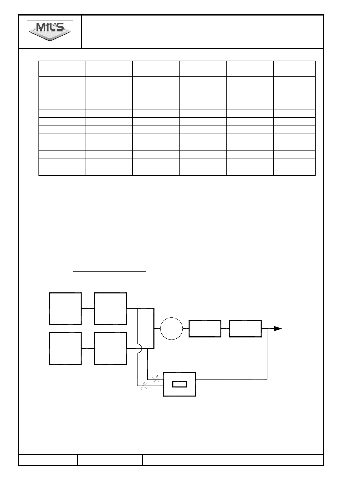
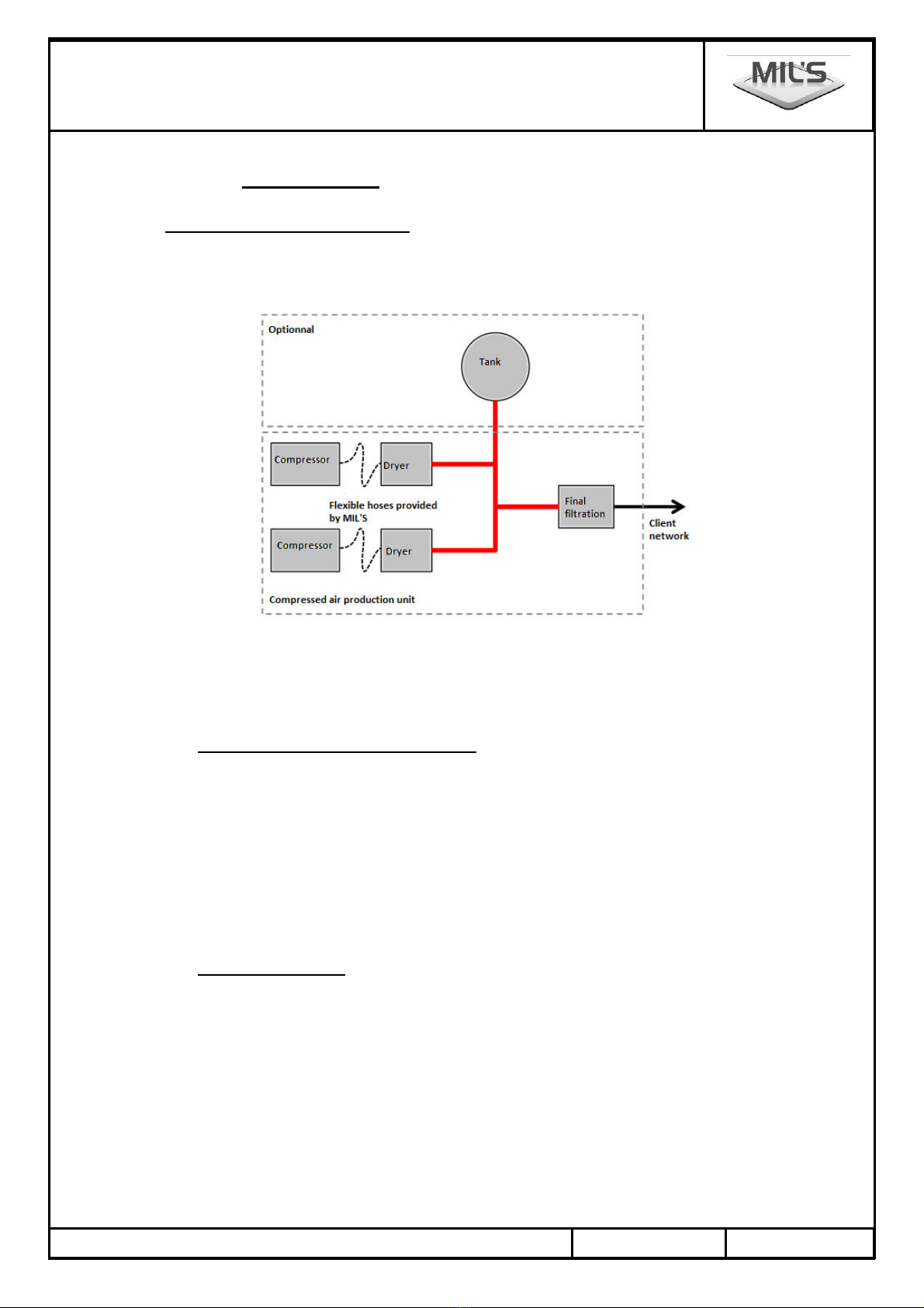
3.1. Schematic diagram examples
3.1.1. Mechanical architecture: each compressor associated with a air treatment unit
$%/%$
9
9
9F
9K$AK
.")
8
8 -
8
9F
9K$AK
.")
8
8
8 -
+ A
.9 %/% /FKH
/FKH/K
9+
M%K//K

Particular maintenance instructions
AIRMIL'S G with SCREW compressors
Re ulation by MILLENIUM control device
Manual N° 515910 version 12 08/2017 Page 6/20
3.1.2. Mechanical architecture: two compressors associated with an air treatment unit
9
8
$%/%$
9
9F
9K$AK
.")
8 -
8
+ %/% /FKH
9+
M%K/
/K
/FKH/K
A
.9
9F
9K$AK
3.2. Description of the air production line
3.2.1. Compressor
9"#'!B)#! +*1"6"
"'!)(#!!'
3.2.2. Air treatment unit
!")!-#!'
! -!() !'
• *%)*
⇒ %*NAN >NON '
⇒ %B*NAN >NON >N9<N2"4 '
!NAN # !P'
!NON # !:':P'
!N9<N #! !+!6:'::B'
• ") -*
⇒ 9*NAN >)") ->NON '
⇒ 9B*NAN >)") ->NON >N9<N '
!)") -7"#!#>B9'
• ")*
⇒ 9*NAN >NON >)")>NON '
⇒ 9B*NAN >NON >)")>N9<N >NON '
⇒ 9B<*N9N >NAN >NON >)")>N$9N >
NAN
⇒ 9<*N9N >NAN >NON >)")'
!")7"#!#+#!809
-'
%"" !)-)!+ '
3.2.3. Receiver
!6 "-6!+'
!++6-! !'!)"-+3'
9B9BB<<!6)!+
!)'
!)(#! )++6--++'
#+"" '
3.2.4. Pressure reducer
F!#")6-3!#7"#1
:"'
Particular maintenance instructions
AIRMIL'S G with SCREW compressors
Re ulation by MILLENIUM control device
Page 7/20 08/2017 Manual N° 515910 version 12
3.2.5. Final iltration
!!#7!+'
3.2.6. MILLENIUM control device
% ! 6!6!&$%/%$+'
!)'
# 6 ) !+ ! +* # ! "# ! #
6- !!!- '
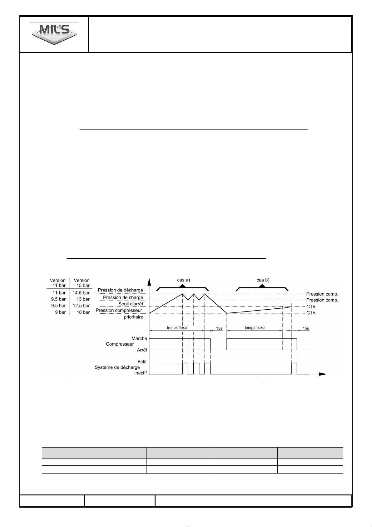
3.3. Description of the operation of the air production line starting from two compressors
! !"!+'
%#)7 !" !+'
3.3.1. Regulation compared to the pressure
!-NQKN-'
F! ! ! ! ! 6 ! ! ) #)
'! QK'
3.3.2. During the FLEXO time :
!#)-! !9'
%=!!!'% !!+ !!!+ 6!!
) !- !+-!= !6
!#!! 6!) !-"-+!+
'''
3.3.3. When the FLEXO time is inished:
!#*
4 !!+ !9!-!!!!!
!-#! )")6!-+
!) !)'
"4 !!+ !9#!!!!
F!!!+ !9!!!! 6!-
#!-+!) !)'
F!!=)6!+ !'NQKN1'
% ! -- # ! ! ! 6 ! ! 8")
'
Maximum pressure of compressor 1" " "
Pressure of discharge 1" '" B"
Pressure of load ;'" 1'" :'"

Particular maintenance instructions
AIRMIL'S G with SCREW compressors
Re ulation by MILLENIUM control device
Manual N° 515910 version 12 08/2017 Page 8/20
3.3.4. Compressor alarm
!6-!"!$%/%$+'
!!)! ! #-*
$,6
!-!6
9# 6
9 -#!!(#'
% 6!!
#'
-!'
%+7- 6!)!#"7)! :'
3.3.5. Go orced by button with key
%!"=6!"#!7) !'
! !- !")")8!$%/%$+'
K!7)!"+*"#!#)! - !"=
"-)+- ! '
! )#+"7#+ !!'
-!
3.3.6. Values o the initial thresholds
Maximum pressure of compressor 1" " "
Threshold of stop pressure " " '"
Threshold of the 1
st
compressor ;" 1" :"
Threshold of the 2
nd
compressor '" '" '"
3.3.7. Stop o the compressor
F!!- !(")!$%/%$+")!KK ""-
!6!!) !--:!#
)'
!)-!#'
EME GENCY STOP:
To use the emergency stop only in the event of extreme need because it stops the compressor
brutally and if the compressor is in load, a part of oil can, in the long term, go up by the suction.
%!6"!KK "!'
SECTION 4. INSTALLATIONS
4.1. Dimensions of compressors
! !!!'
4.2. Dimensions of FIL2/FIL3 filtration
! !%B !!'
4.3. Dimensions of SEC2F/SEC3F air treatment units by refrigeration
! !9B") -!!'
4.4. Dimensions of SEC A air treatment units by adsorption
! !9")!!'
4.5. Dimensions of receivers
!- - ++'

Particular maintenance instructions
AIRMIL'S G with SCREW compressors
Re ulation by MILLENIUM control device
Page 9/20 08/2017 Manual N° 515910 version 12
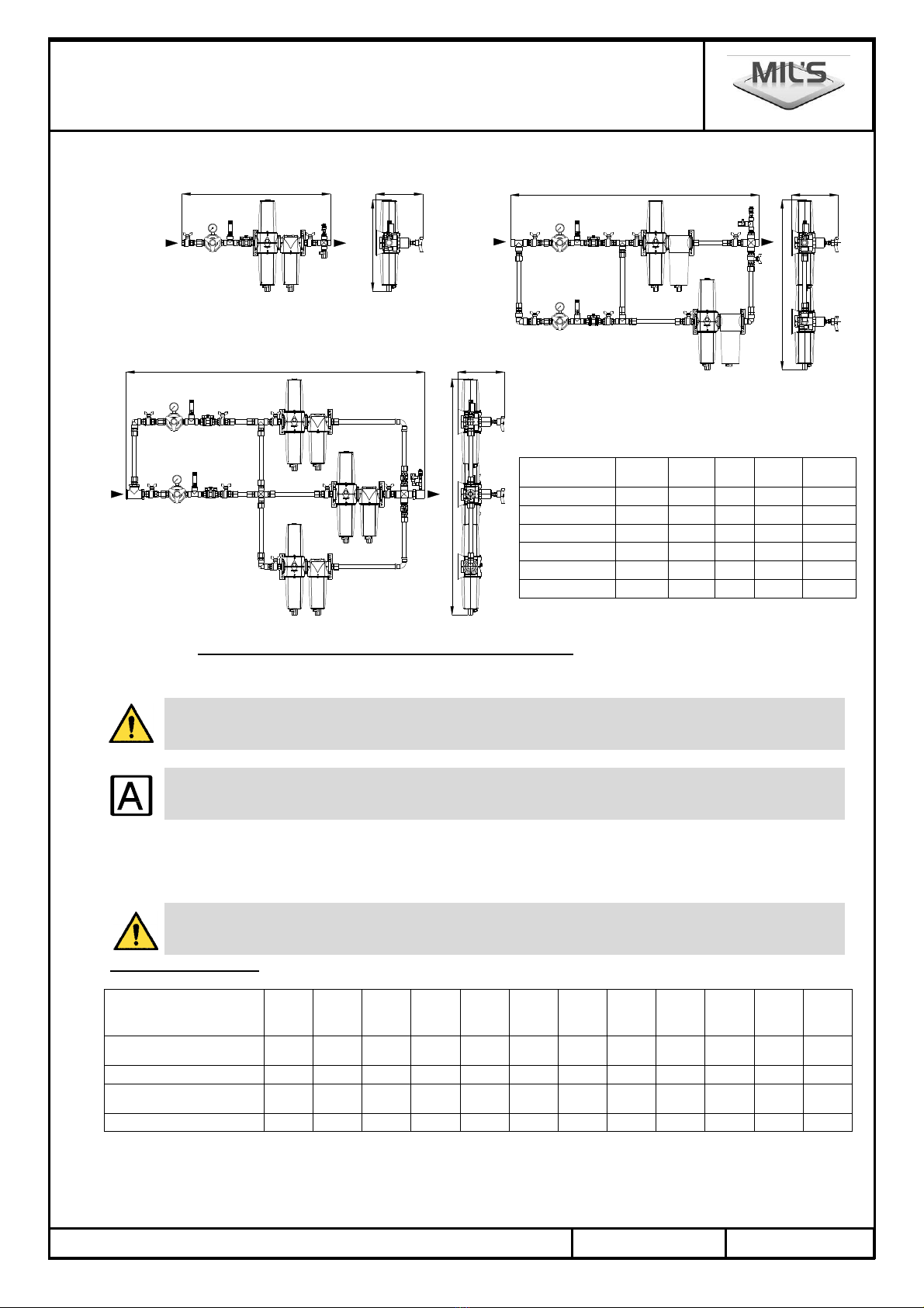
4.6. Dimensions for pressure reducing valve outlet
4.6.1. Pressure reducer alone
BP300 BP500 / BP800
4.6.2. Simple, parallel duplex and parallel triplex inal iltration
CMP 53 S CMP 106 DP CMP 159 TP CMP 162 S CMP 324 DP CMP 486 TP
Flow rate at 9 bar (m³.h
-1
53 106 159 162 324 486
inlet / outlet diameter 1/2" 3/4" 3/4" 3/4" 1" 1"1/4
Composition
Filter CHA/MC 1 x CHA/MC48 2 x CHA/MC48 3 x CHA/MC48 1 x CHA/MC145 2 x CHA/MC145 3 x CHA/MC145
Filter PAR 1 x PAR72 2 x PAR72 3 x PAR72 1 x PAR217 2 x PAR217 3 x PAR217
R
O
R
9
R
9
O
R R
O
R
9
Simple version parallel duplex version
parallel triplex version
4.6.3. Simple, parallel duplex or parallel triplex release lines
DCMP 53 S DCMP 106 DP DCMP 159 TP DCMP 162 S DCMP 324 DP DCMP 486 TP
Flow rate at 9 bar (m³.h
-1
53 106 159 162 324 486
Inlet / outlet diameter 1/2" 3/4" 3/4" 3/4" 1" 1"1/4
Composition
Regulator 1 x BP300 2 x BP300 2 x BP300 1 x BP500 2 x BP500 2 x BP500
Filter CHA/MC 1 x CHA/MC48 2 x CHA/MC48 3 x CHA/MC48 1 x CHA/MC145 2 x CHA/MC145 3 x CHA/MC145
Filter PAR 1 x PAR72 2 x PAR72 3 x PAR72 1 x PAR217 2 x PAR217 3 x PAR217
A B C ØE Weight
kg
CMP 53 S 492 447 110 1/2" 3
CMP 106 DP 778 752 110 3/4" 7
CMP 159 TP 864 1047 110 3/4" 11
CMP 162 S 577 506 135 3/4" 6 5
CMP 324 DP 904 941 135 1" 15
CMP 486 TP 1153 1306 135 1"1/4 22
.=
Particular maintenance instructions
AIRMIL'S G with SCREW compressors
Re ulation by MILLENIUM control device
Manual N° 515910 version 12 08/2017 Page 10/20
9
O
R R
O
9
R R
Version triplex parallèle
R
Version simple Version duplex parallèle
R
O
9
4.7. Electric power supply and control for screw compressor
See the electric diagram attached to this manual for the connections
All operations on the air plant shall be performed with the air plant switched off.
Connection shall be made by the exploiting.
In order to discharge a risk of loosening of electric connections with the vibrations during
transport, we advise you to check the tightening of electric connections before the initial start-up.
⇒ 9!7!!+-!!!!+- )#)'
⇒ ! ! " )6 #6 ") B # > - 2 ! -
))4")86 !2 !-4'
Protect all power leads located upstream by an over-current protection device in compliance with
the legislation and regulations in force in your country.
Protections in Ampere
Screw compressor
T I 400V 50Hz
MVX
2
MVX
3
MVX
4
MVX
5
MVA
8
MVB
12
MVB
16
MVC
19
MVD
23
MVD
31
MVE
38
MVE
46
A#7F
! ' B 0 ' ' B: B 0
-! 0' ;'0 1'0 :'1 B: 0 0B ; 0
FS
! ' ' ' ' 0 ; : ; ; B B
A : ; ; ; 0: ;B ;B 1: :: ::
!#-+
'
+6!!" ")7-#!!#+'
!)*
8 !#)
A B C ØE Weight
kg
DCMP 53 S 691 447 171 1/2" 4 5
DCMP 106 DP 1115 752 171 3/4" 10
DCMP 159 TP 1266 1047 171 3/4" 15 5
DCMP 162 S 825 506 260 3/4" 9 5
DCMP 324 DP 1375 941 260 1" 21
DCMP 486 TP 1650 1306 260 1"1/4 31
.=
A=+
+
A=+
Particular maintenance instructions
AIRMIL'S G with SCREW compressors
Re ulation by MILLENIUM control device
Page 11/20 08/2017 Manual N° 515910 version 12
8 !-!
8 !
8 !#!
Alarm report:
!"#"")!!- !
%'
<!#--! '
• !6
• !-#!B:DT:<36+='S">-'
• 9!-*
#20=:'S4
• #*B*'
• #*1*)!'
4.8. Power supply and control of the air drier by adsorption
%! )")6!)#!!'
!- #-'
• 9!-"=*
.)20=:'S>-4* #>-*)#)'
#*0 !)'
20 )0OO )O4
OHK2!) !)420=:'S>-4
#>-*#) OHK'
# 01'
4.9. Power supply and control of the "SECF" type drier by refrigeration
!#) !)'!- !") -'
!) ")
4.10. Connections to the pneumatic system
4.10.1. Pneumatic connection to the MILLENIUM system device
% !#!!2LB''46#'0=;NN
!! !"='
/O*NN+#!!"='!)(#!':'033+")8
"#!#'
% 6'0=; !-9'
% ! 6!'0=;!#79'
4.10.2. On the network side
24 24!+ ="'
"#!!!"")- ="'
4.10.3. Drain o condensates
K !!#!"6! '
!)")! " !)") -'
! 2)6AO4( #!!#!!#!
)'%!!'
In order to respect the environment, these effluents must be treated before going down the
sewerage system (separation of the oil and water phases, using an OWAMAT separator).
Note : for installing the OWAMAT separator (option), refer to the OWAMAT installation and
operation manual attached hereto, and strictly comply with all recommendations.
Particular maintenance instructions
AIRMIL'S G with SCREW compressors
Re ulation by MILLENIUM control device
Manual N° 515910 version 12 08/2017 Page 12/20
SECTION 5. CONNECTIONS
5.1 Installation of AI MIL’S units, type G
! %$%U 7- M - + #!! "
")!!'
!-"#!#!"*
!-!"#!!)+")!MIL’S SAS9)'
!27!-4"#!)6! !7!
= !!6! !+'
! #-!(7 !7)#!!""+")!
!-*
5.1. Compétencies, training and qualifications
!!)""+!!)!+-7#- -6!
!7'!+ 7#-"")6--
='
!#7-!,""66!!)!+!(-)
( 2 4'
%+!!*
• ( )!#!"3-#!!( !ISO 135856
• ( )!"3-#!EN 131346
• 7 - ! ( ! )'
! " ! ( ! $%U 9)6 ! 9 !6 !
") ! '
5.2. Beginning of the work
F7)"-#!!- F7!3 !'
% #7 !# )6 ! "8 $ # ! !# !
"!'!!#"!!!#!3'
! "8 ) #! ! ( ! !! "! !)-
6)-#7")'#"
!7 "8 ('
O ! !6!"8+ ) -)6+
6 "6!"")=)'#!!!+-7--"'
! "8 " ) +-6 - #7 6 -- ! "
- -!28-4'
#7678)"'
!""#!=)-+6#!!(
NF EN ISO 15001'
Particular maintenance instructions
AIRMIL'S G with SCREW compressors
Re ulation by MILLENIUM control device
Page 13/20 08/2017 Manual N° 515910 version 12
5.3. Optionnal tank
% !7!- )-!-76"!#7- !
) " ! 9 7- #! + 2014/68/UE 2( 4
2014/29/UE2+4'
!7"(#!*
• +++6
• 97 )++#!+2014/68/UE2(46
• 6
• ++'
5.4. Pipes, flexible hoses and fittings
!-" #!NF EN 13348'
!"! !"'!-6
! B 2 UU V =4 6 ! - + :0;16 !
- 0'B'
! -!"#!EN 1254-1 EN 1254-4'
% #-!6!)"#!NF EN ISO 5359'
! " + 6 " - !
'
!6 ! " " #! ' ! - !
-'
A !- ! !-"")!
( !$%U9)6!9!! ") ! '
!-!-!+ ! + 6
! ")'
!- - !" "EXCLUSIVELY #!
!7 !+-'
! ! - " - A ! "
( § 11.1 NF EN ISO 7396-1'
!"#!!( § 11.2 NF EN ISO 7396-1'
! !#7"-#!!-
'
!"-!)-.
5.5. Brazing of piping
F!!= !! - 6 ! -""3
#'% 6!("!;::9'!
") '% +)6!)"#!ISO 17672'
.-!"3-#- ! -6! !")-#!+
-!7 !+-'
! "8 ) "3- ! ! ") ! !!
"!'
5.6. Verifications during and after the installation of the pipes
8+ "-!6)++ !"3-
*
• !" =-!"3-6
• ) !"+!-6
• !" !,6
• !" 8 6
! piping and components of the network which provide the link between the various components !
"",-!'!-2!
!4'!""#!" !*
92"4 Test pressure (bar)
16.5
22.5
! !+ "+'

Particular maintenance instructions
AIRMIL'S G with SCREW compressors
Re ulation by MILLENIUM control device
Manual N° 515910 version 12 08/2017 Page 14/20
! )- + " -'NF EN ISO 7396-1"
-")!"'
! !+ "7'
5.7. Identification and traceability
!"") ! #-'
• 6
• -76
• )++!#76
• D+2 !)""!"4'
!"8MUST!"!" !"+! 8+ '
! "8 " ! " ) ! ++ 7 #! !
-2ruling of December 10, 20044 '
Particular maintenance instructions
AIRMIL'S G with SCREW compressors
Re ulation by MILLENIUM control device
Page 15/20 08/2017 Manual N° 515910 version 12
SECTION 6. UNNING OPE ATION
6.1. First step
⇒ 9!7!+ '
⇒ O -!(6 !-!!
2#6.K$%&)69)6'''4'
⇒ !KK #!K2K 4'
6.2. Switching on
⇒ ! #! ! N%N 2K4 ! NN6 ! NN ' 9!7
) ! ! 2 ! 4' % & -6 !
#!!-)"#!#'
⇒ !NN'
⇒ %! +6#!!+#;"""
!'
⇒ -! -#!!!'
⇒ !7! !-*
!#76
97!)#-!6
!!76! !++'
SECTION 7. CLEANING AND MAINTENANCE
IMPO TANT:
For this operation, use all necessary protective measures (gloves, mask, overalls etc.) then
destroy contaminated consumables (antibacterial cartridges, condensates etc.) in according with
that country’s applicable laws (regulation incinerator).
Maintenance is to be entrusted to trained and approved personnel by the exploiting, with all
necessary knowledge and acquainted with best practice.
Not to carry out maintenance operations when the device is in use.
If the spare parts used during maintenance operations are not corresponding to the
manufacturers' requirements, the manufacturer declines all responsibility in the event of an
incident.
The modification of the central units is forbidden.
Modification of the device is forbidden without the approval of the manufacturer.
If the central is modified following manufacturer agreement, a control and a suitable test must be
realized to make sure that the central is always safe to use.

Particular maintenance instructions
AIRMIL'S G with SCREW compressors
Re ulation by MILLENIUM control device
Manual N° 515910 version 12 08/2017 Page 16/20
+ 7 - + ( " - ! "
+")! '
6
months
12
month
18
months
24
months 3 years 5 years
COMP ESSO !-
ECEIVE
9-) !-
P ESSU E INDICATO (sensor, pressure gauge)
$+)!7 W
A--!- W
ELECT ICAL CABINET
9- "! W
9!7!!" W
9!7! W
9!7!) ! W
HOSE O ILSAN UNDE P ESSU E
K+!7 W
9!- W
SAFETY VALVE
9!- W
D AIN HOSE O ILSAN (optional)
K+!7 W
9!- W
OWAMAT (optional) (see manual) !-#!#"
FILTE S 6
months
12
months
18
months
24
months 3 years 5 years
PF FILTE
9- W
9!-!! W
SUB FILTE
9- W
9!-!! W
CHA (carbon) FILTE
9- W
MC FILTE
9- W
PA FILTE
9- W
BAC FILTE
9- W
AI D YE BY ADSO PTION 6
months
12
months
18
months
24
months 3 years 5 years
!-
AI D YE BY EF IGE ATION 6
months
12
months
18
months
24
months 3 years 5 years
!-
7.1. Safety valve
F! ++ #! !- " 6 ) ! ++
!-'/#!-=6=+ "6!!'
O !6!- +('
/+ #! ! ++6 + ! & 6 ) , )
'/!!!7! ++'
$7!! &+-'
$!++ -'9!7!!=! ! -
")"7!+-'
7!! )++-#7-6!")'
!6 ! ++ ) - ! + ! 7"5 ! " #! 7- !
"#1::X !++"'!++)6
" 6 ! ) !+! " ! 7"

Particular maintenance instructions
AIRMIL'S G with SCREW compressors
Re ulation by MILLENIUM control device
Page 17/20 08/2017 Manual N° 515910 version 12
-!'!"! ,'F!6) !
()'
SECTION 8. ECEIVE S (provided by MIL’S)
Service conditions*!+ !+ '
!-!+=!+'
! #-=!"#!*
:;::* @8:9 ;:::::* @:9
=@;:9 =@:9
These temperature values are given according to the capacity and only apply to the pressure
receivers used with our AI MIL’S products.
Purpose of use*!-+--'
Installation and maintenance:
!+"6!#!!7)++
!+=-! +5"-'
!7")'
%#)"2=! ++67-++6'''4&"+!
+6 -+'
!76!+"+-)-!- !)
#!'
!"-)#!(26-'''4'
=- - +"#!7-+
+"6+8+"'
!" !+#!+!#-! !+6- '
% -6+6#)#!!- #!!
7!)'
!(" #!! &+'
In complement of the indications hereafter, refer to the instruction manual provided with each receiver.
!+!" 3-! '
(!- -)7-!+'
O -!!+67
!!)2(!!4'
/ ) #- 2-6 !- #! 6Y4 ! !
+'
! !+#!!"#! ="+
+"'
7!!+#)+#!)-+'
%!+ - !+6!7")-6!!+" )'
SECTION 9. T AINING
% ! !=)-6!$%&9) #-
! !('% !#7-!'
SECTION 10. CLEANING
10.1. Units cleaning
Do not use corrosive product
% !)(-6!'
!###!)!'
6#"7 '
()*('

Particular maintenance instructions
AIRMIL'S G with SCREW compressors
Re ulation by MILLENIUM control device
Manual N° 515910 version 12 08/2017 Page 18/20
SECTION 11. ELECT OMAGNETIC COMPATIBILITY
!%$%U#7#!$%/%$--$9'
!%$%U#7#!$%/%$!"+-!$9
(,! #-"
Guidance and manufacturer’s declaration – electromagnetic emissions – for all ME equipment and ME systems
!%$%U#7#!$%/%$
!-+ "#'!
! !%$%U#7#!$%/%$
!!!
-+'
Emissions testComplianceElectromagnetic environment Tguidance
9%A M
!%$%U#7#!$%/%$
-)) '! 6
+)#7)) ")
('
9%A 9O
!%$%U#7#!$%/%$
"
"!6-"!
!)!"#+-#)
#7!"-
<
%9;:::8B8 9
D-
7
%9;:::8B8B
9
Guidance and manufacturer’s declaration – electromagnetic immunity - for all ME equipment and ME systems
!%$%U#7#!$%/%$
!-+ "#'!
! !%$%U#7#!$%/%$
!!!
-+'
Immunity testIEC 60601 test levelCompliance levelElectromagnetic environment Tguidance
!-2.4
%9;:::808
Z;7D
Z17D
B:D:<3
Z;7D
Z17D
!"#6'%
+#!)!6!
+!)!"B:X'
"
%9;:::8080
Z7D #)
Z7D
B:D:<3
7D #)
Z7D
$#()!"! )
!+'
-
%9;:::808
Z7D2424
Z7D24!
B:D:<3
Z7D
Z7D
$#()!"! )
!+'
D-6!
+-+
#)
%9;:::808
[ X U 2\ X
U4 :6)
0: X U 2;: X
U4 )
: X U 2B: X
U4 )
[XU2\X
U4
AB:D:<3
:D-:
D-::
;D-
:D-
$#()!"! )
!+'% !
!%$%U#7#!$%/%$
(-
#6!
!%$%U#7#!$%/%$
"# "
#)")'
A# ()
2:;:<34
-
%9;:::8081
B B :<3
A# () - ! "
+ ! )
)!+'
/"-
'
/K*U!''+- !+'

Particular maintenance instructions
AIRMIL'S G with SCREW compressors
Re ulation by MILLENIUM control device
Page 19/20 08/2017 Manual N° 515910 version 12
Guidance and manufacturer’s declaration – electromagnetic immunity - for ME equipment and ME systems that are not life-
supporting
!%$%U#7#!$%/%$
!-+ "#'!
! !%$%U#7#!$%/%$
!!!
-+'
Immunity testIEC 60601 test levelCompliance levelElectromagnetic environment Tguidance
9
%9;:::808;
%9;:::808B
BD
:7<31:$<3
BD
1:$<36M<3
BD
BD
A" "
(!")
! %$%U #7 #! $%/%$
6 - "6 ! !
! ( " ! ()
!'
ecommended separation distance
d = ';]P
d = ';]P 1:$<3^1::$<3
d = 'BB]P1::$<3^6M<3
#! P ! = # -
! # 2F4 - !
d !
24'
-! = 6
")-+)24
!"!!+!
()-'24
% ) ! +)
(7#!! #-)"*
/K1:$<31::$<36!!-! ()-'
/K!-))'-- ")"
6",'
24 -! = 6 ! " 24 ! " 6
6 $ $ " D " " !) #! )' !
-+ =6-+)!"'% !
-! ! #!! ! %$%U #7 #! $%/%$
= ! "
+"+6!%$%U#7#!$%/%$
!""++ )'%
" "+6 )")6!8- -!%$%U
#7#!$%/%$
'
24K+! ()-:7<31:$<36 -!!"!BD'
This manual suits for next models
11
Table of contents
Other MIL'S Medical Equipment manuals

Popular Medical Equipment manuals by other brands


Servox
Servox Digital First steps

Inspire
Inspire SLEEP REMOTE manual

Drive Medical
Drive Medical 15003 Owner's assembly and operating manual

Agilent Technologies
Agilent Technologies 7697A Operation manual

bort medical
bort medical SellaTex Plus quick guide

St. Jude Medical
St. Jude Medical TactiSys Quartz Equipment user manual


