Miller ArcReach User manual

Quick Setup Guide
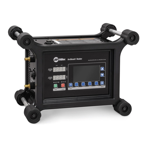
ARCREACH® HEATER

ArcReach®Heater
2
The Complete ArcReach®
Heater System
or
a. Power Source
b. ArcReach Heater
c. Extension Cable and Series Adapter
d. Thermocouples (TCs)
e. Insulation Fault Detection Magnet
f. Preheat Insulation
g. Air-Cooled Quick Wraps
h. Air-Cooled Cables
i. Preheat Cover
c
b
g
d
e
f
d
a
hif

Quick Setup Guide
3
Step 02.
Connect the ArcReach®Heater to a
compatible welding power source.
Attach a weld cable to the “Electrode” (positive) connector
on both machines. Using another weld cable, do the same to
both machines’ “Work” (negative) connectors.
Do not use worn, damaged or repaired weld
cables. Only use 2/0 (70 mm sq.) cables with a maximum
length of 200 feet (61 m).
WARNING:
Step 01.
Connect the ArcReach®Heater
extension cable with series
adapter to the ArcReach Heater.
Make sure all pins are aligned, then press the end of the
cable rmly into the ArcReach Heater and lock the tabs.
Locking Tab
Locking Tab

ArcReach®Heater
4
Step 03.
Attach the Insulation Fault
Detection magnet.
To operate properly, the magnet MUST be in
contact with bare metal (free of rust, paint, grease, etc.)
a. Connect the work cable to the “Work” cable plug
on the ArcReach Heater extension cable.
b. To connect plug, align the key with the keyway,
insert its end into the receptacle and rotate
the plug until tight.
c. Use handle to place the magnet on
the workpiece.
NOTE:
1. ArcReach Heater extension cable
2. ArcReach Heater series adapter
3. Work cable plug
4. Work receptacle
5. Handle
6. Magnet
7. W o r k p i e c e
6
5
7
4
1
2
3
7

Quick Setup Guide
5
Step 04.
Apply welded thermocouples
if they are being used.
Step 05.
Apply preheat insulation
(if required).
If using contact TC probes, skip to step 05.
Reference the chart below. Apply insulation on the workpiece
anywhere a heating tool will be placed.
Part Temp ½"Preheat Insulation Required
ºF ºC Quick Wrap Air-Cooled Cable
122–302 50–150 — —
302–392 150–200 —1 Layer
392-482 200-250 1 Layer 1 Layer
482–600 250–315 1 Layer 2 Layers

a. Secure preheat cover wrap around the air-cooled cable.
This does NOT act as a layer of insulation but protects
from jobsite abrasion and weld spatter.
b. Put a piece of berglass tape or clearly identify the middle of
the cable with the wrap on to make the cable wrap process
more efcient.
c. Locate the center of the heating cable.
d. Route the center of the cable over the top of the pipe, and pull it
through underneath to start the rst turn. Route the cable over the
top of the pipe again, working toward the joint to start the second
turn. If there is enough cable, a third wrap can be added by routing
the center of the cable over the top of the pipe again.
e. Once the desired number of turns are applied, route the outer
loose ends of the cable through the center loop a few times each
(depending on the loop length) to bring the leads together.
f. Twist the remainder of the leads together from the coil to the TC
Extension Cable to cancel the magnetic eld between them and
minimize incidental heating of nearby metal objects.
ArcReach®Heater
6
Step 06.
Apply the appropriate heating
tool — either air-cooled cables
or air-cooled quick wrap.
a. If insulation is being used, apply the heating tool over the insulation.
b. To decrease heating time, place the heating tool closer to the
weld joint.
c. Insulation can be secured in place with a non-conductive strap
or tape such as berglass reinforced tape. Do not use metal
straps or wire.
NOTE:
A typical air-cooled cable induction coil will have 2 – 3 turns on each side of the joint. Pipe diameters larger than 24"
will usually require two separate heaters depending on target temperature and time-to-temp requirements.
If using TC probes, position them under the insulation (under the heating cable) in direct contact with the workpiece.
This is an example of a typical air-cooled coil on small-diameter pipe using a single heating cable.
Steps for proper air-cooled cable application:
HAZARDOUS VOLTAGE; ELECTRIC SHOCK can kill.
Do not use wire or metal straps to secure cable. Instead, use
plastic cable ties, tape, or non-conductive straps to secure cable.
Do not hang cable on metal brackets, hangers, or other
mechanisms.
Stop using equipment if plug, receptacle, or cable is damaged.
Replace cable if braid, red jacket, or bare wire is visible.
Read and follow all labels and the Owner’s Manual carefully.
DANGER
Do Not Remove, Destroy, Or Cover This Label.

Quick Setup Guide
7
If using TC probes, position them under the insulation (under the heating wrap) in direct contact with the workpiece.
a. Place the air-cooled quick wrap on the workpiece around the insulation.
b. Align the connector housings and fully engage the connector pins.
c. Turn the latching handle to hold the connectors together.
d. Hold the unused portion of the air-cooled quick wrap together and position the cinch clip as close to the workpiece
as possible. To prevent damage to the Quick Wrap, do not pull on housing connectors (item 3) or cable leads (item
7) during or after installation of cinch clip (item 5).
e. Close the cinch clip to hold the leads together. Use the latch to secure the cinch clip in place.
Steps for proper air-cooled quick wrap cable application:
1. Workpiece
2. Air-cooled quick wrap
3. Housing connectors
4. Latching handle
5. Cinch clip
6. Cinch clip latch
5
4
1
3
2
4
5
555 666

ArcReach®Heater
8
Step 07.
Connect heating tool cables to the
extension cable and series adapter.
Do not hang the leads on iron or steel material.
a. Single tool: Connect from A to B on the upper box.
b. Two tools: Connect one tool from A to A and the
second tool from B to B.
NOTE:
1. ArcReach Heater extension cable nameplate
2. Single tool with horizontal connections
3. ArcReach Heater series adapter nameplate
4. Dual tool with vertical connections
1
3
2
1 Tool
Tool 1
Tool 2
4

Quick Setup Guide
9
Step 08.
Connect the thermocouple
temperature sensor(s).
Sensors MUST be placed properly to prevent
heating tool damage. One sensor is required for EACH
heating tool. Sensor can be contact or welded on.
a. If insulation IS being used, place a sensor under
the insulation in direct contact with the workpiece
in the center of the tool.
b. If insulation IS NOT being used, place a sensor
under the center area of the heating tool
in direct contact with the workpiece.
c. Place additional sensors on the workpiece
in accordance with project requirements.
d. Connect all thermocouple temperature sensor
connector plugs to the thermocouple receptacle
on the side of the ArcReach Heater extension
cable.
e. Minimum number of thermocouple temperature
sensors is one — maximum is six.
NOTE:
1. Workpiece
2. Preheat insulation
3. Air-cooled quick wrap
4. Thermocouple temperature sensor:
Route armored TC cables separate from
induction cables/leads to prevent interaction.
5. Weld joint
6. ArcReach Heater extension cable
7. Thermocouple receptacle
8. Thermocouple temperature sensor connector plugs
9. Thermocouple connection panel
8
7
5
4
2
3
2
4
3
1
6
8
Step 09.
Power on the XMT®350 FieldPro™
with ArcReach welding power source
or ArcReach compatible engine drive.

The temperature screen is the main screen for all heating processes and is the default screen that appears when the
unit is turned on.
If a precongured heating program has been loaded from the ArcReach Heater data app, the Weld ID is shown at the
top of the screen. The current time, date and recording timer also display at the top. The time format can either be
12-hour or 24-hour.
You can change the time format on the User Settings screen in the System Menu.
A recording indicator ashes while data is being recorded. The main section shows readings for all connected thermocouples
(TCs). If a control TC is not sending a reading, the background of that TC turns red.
The information in the right panel depends on the current heating process — preheat or bakeout.
By default, preheat information is displayed, including a target temperature. You can adjust the target temperature using
the up/down arrow buttons. If a loaded preheat program includes range limits, the range displays below the target
temperature.
Quick Program Guide
ArcReach®Heater
10
NOTE:
TC 1
Manage Control TCs Program Save Data
SET TARGET
14:24 1/23/19 00:00:00
PREHEAT
TC 5
?
CONTROL CONTROL
CONTROL
CONTROL
TC 3 NO SIGNAL
TC 2 NO SIGNAL
TC 6C
TC 4C
70
69
70
70
200º

Quick Setup Guide
11
Step 01. Manage Control TCs.
a. At least one TC must be set as Control.
b. When a TC is set as Control, an open TC will display (NO SIGNAL). The display will change to (---)
when a valid TC signal is plugged into the channel.
c. All connected TCs show a reading, but only Control TCs affect the heating process.
Step 03. Save temperature data le.
a. Insert USB into side USB port.
b. Select Save Temperature Data on the display.
c. To view details of a Temperature Data le, highlight it using the arrow buttons. This will display
detailed information about that le on the right-side panel.
d. Select individual data les that you want to save using the Select button.
e. Use the Save button to save the selected data les to USB.
Step 02. Set joint heating prole.
Option 1: Manual instructions
a. Use (+) or (-) buttons to select the desired value for heating cycle.
b. Press the Run button to activate.
Option 2: Heat from a le on a USB ash drive using preloaded data from ArcReach Heater data app.
a. Select the desired le from the View/Load Program screen. Program types are Preheat, Bakeout
and Combined. Combined programs include both preheat and bakeout parameters. When a combined
program is highlighted, use the Show Bake/Show Preheat button to switch between preheat and
bakeout details.
b. Use the Load Selected button to load the highlighted program.
c. Press the Run button to activate.

ArcReach®Heater
Software
To download the ArcReach Heater Data Software for
loading heat temperature les and chart recording, visit
millerwelds.com/support/software/arcreach-heater-software.
© 2019 Miller Electric Mfg. LLC
Miller, the Miller logo, The Power of Blue, ArcReach, FieldPro
and XMT are trademarks of Illinois Tool Works Inc.
Other manuals for ArcReach
1
This manual suits for next models
1
Table of contents
Other Miller Heater manuals