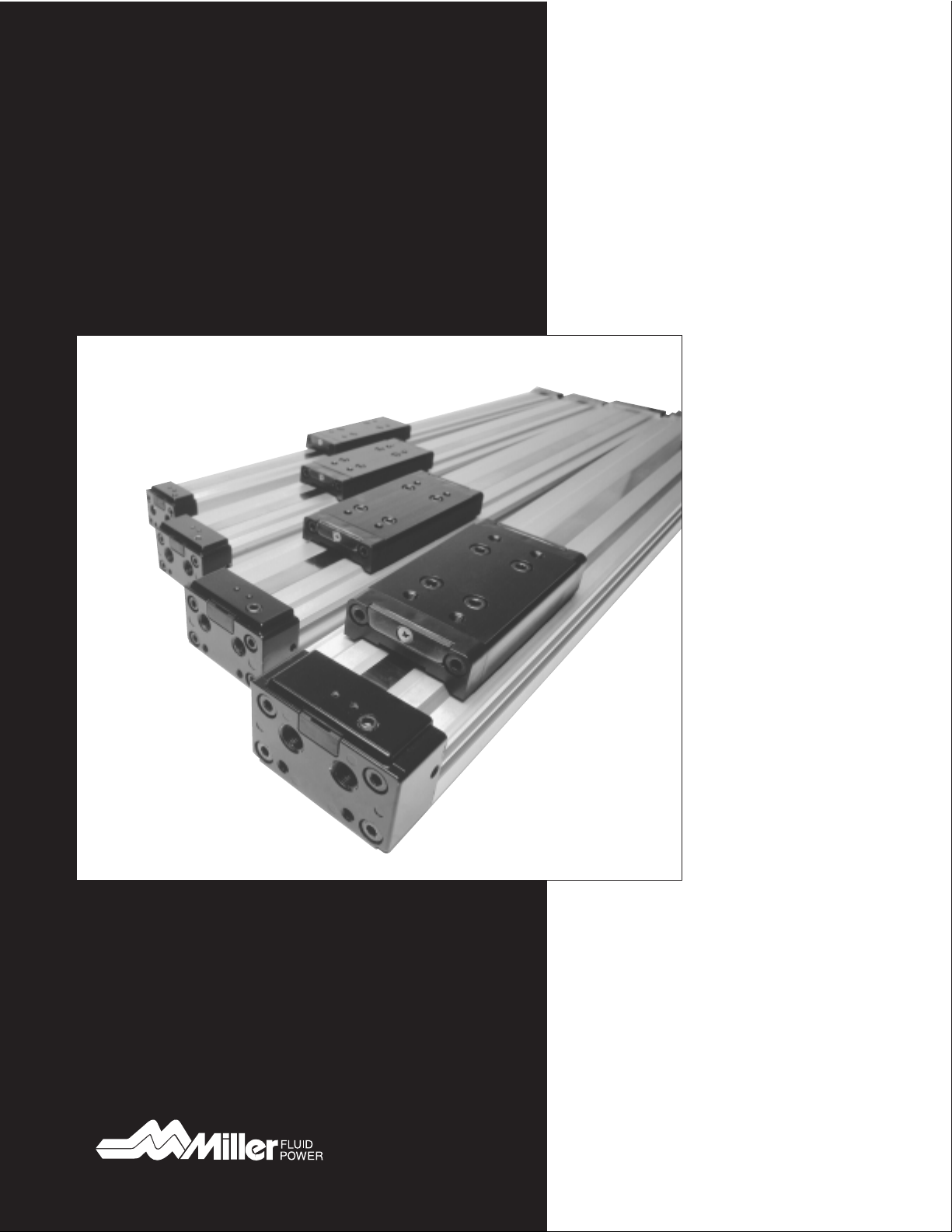
Miller SRL2-M Series
Rodless Cylinders
2
A Series Cylinders
Up to 250 PSI
Permanently lubricated
Series A steel air cylinders are available in bore
sizes from 1
1
⁄
2
"through 20"and up to 250 psi
operating pressure. Standard NFPA dimensions
and proven Miller design features. (File 7619)
AL Series Cylinders
Up to 200 PSI
Permanently lubricated
Our new aluminum AL Series air cylinders are
available in bore sizes from 1
1
⁄
2
"through 8".
Operating pressures up to 200 PSI. Dimensions
are NFPA Standard. (File 8564)
J Series Cylinders
500-2500 PSI
Our popularly-priced line of medium pressure
hydraulic cylinders, with bore sizes from
1
1
⁄
2
"to 20". (File 7620)
H Series Cylinders
3000-5000 PSI
Miller's heavy-duty cylinder line for the most
demanding hydraulic applications. Bore sizes
from 1
1
⁄
2
"to 20". Heavy-duty construction.
(File 7622)
Table Of Contents
Index and Warranty..................................................................................................... Page 2
Features and Benefits ....................................................................................................... 3-5
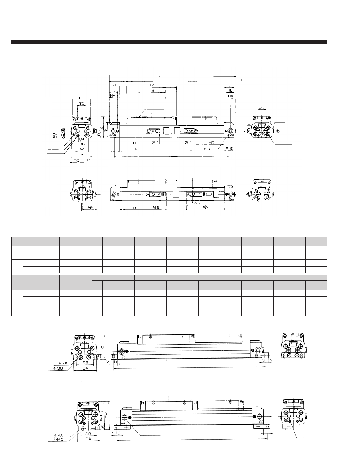
Dimensions....................................................................................................................... 6-7
Switches......................................................................................................................... 8-12
Switch Specifications and How to Order.............................................................................. 9
Switch Operating Range......................................................................................................10
Notes on Switch Usage..................................................................................................11-12
Cylinder Specifications and How To Order..........................................................................13
Accessories and Options ...............................................................................................14-15
Stroke Adjuster and Shock Absorber Dimensions...............................................................16
Technical Information....................................................................................................17-20
Rodless Cylinder Sizing Guide...................................................................................... 21-27
Sizing Forms................................................................................................................. 28-31
Air Consumption Chart....................................................................................................... 31
Plant Locations .................................................................................................................. 32
Miller's Rodless cylinders are warranted for one (1) year to be free from defects in
workmanship and material. Miller will replace, free of charge including lowest transportation
costs, but not including installation or any other charges, any part that Miller's inspection
shows to be defective. All defective parts must be returned to Miller's plant within warranty
period after shipment by Miller. Written permission for such return must first be obtained.
A complete explanation is required of the defects and circumstances. This warranty applies
only if goods fail to function properly under correct use, normal operating conditions, and
proper application because of defects in material or workmanship, and if Miller is notified
promptly in writing of such failure. If goods are in accordance with or in reference to an
engineering drawing specified by or furnished to the customer, these specifications and
information shall be applicable in determining such correct use, operation and application.
MILLER MAKES NO WARRANTY THAT THE GOODS ARE DELIVERED FREE OF THE
RIGHTFUL CLAIM OF ANY THIRD PERSON BY WAY OF INFRINGEMENT OR THE LIKE.
THERE ARE NO WARRANTIES OF MERCHANTABILITY OF FITNESS FOR A PARTICULAR
PURPOSE OR ORDINARY PURPOSE NOT WITHSTANDING ANY DISCLOSURE TO MILLER
OF THE USE TO WHICH THE PRODUCT IS TO BE PUT.
Miller shall never be liable for any consequential or incidental damages. The sale of Miller's
products under any other representation, warranty or guarantee, express or implied, is not
authorized by Miller.
Other Miller Air and Hydraulic
Cylinders.
Order Catalog by File No.
Miller One Year Warranty