Miller ArtX 3 User manual

Naked Fluid Head
OPERATOR’S MANUAL
1114 ArtX 3 Naked Fluid Head
1116
ArtX 5 Naked
Fluid Head
1118
ArtX 7
Naked Fluid Head

2
Features
Positive pan-tilt locks
calliper brake system
Tilt drag
selector
ring
Side-loading quick
release platform
Pan drag
selector
ring
Accessory mounting adaptor
points both sides
Counterbalance
selector ring
Illuminated
bubble level
Spare
camera
screws
Replaceable
serrated washer

3
Introduction
Congratulations, you are actually reading the operations manual!
So many people dismissed user guides these days, but a product
with any degree of complexity and sophistication, one with
robust and exible features such as the one you just bought, is
going to take a little bit of guring out. That’s what this manual
is for.
Register your warranty
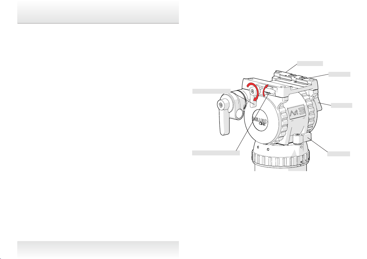
Product Overview
You are now the proud owner of a Miller Fluid Head known as
a “Naked Head” designed for maximum versatility for creative
artists. ArtX is a new concept that provides choices to enable
users to customise a uid head to t their exact purpose.
The key features of ArtX are:
• Customisable uid head
• Flat base (tripod mounting attachments optional)
• The Right Feel, smooth start, soft stop, uid drag
technology.
• Balanced diagonal transitions
• 15+0 CB PlusTM selectable counterbalance positions
• Ergonomically located CB Plus switch
• Positive selection radial drag ring controls
• Illuminated bubble level
• Precise oating pan-tilt calliper locks ensure bounce
free on-off performance
• Robust construction for rugged outdoor shooting
conditions
• Two side mounting points for viewnders and
accessories
• Wear-resistant serrated rosette washer
• Three years full warranty
• Designed and manufactured in Australia
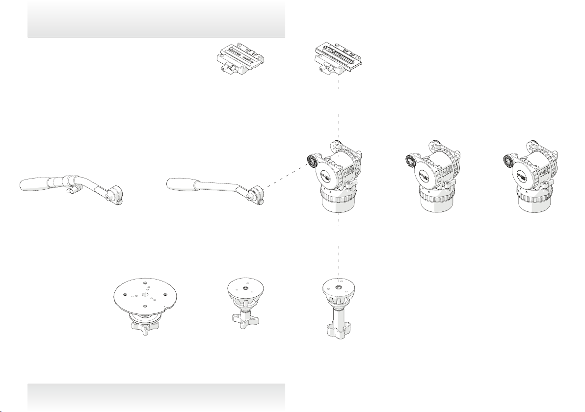
To ready the uid head for use the following are required
a) uid head
b) sliding platform
c) pan handle
d) tripod attachment ( unless used as athead)
Please refer to g 1.
Before we go any further is
very important that you go to
millertripods.com/en/warranty
and register your warranty to
claim your three full factory
warranty. Please read the
warranty information on the same
registration page on the website.
If it is not done now probably it
never will.

4
Naked Fluid Head Options
CAT. # 1276
MILLER BASE PLATE &
CAMERA PLATE
CAT. # 679
STANDARD PAN
HANDLE
CAT. # 694
TELESCOPIC PAN
HANDLE CAT. # 1116
ARTx 5 FLUID HEAD NAKED
CAT. # 1118
ARTx 7 FLUID HEAD NAKED
CAT. # 1288
DIA. 75mm CLAW
BALL
CAT. # 1290
DIA. 100mm CLAW
BALL
CAT. # 1225
MITCHELL BASE
OR
OR
OROR
OR OR
CAT. # 1278
VERSA BASE PLATE &
CAMERA PLATE
CAT. # 1114
ARTx 3 FLUID HEAD NAKED
Fig. 1

5
Use this manual to familiarise yourself with the operation of
the ArtX Fluid Head and observe these instructions to prevent
any damage to your equipment. Ensure that all equipment is
operating correctly and free from defects and damage, also
ensure that the tripod is steady, secure and that the bowl is
approximately horizontal when attaching the camera. The
operator is responsible for the safe operation of this piece of
equipment.
Safety Instructions
Slide Lock Lever
Pan Lock
Tilt Lock
Platform
Safety Release Lever
Cat# 1278
• Do not exceed the maximum payload capacity of the
Fluid Head
• Do not leave the camera unattended on the Fluid Head
• Do not release the SLIDE LOCK LEVER whilst the
camera is at an angle.
• Do not adjust the tripod whilst the camera is attached
to the Fluid Head.
• Ensure PAN HANDLE CLAMP and CLAMP NUT is
securely tightened.
• Apply TILT LOCK when adding/removing equipment
from the camera or when attaching/removing the
camera from the Fluid Head.
• Hold camera securely whilst changing Counterbalance,
Pan Drag or Tilt Drag settings.
• Hold the camera securely whilst releasing the SAFETY
RELEASE LEVER.
• Hold camera securely whilst adjusting the CLAMP NUT
to level the Fluid Head.

6
Assembly
Fig. 3
2 x 1/4” Thread
50.0
3 x M5 Thread
3/8” Thread
Baseplate
Attach the Base Plate Assembly (Cat #1278 or #1276) using the
supplied M5 x 16 Socket Cap Screws (4) and a 4mm Hex key.
Lightly tighten the rst screw and then the remaining 3 screws
by working in a cross pattern. Re-tighten rmly all screws.
After tightening all screws, assemble the camera plate and check
that the camera plate is securely captured and slides smoothly,
then apply SLIDE LOCK LEVER and check holding force. Release
the SLIDE LOCK SCREW and the SAFETY RELEASE LEVER and
remove the camera plate.
Fig. 2
Flat Base Adaptors
All adaptors must be assembled using the supplied M5 x 12
Socket Cap Screws and a 4 mm Hex key.
Tighten securely and do not use alternative length screws.

7
Fig. 4
Assembly
To Suit
75mm Bowl
To Suit
100mm Bowl
Fig. 5

8
2.Mounting Your Camera
2.1 Remove the CAMERA PLATE by lifting the SAFETY
RELEASE LEVER on the PLATFORM (SLIDE LOCK LEVER
must be unwound (clockwise)) (Fig. 6a).
2.2 Attach the CAMERA PLATE to the camera
1
such that
the Centre of Gravity (C of G)
2
mark on the camera is
approximately in the middle of the camera plate.
2.3 Tighten PAN/TILT LOCKS, mount the CAMERA PLATE
to the PLATFORM non-locking side rst. The side load
lock mechanism will capture camera plate (distinct click
sound will be made when CAMERA PLATE is retained).
CAMERA PLATE will be able to slide freely until SLIDE
LOCK LEVER is tightened.
2.4 Release TILT LOCK, slide the CAMERA PLATE such that
the camera’s C of G is directly above the centre axis of
the Fluid Head (g. 6b), camera should be balanced (if
not slide camera backward or forward). Once balanced
tighten the SLIDE LOCK LEVER (anti-clockwise)
3
and
tighten TILT LOCK.
If this cannot be achieved then reposition the CAMERA
PLATE on the Camera – step 2.2.
NOTES:
1
Refer to the camera’s owners manual for correct method of
attachment to the CAMERA PLATE. Remove the 1/4” screw
or 3/8” screw or 1/4” Pin (#1201 Camera Plate only) as
required.
2
The camera’s C of G can be estimated by placing the
camera on to a round rod and then shifting it backwards
or forwards until a balance point – C of G - is achieved. It is
recommended to identify this point on the camera as it will
be useful in step 2.2.
3
Ensure SLIDE LOCK LEVER is tightened at all times when
you are not nding C of G or mounting/dismounting camera.
Operating Instructions
Fig. 6b
Fig. 6a
Centre Axis
Slide Lock Lever
Pan Lock
Tilt Lock
Platform
Safety Release Lever
C of G
Cat# 1278

9
Fig. 6a
Pan Lock
Tilt Lock
Platform 3.Counterbalance Control
The counterbalance system was designed to neutralise the
effect of the camera weight when it is tilted. The ArtX Fluid
Head offers a 15 position counterbalance system which is
operated with the CB SELECTOR RING and the CB PLUS
SELECTOR (Fig. 7). With ArtX it is also possible to disengage
counterbalance (position zero),
NOTE:
Be careful when disengaging counterbalance as you could
damage your equipment with an unwanted tilt drop.
The CB SELECTOR RING and the CB PLUS SELECTOR must
be operated when the BASE PLATE is in a horizontal position.
After changing the counterbalance setting it may be
necessary to tilt the camera back and forth to ensure that the
CB spring has engaged.
3.1 For safety it is generally better to start at a higher
counterbalance position (e.g. position 14) and work your
way to the correct setting, this is to reduce any chance of
unwanted tilt drops (Fig. 7).
3.2 Hold the camera and release the TILT LOCK, then gently
tilt the camera from the horizontal position forward
then backward and observe its response. If the camera
‘springs back’ to the horizontal position then a lower
counterbalance setting is required, use the CB SELECTOR
RING to cycle through all even number positions (eight
positions including zero).
3.3 Finer adjustments can be made by engaging the CB PLUS
SELECTOR (upward direction).
3.4 Correct counterbalance setting has been achieved when
the camera does not spring back or drop when pan
handle is released.
Operating Instructions
Fig. 7
CB PLUS on
CB PLUS off
CB PLUS Selector
CB Selector Ring
Cat# 1278

10
Operating Instructions
4.Pan/Tilt Drag Control
The ArtX
Fluid Head offers selectable positions of uid drag
in the Pan and Tilt (including zero positions). The settings are
equally stepped from lighter drag in position 1 up to heavier
drag in position 3 on ArtX 3 and ArtX 5 models and position
5 on ArtX 7, the drag plates are completely disengaged in
position zero.
• Do not pan or tilt the Fluid Head whilst adjusting PAN or
TILT DRAG CONTROL or whilst the PAN and TILT DRAG
CONTROL is between settings.
• The drag setting can be changed at any tilt or pan angle.
5.Pan/Tilt Lock Control
The ArtX Fluid Head offers high capacity caliper disc brake
system to hold the Fluid Head in a xed pan and/or tilt
position. Camera position will not change when applying or
releasing the Pan-tilt locks.
• Do not pan or tilt the Fluid Head whilst the PAN or the TILT
LOCK is partially applied.
6.Illumination
The
ArtX
Fluid Head offers illumination of the BUBBLE LEVEL
when the low ambient light conditions exist. Illumination
can be achieved by pressing the LED BUTTON once. The
light will switch off after 10 seconds.
Fig. 8

11
The ArtX Fluid Head offers high quality surface coatings, dust and
moisture seals. Miller recommends keeping the Fluid Head clean at all
times by using soft brushes and lint free cloth to wipe over the sur-
faces.
• Do not immerse the Fluid Head in any liquid.
• Do not use stiff brushes, abrasives, harsh detergents and solvents.
Battery Replacement
T
he
ArtX
Fluid Head uses a single 11A type - 6 Volt battery for Illumi-
nation. Miller recommends the following batteries to provide long life
performance – GP11A, Duracell MN11 or Vinnic L1016.
1. Using a Phillips Head #1 screw driver, remove the RETAINING
SCREW and the BATTERY COVER.
2. Using a small at screw driver remove the battery.
3. Align the new battery as shown on the back of the BATTERY
DOOR and place into the BATTERY HOUSING, then push down
the battery into place. A small at screw driver may be used to
push down the battery into the BATTERY HOUSING.
4. Align the BATTERY DOOR into the body then tighten the screw
lightly.
Storage
The ArtX Fluid Head can be stored for extended periods; Miller
recommends storage in a Miller case and the following:
• Clean the external surfaces.
• Keep in a dry place away from direct sunlight.
• Loosen off PAN & TILT LOCK.
Maintenance
Fig. 9
Battery
Battery Cover

12
Options & Accessories
CAT# Product Name
3940 Versa Kit - 75mm claw ball, 679 pan handle, and Versa base plate
3942 Miller Kit - 75mm claw ball, 679 pan handle, and Miller base plate
3943 Versa Kit - 100mm clawball, 679 pan handle, and Versa base plate
3944 Miller Kit - 100mm claw ball, 679 pan handle, and Miller base plate.
679 Pan Handle - Fixed - with Black Handle Carrier to suit ArtX
696 Pan Handle - Telescopic - with Black Handle Carrier to suit ArtX
1276 Miller Camera Platform Side Load (CX Miller) to suit CompassX, ArtX Fluid
Heads (comes with Miller 1205 camera plate)
1278 Versa Camera Platform Side Load to suit CompassX, ArtX Fluid Heads
(comes with Versa 1201 camera plate)
1201 Versa Camera Plate Ass’y (to suit 1278 Versa base plate)
1205 Standard Camera Plate (60mm sliding range) including 1/4” & 3/8” screws
to suit ArtX 1276 Platform
1236 Serr. Handle Clamp Extension (D36 Arri) (CX ArtX) to suit CompassX, ArtX
Fluid Heads
1238 Serr. Handle Clamp Extension (Miller) (CX ArtX) to suit CompassX, ArtX
Fluid Heads
1248 D15 Sleeve adaptor to suit D15 small rig rods
1222 Arri Mounting Adaptor (CX ArtX) to suit CompassX and ArtX Fluid Heads
1255 Accessory Mounting Block Kit (CX ArtX) to suit CompassX and ArtX Fluid
Heads
1270 Accessory Mounting Block Arri Kit (CX) to suit CompassX and ArtX Fluid
Heads
1288 D75 Claw Ball Level to suit ArrowFX, CiNX and ArtX Fluid Heads
1290 D100 Claw Ball Level to suit ArrowFX, CiNX and ArtX Fluid Heads
PN14222 1/4” Camera Screw (long) to suit Versa 1201 Camera Plate
PN14223 3/8” Camera Screw (long) to suit Versa 1201 Camera Plate
PN14224 3/8” Screw to 1/4” Pin (#1201 Camera Plate only)
Service, Sales and Support
Miller Authorised Service Agents must carry out all service
and repair work. Failure to observe this requirement may void
warranty.
It is advisable to notify Miller or a Miller Authorised Service Agent
if a change of performance is observed as a result of dropping
or rough usage. For information regarding sales and service of
Miller products or for your nearest Miller representative please
contact us via our website or at the following:
MILLER CAMERA SUPPORT EQUIPMENT
6 Ross Place
Wetherill Park, Sydney, NSW 2164 Australia
P +61 2 9439 6377
sales@miller.com.au
MILLER Camera Support (LLC) USA
216 Little Falls Road (Unit 2),
Cedar Grove, New Jersey 07009 USA
P +1 (973) 857 8300
F +1 (973) 857 8188
MILLER FLUID HEADS (EUROPE) LTD.
12A, Shepperton Business Park
Govett Avenue, Shepperton
Middlesex, TW17 8BA
United Kingdom
P +44 (0) 1932 222 888
millertripods.com

13
1114 A r t X
3
1116 ArtX 5 1118 A r t X
7
Weight (naked head
only)
2.2kg (4.8lbs) 2.2kg (4.8lbs) 2.4kg (5.28lbs)
Payload range 0-8kg (0-17.5lbs) 0-10kg (0-22.0lbs) 0-14kg (0-30.8lbs)
Pan-tilt drag 3 selectable uid drag positions + 0 3 selectable uid drag positions + 0 5 selectable uid drag positions + 0
Drag max. torque 3.5 Nm 3.5 Nm 9 Nm
Pan range 360°
Pan-tilt locks Positive lock caliper
brake system
Tilt angle +90˚/-75˚
Counterbalance 16 selectable positions
(0 +15 position)
Camera Platform Quick Release Side Load
Sliding Range 60 mm (2.5”) - # 1205 (Miller)
105 mm (4.1”) - # 1201 (Versa)
Height above bowl 202 mm (7.9”) – on Ball Level Adaptor
197 mm (7.8”) – on Mitchell Base Adaptor
Mounting base Centre 3/8”, 2 x ¼” and 3 x M5 threads
for at base or ball levelling adaptor mounting
Illuminated controls Bubble Level
Temperature range -40° to +65°C
(-40° to +149°F)
Pan Handle LH & RH Side Mount
Specications

14
Mechanical Specications
0
2
4
6
8
10
12
14
123456
7
Torque (Newton Metres)
Drag Position
Drag Torque
0
2
4
6
8
10
12
14
123456
7
Torque (Newton Metres)
Drag Position
Drag Torque
0
2
4
6
8
10
12
14
1234567
Torque (Newton Metres)
Drag Position
Drag Torque
162.5 (6.4”)
106.5 (4.2”)
140.0 (5.5”)
Height
Above
Bowl
75 (2.95”)
162.5 (6.4”)
106.5 (4.2”) 140.0 (5.5”)
Height
Above
Bowl
100 (3.95”)
213.9 (8.4”)
68.9 (2.7”)
193.2 (7.6”)
211.9 (8.3”)
68.9 (2.7”)
193.9 (7.6”)
162.5 (6.4”)
106.5 (4.2”)
140.0 (5.5”)
Height
Above
Bowl
75 (2.95”)
162.5 (6.4”)
106.5 (4.2”) 140.0 (5.5”)
Height
Above
Bowl
100 (3.95”)
213.9 (8.4”)
68.9 (2.7”)
193.2 (7.6”)
211.9 (8.3”)
68.9 (2.7”)
193.9 (7.6”)
162.5 (6.4”)
106.5 (4.2”) 140.0 (5.5”)
Height
Above
Bowl
75 (2.95”)
162.5 (6.4”)
106.5 (4.2”)
140.0 (5.5”)
Height
Above
Bowl
100 (3.95”)
213.9 (8.4”)
68.9 (2.7”)
193.2 (7.6”)
211.9 (8.3”)
68.9 (2.7”)
193.9 (7.6”)
162.5 (6.4”)
106.5 (4.2”) 140.0 (5.5”)
Height
Above
Bowl
75 (2.95”)
162.5 (6.4”)
106.5 (4.2”)
140.0 (5.5”)
Height
Above
Bowl
100 (3.95”)
213.9 (8.4”)
68.9 (2.7”)
193.2 (7.6”)
211.9 (8.3”)
68.9 (2.7”)
193.9 (7.6”)
0 5 10 15 20
75
100
125
150
175
Camera Payload (kg)
Above camera plate (mm)
Payload Range (ArtX 3)
0 5 10 15 20
75
100
125
150
175
Camera Payload (kg)
Above camera plate (mm)
Payload Range (ArtX 5)
0 5 10 15 20
75
100
125
150
175
Camera Payload (kg)
Above camera plate (mm)
Payload Range (ArtX 7)

15
Compatible Tripods
420 Toggle 75 2-stage (alloy) 420G Toggle 75 2-stage (alloy) 440 Toggle 75 LW tripod (alloy) 440G Toggle 75 LW tripod (alloy) 402 Toggle 100 2-stage (alloy) 402G Toggle 100 2-stage (alloy)
2500 Solo-Q 75 2-stage (CF) 2505 Solo-Q 75 3-stage (CF) 2515 Solo-Q 100 2-stage (CF) 2520 Solo-Q 100 3-stage (CF)
1576 Sprinter II 100 2-stage (CF)
1620 Sprinter II 75 2-stage (CF) 1620G Sprinter II 75 2-stage (CF)
1589 Sprinter II 100 1-stage (CF) 1589G Sprinter II 100 1-stage (CF) 1580 Sprinter II 100 2-stage (CF) 1580G Sprinter II 100 2-stage (alloy) 1576G Sprinter II 100 2-stage (alloy)

millertripods.com
MILLER CAMERA SUPPORT EQUIPMENT
6 Ross Place
Wetherill Park, Sydney
NSW, 2164, Australia
Tel: +61 2 9439 6377
Email: sales@miller.com.au
D14458-1
This manual suits for next models
5
Table of contents
Other Miller Industrial Equipment manuals