milleteknik NEO 24V 15A-25A FLX L PRO1 User manual

NEO 24V 15A-25A FLX L PRO1
EN

350-143
Publication date 2023-04-12

Table of Contents
1. About NEO ................................................................................................................................ 3
2. Steps for installation and deployment .......................................................................................... 4
3. Mounting FLX L ......................................................................................................................... 4
4. Component overviews ................................................................................................................ 6
4.1. Component overview NEO FLX L ..................................................................................... 6
5. Batteries - placement and connection .......................................................................................... 7
5.1. Placement of batteries ..................................................................................................... 7
5.2. Connecting batteries in FLX M ......................................................................................... 8
5.3. Connection of batteries in FLX S, FLX M and FLX L .......................................................... 8
6. Motherboard - description ........................................................................................................... 9
6.1. Fuses ........................................................................................................................... 10
6.2. Connect the mains to the motherboard (PCB) ................................................................. 11
6.2.1. Connect mains ................................................................................................... 11
6.3. Connect load ................................................................................................................ 11
6.4. Connection of load 15 A - 25 A units ............................................................................... 12
6.5. Dip-switch - S1 .............................................................................................................. 12
6.6. Reboot to confirm changes in address, battery and alarm settings to parent system .......... 13
6.7. Dip-switch - S1 .............................................................................................................. 13
6.8. Note on Dip switch 3 ...................................................................................................... 13
6.9. Fan speed - setting, Dip-switch 5 .................................................................................... 13
6.10. Battery capacity setting, Dip switch 5-7 ......................................................................... 14
6.11. Resetting data after battery change (Dip-switch 8) ......................................................... 14
7. Connection of PRO 1 with alarm card in NEO ............................................................................ 15
7.1. Connect load (PRO1) ................................................................................................ 15
7.2. Alarm card for PRO1 ..................................................................................................... 15
7.3. Alarm displayed on cabinet door ..................................................................................... 16
8. Commissioning - how to start the unit ........................................................................................ 16
9. Circuit boards - Technical data .................................................................................................. 17
9.1. Technical data, motherboard: PRO 1 .............................................................................. 17
9.1.1. Alarm ................................................................................................................. 17
10. Power supply ......................................................................................................................... 18
10.1. Power supply - Technical Data RSP-320-24 .................................................................. 18
10.2. Power supply - Technical Data HRP-600-24 .................................................................. 19
11. Technical data enclosures ....................................................................................................... 19
11.1. Enclosures - Technical Data FLX L ............................................................................... 19
12. Batteries - recommended, not included .................................................................................... 20
12.1. Batteries are not included they are sold separately ........................................................ 20
12.2. 45 Ah, 12 V AGM battery ............................................................................................. 20
12.3. Reserve operating times for different alarm classes - overview ....................................... 20
13. Regulations and certifications ................................................................................................. 22
13.1. Requirements that the product meets ........................................................................... 22
14. Address and contact details .................................................................................................... 22
1. ABOUT NEO
NEO is normally used in security systems where the requirements are higher for more functions, alarm
functions, longer backup operating times or when the battery backup is to handle higher loads.
3

2. STEPS FOR INSTALLATION AND DEPLOYMENT
The unit must be installed and deployed in the following order:
1. Installation of the device.
2. Connecting batteries.
3. Connection of load.
4. Connection of communication or to external alarm. If communication / external alarm is not required
or if the device cannot communicate - skip this step.
5. Mains connection.
6. Commissioning
CAUTION
When the mains is connected, the unit is put into operation. Therefore connect the
electrical network (mains) last to avoid faults on other equipment that is connected
on load or over communication. The unit also does not register batteries if they are
connected after the mains has been connected.
3. MOUNTING FLX L
The unit can be mounted in a 19" rack or on a wall. The supplied brackets can be attached in two ways:
When mounting on a wall, the brackets must sit backwards, against the wall. When mounting in a 19"
rack, the console must sit at the front of the unit.
4
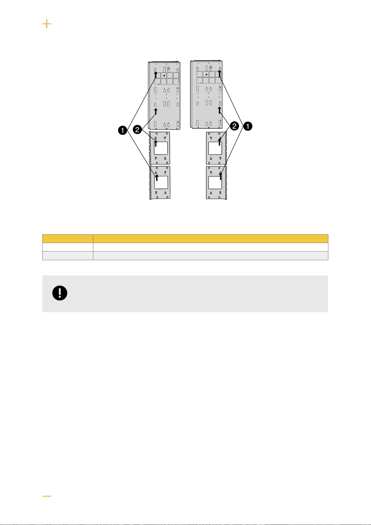
Figure 1. FLX L - mount brackets
Left bracket facing the front for mounting in a 19 "rack.
Right bracket facing the back for wall mounting.
Nr Explanation
1 Start by attaching the top bracket.
2 Attach the lower bracket.
IMPORTANT
Leave 100 mm free around the air vents.
5

4. COMPONENT OVERVIEWS
4.1. Component overview NEO FLX L
Table 1. Component overview
Letter Explanation
A Console, reversible for mounting in a wall or 19" rack.
B Optional: Tamper switch
C Cabinet in powder-coated sheet metal.
D Space for optional cards
E Power supply, located on the back in some configurations.
F Cable entries.
G Motherboard.
H Lockable door.
I Space for batteries.
6

5. BATTERIES - PLACEMENT AND CONNECTION
5.1. Placement of batteries
No Explanation
1 Slide the battery behind the tamper switch into the battery backup (I).
2 Slide the battery into the battery backup (I).
No Explanation
1 Slide the first battery. If there is a tamper connector here, the battery must be pushed in behind the tamper connector.
2 Slide in the second battery.
7

5.2. Connecting batteries in FLX M
Figure 2. Connection of batteries in FLX M. Motherboards may differ depending on the configuration, but connection of batteries takes
place in the same way.
Note that cards (4) differ from different configurations.
No Explanation
1 Minus coil for battery cable from 4.
2 Fuse.
3 Plus terminal for battery cable from 4.
4 Motherboard, varies with configuration.
5 Battery cables are located on the system board.
6 Connection for connection of battery box.
5.3. Connection of batteries in FLX S, FLX M and FLX L
Battery wiring is mounted on the circuit board upon delivery. Pictures below only show how to connect
wiring.
1. Place the batteries in the cabinet with the battery terminals facing outwards.
2. Connect the battery cable. Red cable on + and black cable on -.
• If possible, disconnect mains voltage when replacing the battery.
8

Figure 3. Wiring diagram for batteries in battery backup
Connect the terminals correctly so that you do not damage the equipment.
6. MOTHERBOARD - DESCRIPTION
Motherboard controls the device, distributes power and communicates with other systems. See techni-
cal data for more information.
Figure 4. PRO1
Table 2. Circuit board overview, explanation
No . On circuit board Explanation
1 PGM1 Port for firmware update.
2 J12 Connection indicator diode.
3 J5 Termination by jumper, (at over 120 Ω, RS-485).
4 J9 Effect card connection.
9
No . On circuit board Explanation
5 P2:5-13 Connection for communication.
6 F3 Fuse, load 2 +. (5A and 10A units.)
7 P2:1-4 Load outputs for 5 A and 10 A units only.
8 F2 Fuse, load 1 -. (5A and 10A units.)
9 F1 Fuse, load 1+. (5A and 10A units.)
10 J2 Connection to fan.
11 J11 Tamper switch connection.
12 J7 Connection tamper switch from battery box.
13 JU2 Input from external fuse card, NO.
14 J15 Input from external fuse card, NC.
15 J13 Connection to external alarm. Optional card.
16 F6 See fuses.
17 P1:1-3 Incoming mains, (230 V). Line, Phase, PE.
18 J16 Power resistor connection.
19 J4 Power resistor connection.
20 D-sub Connection option card via D-sub.
21 F4 Battery fuse.
22 J8 Connection to relay/communication card.
23 S1 Dip switch 1-8
6.1. Fuses
Fuses Type Explanation
F1 See table: fuses Fuse, load 1 plus +.
F2 Fuse, load 1 minus -.
F3 Fuse, load 2 plus +.
F4 Battery fuse.
F6 Mains fuse.
FUSE REPLACEMENT WARNING (A)
There is a risk of damage if the fuse is changed to a larger one than what the unit
is delivered with. The function of the fuse is to protect the connected load and cables
against damage and fire. It is not possible to change the fuse to a larger one to
increase the power output.
Table 3. Fuses
Fuse Type
15 A T15A
25 A T25A
Mains fuse for 24 V units up to 15 A T2.5AH250V. Ceramic.
Mains fuse for 24 v units over to 15 A T4AH250V. Ceramic.
10

6.2. Connect the mains to the motherboard (PCB)
6.2.1. Connect mains
Pull wiring through the cable entry on the cabinet.
If possible, secure the mains cable with cable ties where possible.
Electrical network cabling shall be kept separate from other cabling to avoid EMC interference.
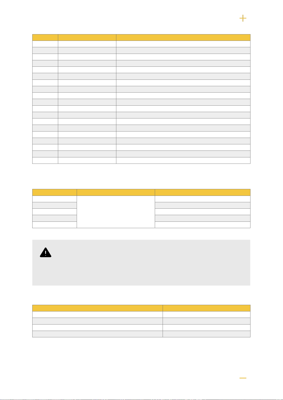
Figure 5. Connect the mains to the motherboard
Connect the mains cable to the terminal before it is put back on the motherboard. Secure F and N with
cable ties for electrical safety.
Table 4. Electrical network connections
Letter Explanation
F Phase
N Neutral
PE Protective earth
ELECTRICAL MAINS CONNECTION 230 V AC ON CIRCUIT
BOARD
Check that the marking on the circuit board matches the cable arrangement on the
terminal block.
6.3. Connect load
MAX CURRENT
Maximum current must not be exceeded. Maximum current is indicated on the CE-
marking on the unit.
If there are one or more connection cards (to increase the number of load outputs), load must be
connected there and not on the main board.
Table 5. Load connections
Circuit board number Explanation
P2: 1 Connection for load 1 +
P2: 2 Connection for load 1 -
11

Circuit board number Explanation
P2: 3 Connection for load 2 -
P2: 4 Connection for load 2 +
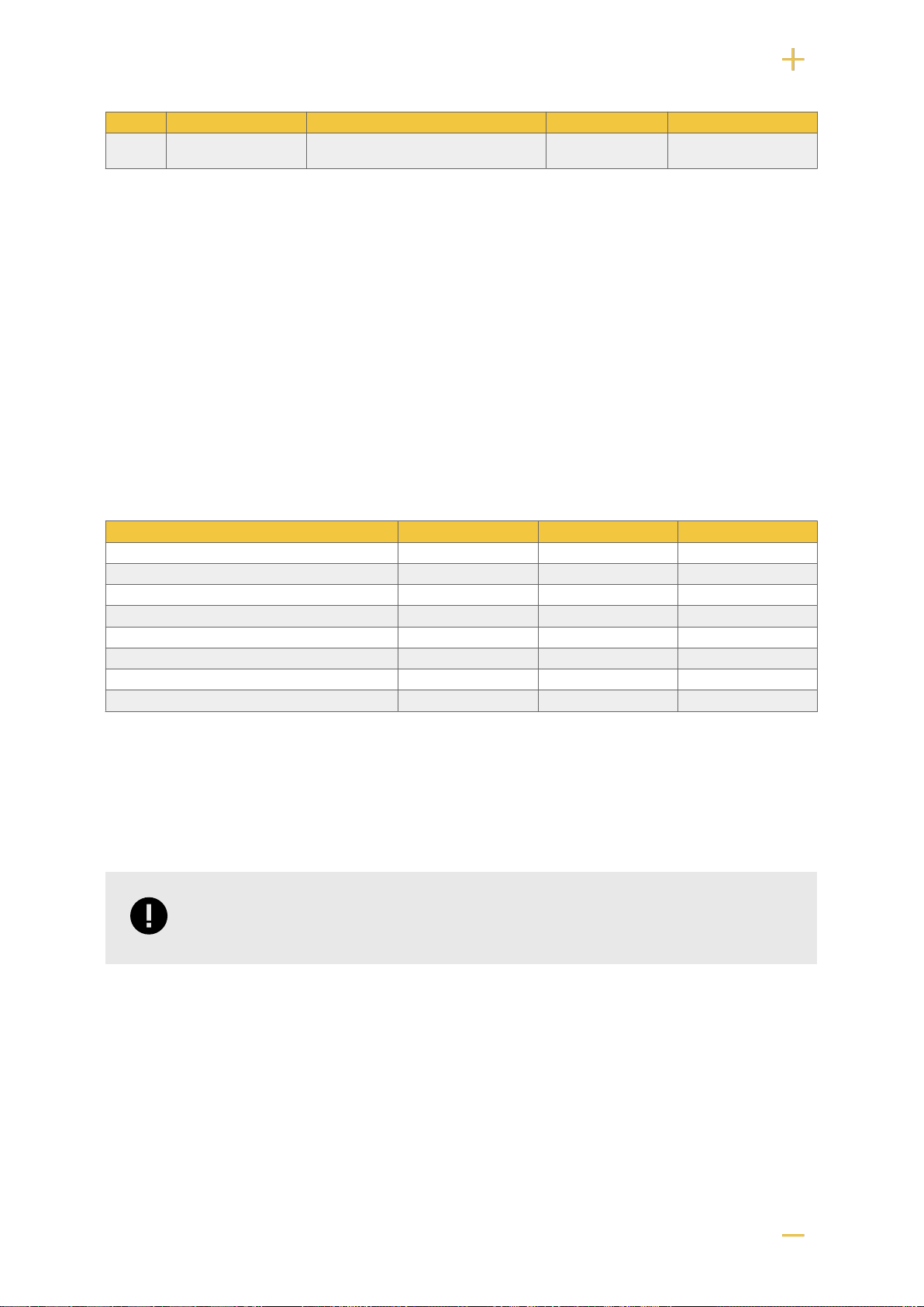
6.4. Connection of load 15 A - 25 A units
For units with a effect card, which is available to handle the higher currents (15 ampere and above), the
load must be connected on an optional board.
See documentation for option board for how to connect load.
WARNING
Load must not be connected to the motherboard if the device is a 15 A or 25 A, as it
will be destroyed during commissioning. Motherboards that are faulty due to incorrect
connections are not covered by warranty.
Figure 6. Effect card
The effect card increases the current for 15 A and 25 A units.
6.5. Dip-switch - S1
The contact on the dip switch has two positions, ON and OFF.
Dip-switch S1 Explanation
1-4 For address setting to external communication.
1-2 Sets time delay for mains failure alarm. (I2C)
3-4 Not used.
5 Sets the fan speed.
5-7 Battery capacity setting.
8 For software reset.
12

NOTE
NEO cannot be connected to communication/UC.
6.6. Reboot to confirm changes in address, battery and alarm set-
tings to parent system
After the dip-switch has been set for various parameters, the device's software needs to be restarted.
This is for the new settings to be stored and take effect.
Restarting the device software is done by turning Dip-switch 8: OFF-ON-OFF (PRO1)
IMPORTANT
Reboot must be done every time a change is made to the device.
NEO cannot be connected to communication/UC.
6.7. Dip-switch - S1
The alarm can be set in time intervals of 0 seconds, 15 minutes, one hour or four hours.
Time Dip 1 Dip 2
0 seconds OFF OFF
15 minutes ON OFF
60 minutes OFF ON
240 minutes ON ON
6.8. Note on Dip switch 3
In previous versions of the motherboard, it was possible to use Dip-switch 3 to control whether the unit
should alarm for fan failure or not.
This feature has been removed. Alarms for fan faults are given over communication.
6.9. Fan speed - setting, Dip-switch 5
Dip-Switch 5 sets the fan speed. (As of software V 4.27.)
Table 6. Fan speed - dip 5
Dip-5 Mode Temperature limit Benifit Drawback
OFF Normal mode (facto-
ry setting). High speed above 30°C, restores nor-
mal mode when the temperature is
25°C.
Best for battery
life. Louder noise from the
fan.
13
Dip-5 Mode Temperature limit Benifit Drawback
ON Office environment
mode. High speed at 35°C, restores normal
mode when the temperature is 30°C. Lower noise lev-
el. Shortens the lifespan
of the batteries.
6.10. Battery capacity setting, Dip switch 5-7
The device is set for the battery capacity that the product can handle the most (largest batteries). If
other batteries are to be installed, the battery capacity setting needs to be changed so that alarms and
functions works as intended.
• Setting the new battery capacity is done by keeping the tamper switch pressed while Dip-switch 5-7 is
changed and the unit is commissioned.
1. Open the device and let it operate normally.
2. Press the tamper switch on the door frame. The device is now in write mode for battery capacity
setting.
3. Set the connected battery capacity on the Dip switch, according to the table.
4. Release the tamper switch in the door frame. Battery capacity is now stored.
Table 7. Matrix for setting battery capacity
Batteries Dip 5 Dip 6 Dip 7
7,2 Ah OFF OFF OFF
14 Ah ON OFF OFF
20 Ah OFF ON OFF
28 Ah ON ON OFF
45 Ah OFF OFF ON
60 Ah ON OFF ON
90 Ah OFF ON ON
120 Ah and above ON ON ON
6.11. Resetting data after battery change (Dip-switch 8)
In order for the system to measure the capacity of new batteries, the unit needs to clean up previous
battery capacity. Dip-switch 8 makes a software set that, among other things, resets alarms.
IMPORTANT
The action clears the memory on the card immediately.
• Dip-switch 8 must be switched to: OFF-ON-OFF
14
7. CONNECTION OF PRO 1 WITH ALARM CARD IN NEO
7.1. Connect load (PRO1)
Load is connected to circuit breaker and not to circuit board - see component overview.
To cope with increased power, power is supplied via power cards to circuit breakers. Therefore, loads
must be connected to circuit breakers.
CAUTION
Maximum current must not be exceeded, see plate on the unit.
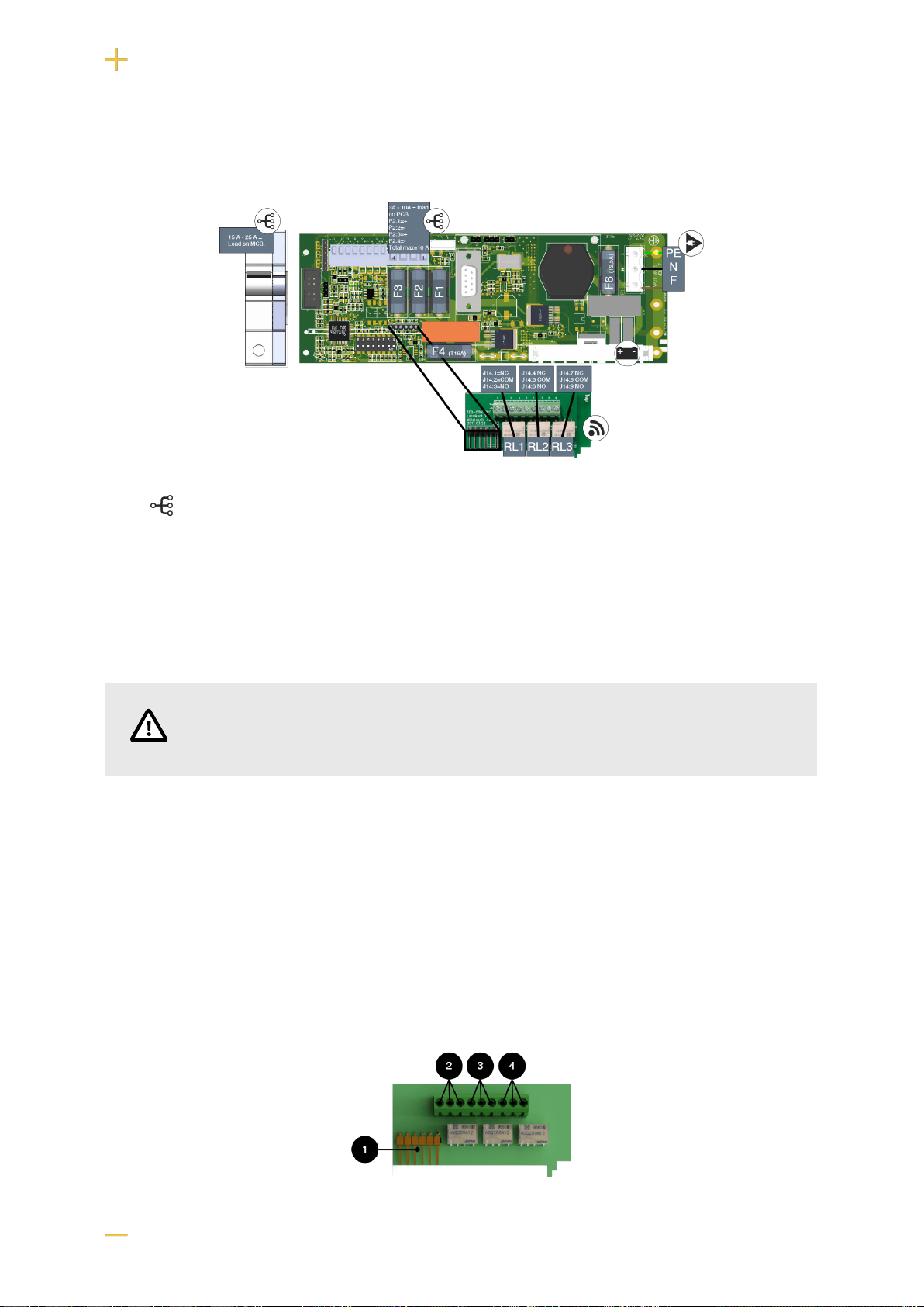
7.2. Alarm card for PRO1
Relay card - description, connections and alarm outputs.
• All fault alarm relays must be in the drawn state. Make sure the connection between CO and NC is at
closure. Put the measuring instrument on continuity measurement and test closure. This should then
indicate a short circuit.
• All relay outputs are normally live and give an alarm in the event of no voltage.
15
No . Relay (Terminal no.) The relay is normally energized. Alarm type or explanation
1 J12 - Connection to motherboard.
2 J14:1-3 NC, COM, NC Power outage alarm.
3 J14:4-6 NC, COM, NO Alarm for: Fuse failure, tamper switch*, charger fail-
ure overvoltage, charger failure undervoltage, cell fail-
ure/battery not connected, low battery voltage in case
of mains failure and aged battery*.
4 J14:7-9 NO, COM, NC Alarm for: Low system voltage.
Via communication on PRO1 card: All alarms and alarms for: Fan fault, overtemperature, subtemperature, short battery life left,
overcurrent 100% of minute average, overcurrent 80% daily average and overcurrent 175% second average.
* Optional on units that are not certified.
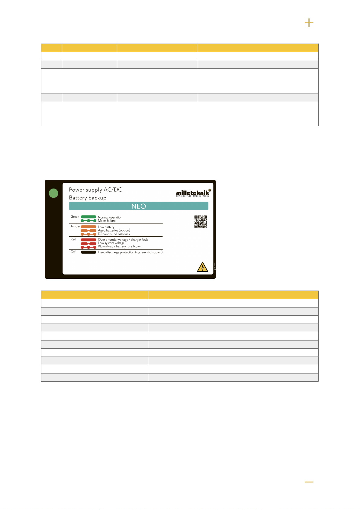
7.3. Alarm displayed on cabinet door
In normal mode, the indicator LED shows a solid green light.
The indicator diode (LED) shows Explanation
Solid green light Normal operation.
Slow green flashes Not available for NEO.
Fast green flashes Mains failure.
Solid yellow light Low battery voltage.
Slow yellow flashes Aged batteries, (option).
Rapid yellow flashes Disconnected batteries / battery cell shortage.
Solid red light Overvoltage or undervoltage or charger fault.
Slow red flashes Low system voltage.
Rapid red flashes Blown load / battery fuse has blown.
No light / off Deep discharge protection is activated. (System shutdown).
When operating system: If the indicator LED is off, deep discharge protection has come into force.
8. COMMISSIONING - HOW TO START THE UNIT
1. Connect batteries
2. Connect / switch on fuses
3. connect load, alarm and possibly. other connections.
16

4. Screw the mains cable into the terminal block and attach the terminal block to the motherboard.
5. Switch on mains voltage.
The unit works normally when the indicator LED on the outside of the cabinet door lights up with a solid
green light. See front panel for other status indications.
It may take up to 72 hours before the batteries are fully charged.
9. CIRCUIT BOARDS - TECHNICAL DATA
9.1. Technical data, motherboard: PRO 1
Info Explanation
Short name: PRO 1
Product description Main PCB in battery backup with advanced functions and communication to parent system.
Own consumption, with relay
card Less than 210 mA. 100 mA without power stage with all relays retracted on external alarm
card in normal mode.
Switching time from mains volt-
age to battery operation When batteries are idle: <5 microseconds. When batteries are in charge cycle: 0 (none). Bat-
teries rest for 20-day cycles, after which a charging cycle picks up and charges the batteries
for 72 hours. If there is a power failure when batteries are in the charge cycle, there is no
switching time.
Incoming electricity network 230 V AC -240 V AC, 47-63 Hz.
Fuse on mains See table: Fuses.
Indication Indicator diode on circuit board / cabinet door
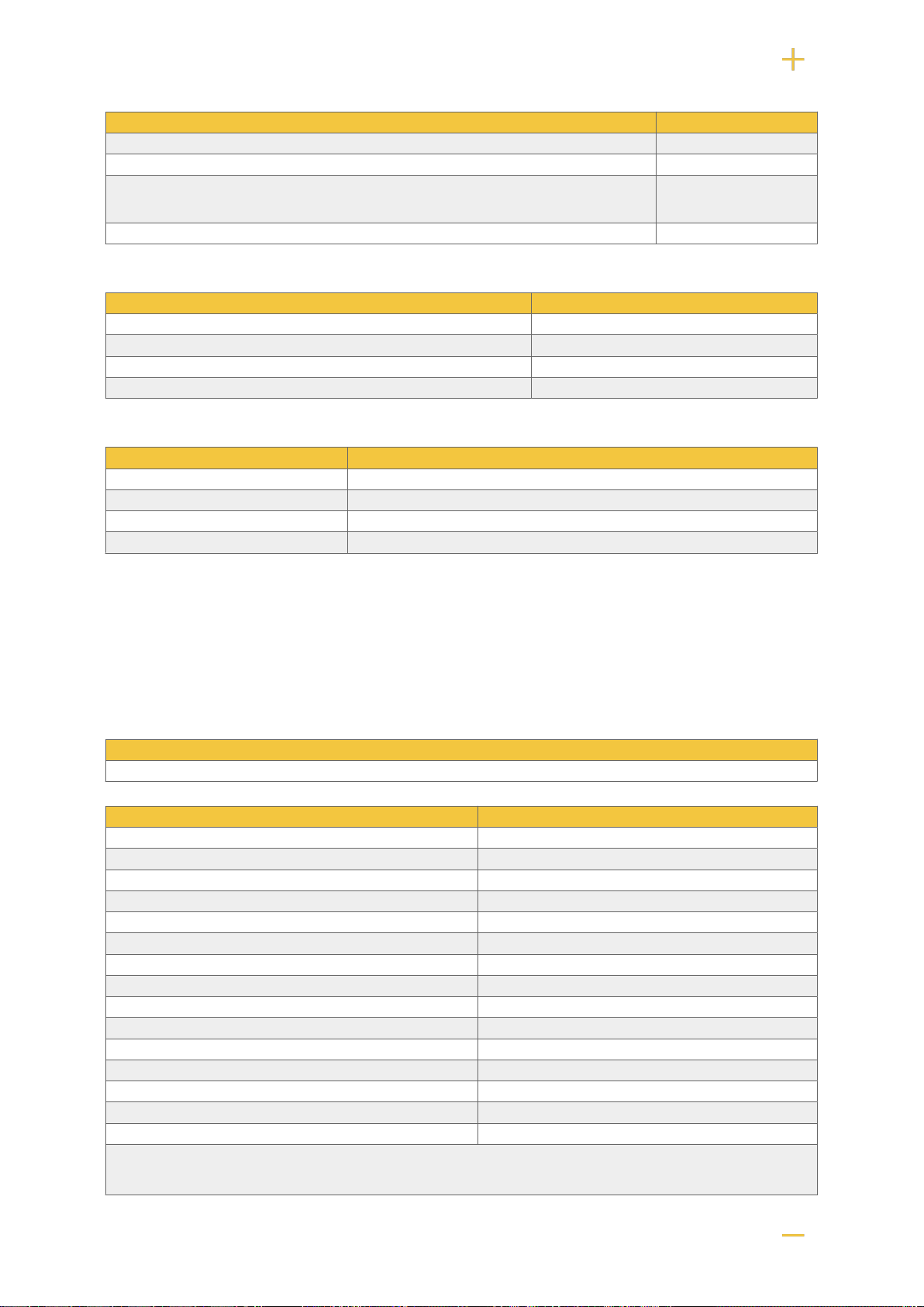
9.1.1. Alarm
Alarm displayed on indicator LED on the front of the cabinet.
• Cell fault in battery or unconnected battery.
• Charger fault, undervoltage.
• Charger fault, overvoltage.
• Low system voltage, system voltage below 24.0 V in mains operation.
• Low battery voltage, below 24.0 V DC, or mains interruption.
• Power failure alarm.
• Sabotage switch.
• Fuse fault.
• Aged battery
Expanding alarm functions are available via communication or with alarm cards.
Table 8. Outputs
Info Explanation
Alarm on alternating relay? (Yes No) Yes
Load outputs, number 2
Voltage at load output 27.3 V DC
Voltage limit, upper, on load output 27.9 V DC
Voltage limit, lower, on load output. For battery operation and disconnected mains voltage. 20 V DC
Priority (always voltage) load outputs (Yes / No)
Maximum load, per output 10 A
17
Info Explanation
Maximum load, total, (must not be exceeded). 10 A
Load output plus (+) secured? (Yes No) Yes
Load output minus (-) secured (Yes / No) Load output 1 = Yes
Load passage 2 = No.
Fuses on output Yes, see table: Fuses.
Table 9. Fuses
Fuse Type
15 A T15A
25 A T25A
Mains fuse for 24 V units up to 15 A T2.5AH250V. Ceramic.
Mains fuse for 24 v units over to 15 A T4AH250V. Ceramic.
Table 10. Protection
Electrical protection
Deep discharge protection (Yes / No) Yes. 12 V units protection at 10V, +/- 0.5 V. 24 V units protection at 20, +/- 0.5 V.
Surge protection (Yes / No) Yes
Overtemperature protection (Yes / No) Yes
Short circuit protected = (Yes / No) Yes
10. POWER SUPPLY
10.1. Power supply - Technical Data RSP-320-24
In:
NEO 24V 15A FLX L
Info Explanation
Output voltage 27.3 V
Output current 0 A - 13.4 A
Output voltage, ripple 150 mVp-p
Overvoltage 27.6 V - 32.4 V
Voltage recharge, ripple / current limitation Less than 1.2 Vp-p
Efficiency 89%
Current limitation 105% - 135%
Constant voltage +/- 0.5%
Regulatory accuracy +/- 1.0%
Input current (230 V) 2 A
Mains voltage frequency 47 Hz- 63 Hz
Mains voltage 230 V AC - 240 V AC
Brand effect 321.6 W
Temperature range -30°C - +70°C
Humidity range 20% - 90% RH non-condensed
The power supply is adapted and calibrated with the battery / hardware of the battery backup. Only power and calibrated power supplies may be used. Contact support when
changing power supplies. Use of power supplies coming from another source may cause damage not covered by the warranty. Warranty is canceled if power supplies (from a
source other than support / designated by support) that are not correctly calibrated are used.
18

10.2. Power supply - Technical Data HRP-600-24
In:
NEO 24V 25A FLX L
Info Explanation
Output voltage 27.3 V
Output current 0 A - 27 A
Output voltage, ripple 150 mVp-p
Overvoltage 30 V - 34.8 V
Voltage recharge, ripple / current limitation Less than 1.2 Vp-p
Efficiency 88%
Current limitation 105% - 135%
Constant voltage +/- 0.5%
Regulatory accuracy +/- 1.0%
Input current (230 V) 3,6 A
Mains voltage frequency 47 Hz- 63 Hz
Mains voltage 230 V AC - 240 V AC
Brand effect 648 W
Temperature range -30°C - +70°C
Humidity range 20% - 90% RH non-condensed
The power supply is adapted and calibrated with the battery / hardware of the battery backup. Only power and calibrated power supplies may be used. Contact support when
changing power supplies. Use of power supplies coming from another source may cause damage not covered by the warranty. Warranty is canceled if power supplies (from a
source other than support / designated by support) that are not correctly calibrated are used.
11. TECHNICAL DATA ENCLOSURES
11.1. Enclosures - Technical Data FLX L
Info Explanation
Name FLX L
Enclosure class IP 32
Measure Height: 444 mm, width 438 mm, depth 212 mm
Height units 10 HE
Mounting Wall or 19 "rack
Ambient temperature + 5 ° C - + 40 ° C. For best battery life: + 15 ° C to + 25 ° C.
Environment Environmental class 1, indoors. 20% ~ 90% relative humidity
Material Powder coated sheet
Color Black
Cable entries, number 4
Batteries that fit 2 st 12 V 45 Ah
Place for fan Yes
19
12. BATTERIES - RECOMMENDED, NOT INCLUDED
12.1. Batteries are not included they are sold separately
Batteries are sold separately.
12.2. 45 Ah, 12 V AGM battery
Fits in Number of batteries
Battery type V Ah
Maintenance-free AGM, lead-acid battery. 12 V 45 Ah
Table 11. 10+ Design life * battery
Article number E-number Article name Terminal Measure. Height
width depth Weight per
piece Make
MT113-12V45-01 5230546 UPLUS 12V 45Ah
10+ Design Life
battery
M5 Bult 197x165x170 mm 14.5 kg UPLUS
* Design Life is the durability this year for unused battery. Environmental factors such as heat and load affect service life. Batteries that
have a durability (+10 Design lLife) of 10+ years usually need to be replaced after 4-5 years.
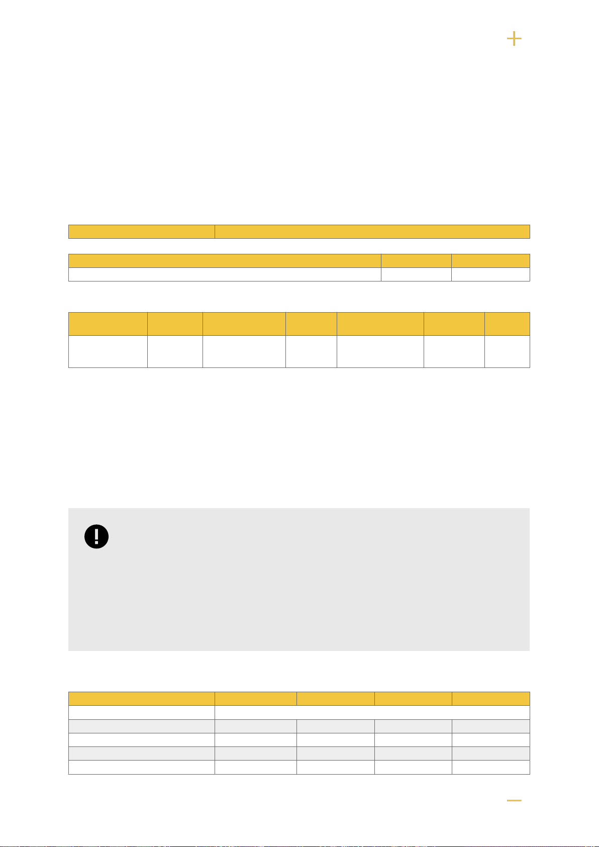
12.3. Reserve operating times for different alarm classes - overview
The table shows the requirements for backup operating time and recharging of batteries for different
alarm classes.
IMPORTANT
This is a guide and all times are approximate and may differ from actual times. Load,
temperature and other factors come into play, which is why exact time can not be
provided.
Applies to new batteries.
Amperage and batteries vary with configuration, check if the configuration can handle
batteries and amperage.
Table 12. Backup operating times 24 V units - without battery box
Medium current 7.2 Ah 14 Ah 28 Ah 45 Ah
Loading Backup operating time (approx.), Minutes
0.5 A 450 820 1650 2350
1 A 260 485 970 1460
2 A 150 280 560 920
4 A 90 165 335 550
20
Table of contents
Other milleteknik Batteries Pack manuals

Popular Batteries Pack manuals by other brands


Dexter Laundry
Dexter Laundry 12VBA2-20.5 Safety instructions

Parkside
Parkside 326390-1904 operating instructions

DARQ Matter
DARQ Matter Prism 2.6k user guide

BlackVue
BlackVue Power Magic Ultra Battery B-124 user manual

Wintersun
Wintersun WTS CORE Series Product Operating Manual

Yard force
Yard force AL G25 Original instructions