milleteknik PoE Switch 8p FLX M+ User manual

PoE Switch 8p FLX M+, PoE Switch 16p
FLX M+
PoE switch and powersupply with battery backup
EN

350-251
Publication date 2023-11-09

Table of Contents
1. Before you begin ........................................................................................................................ 4
1.1. Information ..................................................................................................................... 4
1.1.1. Support ................................................................................................................ 5
1.1.2. Link to the latest information .................................................................................. 5
1.1.3. Link to technical specifications .............................................................................. 5
1.1.4. Help us make better products ................................................................................ 5
2. About PoE from Milleteknik ......................................................................................................... 5
3. How PoE powers devices connected to the power supply ............................................................. 6
4. Component overview PoE FLX M ................................................................................................ 6
5. Console for FLX M and FLX L ..................................................................................................... 7
5.1. Mounting on a wall or in a 19 "rack ................................................................................... 7
6. Batteries - placement and connection .......................................................................................... 8
6.1. Connection of batteries in FLX S, FLX M and FLX L .......................................................... 8
7. Motherboard description ............................................................................................................. 9
7.1. Connect in this order ....................................................................................................... 9
7.2. Connect alarm on P3 ..................................................................................................... 10
7.3. Connect load ................................................................................................................ 10
7.4. Connect mains .............................................................................................................. 11
7.5. Control alarm limit ......................................................................................................... 12
7.6. Fuses ........................................................................................................................... 12
8. The differences between PoE switches ...................................................................................... 12
9. Short description for PoE switch 4p ........................................................................................... 12
10. Commissioning - how to start the unit ...................................................................................... 13
11. How the PoE switch software is accessed ................................................................................ 13
11.1. How the software is accessed in the PoE Switch ........................................................... 13
11.2. Log in to the PoE switch ............................................................................................... 16
11.3. Configuration .............................................................................................................. 17
11.3.1. System, configuration ....................................................................................... 17
11.3.2. Ports, configuration ........................................................................................... 18
11.3.3. VLAN configuration ........................................................................................... 20
11.3.4. Aggregation, configuration ................................................................................. 20
11.3.5. IGMP Snooping, configuration ........................................................................... 21
11.3.6. Mirroring, configuration ..................................................................................... 22
11.3.7. LLDP configuration ........................................................................................... 23
11.3.8. QoS, configuration ............................................................................................ 25
11.3.9. PoE, configuration ............................................................................................ 26
11.4. Monitoring ................................................................................................................... 27
11.4.1. Statistics, overview ........................................................................................... 27
11.4.2. Statistics, detailed ............................................................................................. 28
11.4.3. IGMP status ..................................................................................................... 29
11.4.4. LLDP statistics ................................................................................................. 30
11.4.5. LLDP table ....................................................................................................... 31
11.4.6. Ping ................................................................................................................. 32
11.5. Maintenance ............................................................................................................... 32
11.5.1. Reboot ............................................................................................................. 33
11.5.2. Factory reset .................................................................................................... 34
11.5.3. Upload new software ........................................................................................ 35
11.5.4. Load and save configuration file ......................................................................... 36
11.5.5. Log out ............................................................................................................ 37
12. Alarm displayed on cabinet door ............................................................................................. 37
13. Maintenance .......................................................................................................................... 38
13.1. battery change ............................................................................................................ 38
14. Product sheet - power supply / battery backup ......................................................................... 39
3

14.1. Product sheet - power supply from Milleteknik ............................................................... 39
14.1.1. Name, article number and e-number .................................................................. 39
14.1.2. PoE ................................................................................................................. 39
14.1.3. Description ....................................................................................................... 39
14.1.4. Area of use ...................................................................................................... 39
14.1.5. Voltage, current and power ................................................................................ 39
14.1.6. Backup operating time on batteries .................................................................... 40
14.1.7. Battery and battery type .................................................................................... 40
14.1.8. Load outputs .................................................................................................... 40
14.1.9. Alarm ............................................................................................................... 40
14.1.10. Protection ....................................................................................................... 40
14.1.11. Fuses ............................................................................................................. 40
14.1.12. Indications and communication ........................................................................ 40
14.1.13. Enclosure ....................................................................................................... 41
14.1.14. Weight ........................................................................................................... 41
14.1.15. Installation requirements ................................................................................. 41
14.1.16. Requirements that the product meets ............................................................... 41
14.1.17. Guarantee ...................................................................................................... 41
14.1.18. Expandable, options and accessories .............................................................. 41
14.1.19. Manufacturing, lifespan, environmental impact and recycling ............................. 41
14.1.20. Link to the latest information ............................................................................ 42
14.1.21. Link to technical specifications ......................................................................... 42
14.1.22. Miscellaneous ................................................................................................ 42
14.1.23. About this information ..................................................................................... 42
15. Product life cycle, environmental impact and recycling .............................................................. 42
16. Address and contact details .................................................................................................... 43
1. BEFORE YOU BEGIN
1.1. Information
READ THIS FIRST!
Electronics, regardless of enclosure, are intended for use in a controlled indoor envi-
ronment.
Ventilation must not be covered.
Only authorized persons should install and maintain the system.
It is the installer's responsibility to ensure that the system is suitable for its intended
use.
Documents accompanying the system must be kept in or in its immediate vicinity.
Mains voltage should be disconnected during installation.
All information subject to change.
Upon installation of this product, the installer acknowledges and accepts the limitations
of this product as described in this manual.
Instruction manual in Swedish in original1.
4

1.1.1. Support
Phone: +46 31-340 02 30
You will find answers to many questions at: www.milleteknik.se/support
Support is open: Monday-Thursday 08:00-16:00, Fridays 08:00-15:00. Closed 11:30-13:15.
1.1.2. Link to the latest information
Products and software are subject to updates, you will always find the latest information on our website.
PoE
1.1.3. Link to technical specifications
PoE M-switch 8p FLX M+ Swedish
PoE M-switch 8p FLX M+ English
PoE M-switch 16p FLX M+ Swedish
PoE M-switch 16p FLX M+ English
1.1.4. Help us make better products
With your help we can develop and produce better products, please fill in our form customer satisfaction
survey.
2. ABOUT POE FROM MILLETEKNIK
The series is designed to power PoE devices such as access systems, surveillance cameras and other
equipment that can be operated with Power over Ethernet.
PoE M-switch 4p FLX M, PoE M-switch 8p FLX M and PoE M-Switch 16p FLX M meet 802.3at type2
class 4. The PoE switch is managed, i.e. it is possible to control the switch via its software interface.
The products have something we call "controlled charging", which is a safety function that means that
batteries are not charged with more than 4.5 A. By controlling the charging of batteries, the lifespan
of batteries is significantly extended. The product has 24 V battery voltage which is boosted up to 48
V to power the PoE switch. There is a load output on the motherboard that provides 24V, this allows
the device to be used to power other applications such as door locks, etc on the one load output. It is
important to accurately calculate the load so that the unit's specifications are not exceeded. Battery box
can be connected for extended backup drive time.
1Translations in languages other than Swedish are only indicative and have not been verified. Translation must always be checked
against the Swedish original to ensure correct information.
5

3. HOW POE POWERS DEVICES CONNECTED TO THE
POWER SUPPLY
PoE can power, for example, surveillance cameras.
Connect external devices to be powered via PoE in PoE ports.
Connect other devices that do not need to be power supplied in LAN ports.
4. COMPONENT OVERVIEW POE FLX M
Figure 1. PoE M-switch 8p FLX M+
Figure 2. PoE M-switch 16p FLX M+
6

Table 1. Component overview
Symbol Explanation
A Brackets, reversible.
B Casing in powder-coated sheet metal.
C Power supply, (placed under the motherboard).
D Motherboard.
E Room for batteries.
F Eight PoE ports are clustered together and two LAN ports are clustered together.
G Cable entries.
5. CONSOLE FOR FLX M AND FLX L
Bracket is reversible and can be mounted in two ways. It comes with brackets in to the device.
5.1. Mounting on a wall or in a 19 "rack
The unit can be mounted in a 19 ”rack or on a wall. The included brackets can be attached in two
ways: When mounting on a wall, the brackets must sit backwards, against the wall. When mounting in a
19 ”rack, the console must be at the front edge of the unit.
7

Figure 3. FLX M - mount brackets
Left bracket facing the front for mounting in a 19 "rack.
Right bracket facing the back for wall mounting.
IMPORTANT
Leave 100 mm free around the air vents.
6. BATTERIES - PLACEMENT AND CONNECTION
6.1. Connection of batteries in FLX S, FLX M and FLX L
Battery wiring is mounted on the circuit board upon delivery. Pictures below only show how to connect
wiring.
1. Place the batteries in the cabinet with the battery terminals facing outwards.
2. Connect the battery cable. Red cable on + and black cable on -.
• If possible, disconnect mains voltage when replacing the battery.
8

Figure 4. Wiring diagram for batteries in battery backup
Connect the terminals correctly so that you do not damage the equipment.
7. MOTHERBOARD DESCRIPTION
7.1. Connect in this order
To minimize the risk of errors that may occur in connection with a short circuit, connections to the
motherboard must be made in this order.
Table 2. Connect in this order
Nr Explanation
1 Connect alarm.
2 Connect load.
3 Connect batteries
4 Connect mains.
9
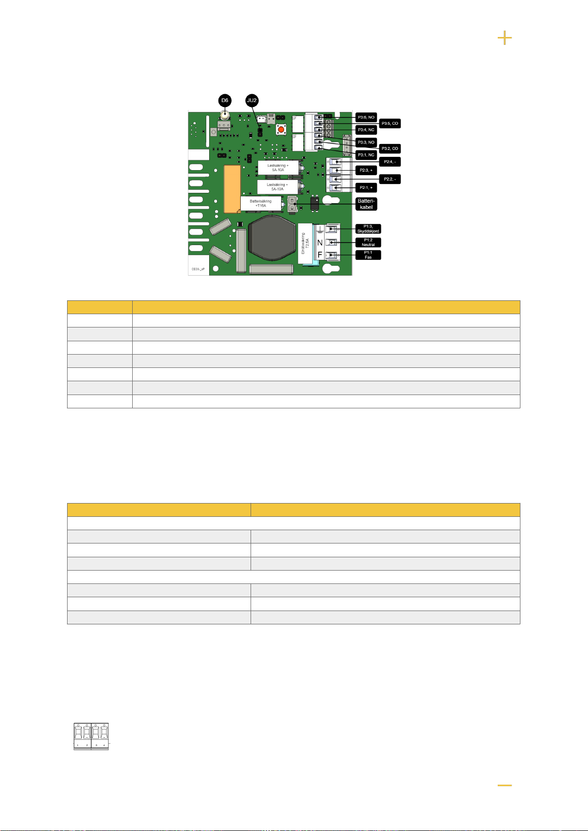
Figure 5. Description: CEO3 uP
On PCB Explanation
D6 Indicator diode.
JU2 Jumper for alarm control. When the jumper is mounted, the alarm limit is lowered.
P1:1-3 Mains connection.
P2:1-2 Load output, + / -.
P2:3-4 Load output, + / -.
P3:1-3 Alarm output, NC, CO, NO.
P3:4-6 Alarm output, NC, CO, NO.
7.2. Connect alarm on P3
Alarm is connected to terminal P3
Table 3. Connect alarm P3
P3:1-6 Explanation
Sum alarm
P3:1 NC
P3:2 Com
P3:3 NO
Sum-alarm*
P3:4 NC
P3:5 Com
P3:6 NO
Total alarm: Broken fuse on load, broken fuse from external distribution board, broken battery fuse, low
battery voltage in battery operation, batteries not connected, overvoltage.
7.3. Connect load
10

Table 4. Load connections
Circuit board number Explanation
P2: 1 Connection for load 1 +
P2: 2 Connection for load 1 -
P2: 3 Connection for load 2 +.
P2: 4 Connection for load 2 -.
MAX CURRENT
The maximum current must not be exceeded. Max current is indicated on nameplate
on the device.
DANGER
Mains voltage must be disconnected when working with stripped cables. It is the
installer's responsibility to ensure that the correct skills are available for connecting 230
V to the unit. Maximum cable area is 4 mm2
7.4. Connect mains
Pull wiring through the cable entry on the cabinet.
If possible, secure the mains cable with cable ties where possible.
Electrical network cabling shall be kept separate from other cabling to avoid EMC interference.
Figure 6. Connect the mains to the motherboard
Connect the mains cable to the terminal before it is put back on the motherboard. Secure F and N with
cable ties for electrical safety.
Table 5. Electrical network connections
Letter Explanation
F Phase
N Neutral
PE Protective earth
ELECTRICAL MAINS CONNECTION 230 V AC ON CIRCUIT
BOARD
Check that the marking on the circuit board matches the cable arrangement on the
terminal block.
11
7.5. Control alarm limit
Alarm for low battery voltage in battery operation can be controlled.
By jumpering JU2, the limit for when the unit should give an alarm can be lowered.
Alarms are given when the battery voltage in battery drops below the limit.
Table 6. Alarm limits
Alarm limit at low battery voltage 12 V 24 V
JU2 with jumper* 10.2 V 24.0 V
JU2 without jumper * 13.2 V 26.5 V
*The unit is delivered with jumper on JU2
7.6. Fuses
Unit Fuse Type Explanation
All units F1 T2,5A Mains fuse
F2, F6 T10A Load fuse +
All units F7 T16A Battery fuse
FUSE REPLACEMENT WARNING (A)
There is a risk of damage if the fuse is changed to a larger one than what the unit
is delivered with. The function of the fuse is to protect the connected load and cables
against damage and fire. It is not possible to change the fuse to a larger one to
increase the power output.
8. THE DIFFERENCES BETWEEN POE SWITCHES
Product PoE switch installed Can additional PoE switches be installed?
PoE M-switch 8p FLX M An eight port PoE Switch No, use PoE M-switch 16p FLX M.
PoE M-switch 16p FLX M Two eight-port PoE switches No.
9. SHORT DESCRIPTION FOR POE SWITCH 4P
NOTE
The PoE M-Switch 16p FLX M+ has two 8 port cards installed.
12

No Explanation
1 Not used.
2 2 pcs RJ-45 ports for data, not PoE, (powered).
3 8 pcs RJ-45 powered ports for connecting PoE devices.
A Indication, green LED lights up when device is plugged in. This is only an indication that the port is connected and not the
connected device's status.
B Indication, green LED lights up when PoE device is plugged in. This is only an indication that the port is connected and not
the connected device's status. Illuminates yellow during data transfer.
C Lights up green when the card has voltage.
10. COMMISSIONING - HOW TO START THE UNIT
1. Connect batteries.
2. Connect fuses.
3. Plug in PoE and other loads.
4. Screw the mains cable into the terminal and attach the terminal to the motherboard.
5. Switch on mains voltage.
The unit works normally when the indicator LED on the outside of the cabinet door lights up with a solid
green light. See front panel for other status indications.
It may take up to 72 hours before the batteries are fully charged.
11. HOW THE POE SWITCH SOFTWARE IS ACCESSED
11.1. How the software is accessed in the PoE Switch
This section shows how to log in to the switch's configuration web page.
In order to configure the software in the switch, access to the switch requires the correct IP address to
be set on the computer.
Access to the switch's software is through a browser (Chrome, Edge, Firefox).
Follow the steps to access the switch's settings.
13
NOTE
The settings shown are settings for PC, (Windows 7 - Windows 11). Windows and
names may vary between different versions of Windows. Unfortunately, we cannot
provide support for settings of your computer.
NOTICE
The address of the PoE switch is: 192.168.2.1 and username and password are: ad-
min/admin The IP address in the switch is static (fixed) and therefore the computer's
IP address and subnet mask must be static.
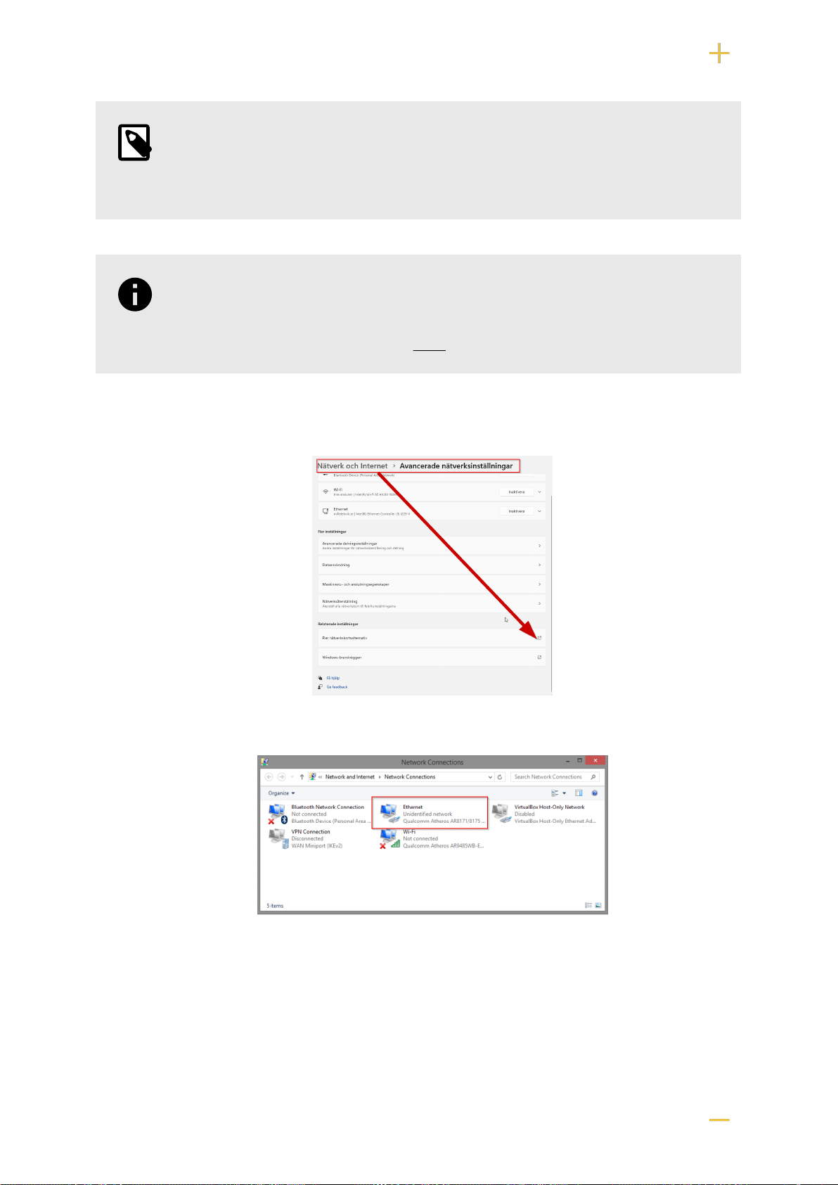
1. Open settings and go to Network and Internet -> Advanced network settings. Open more
network card options.
2. A Network Connections window will appear showing all available network connections on the
computer. Double-click the network connection you use to connect to the switch.
3. Ethernet status window appears. click the button Characteristics as shown in the figure below.
14

4. Double-click Internet Protocol Version 4 (TCP / IPv4).
5. Set the computer's IP address and subnet mask as shown in the figure below. By default, the
product's IP address be 192.168.2.1. You can set any IP address as long as it is not the same as
your switch's IP address and is in the same network segment as your switch's IP address. Press
OK to apply the TCP/IPv4 settings you just made. Now you can connect to your switch using a web
browser (Chrome, Edge or Firefox).
6. Connect an RJ-45 cable and connect to the PoE switch.
15

11.2. Log in to the PoE switch
NOTE
IP address of the switch (factory setting): 192.168.2.1
Password (factory setting): admin
1. Start the browser on your computer.
2. Login to PoE switch.
Number Explanation
1 IP address of the PoE switch: 192.168.2.1
2 Password: admin
3 Apply = Ok
4 Menu in the PoE switch
16

11.3. Configuration
11.3.1. System, configuration
Letter, number Explanation
A PoE switch system configuration page
A.1 Tick here if you are going to use DHCP, see warning below.
A.2 Changes the factory default password, (admin).
A.3 If you have made any changes, you need to click "Apply" to save the changes.
17

WARNING
The settings on this page normally do not need to be changed. Only change the
settings if you absolutely know what you are doing.
Factory reset the PoE device if it does not behave as expected after adjusting settings
on this page.
11.3.2. Ports, configuration
WARNING
The settings on this page normally do not need to be changed. Only change the
settings if you absolutely know what you are doing.
Factory reset the PoE device if it does not behave as expected after adjusting settings
on this page.
18

Letter, number Explanation
B Gates
B.1 This setting normally does not need to be changed. Select the speed of the PoE switch's ports.
B.2 This setting normally does not need to be changed.
19

11.3.3. VLAN configuration
WARNING
The settings on this page normally do not need to be changed. Only change the
settings if you absolutely know what you are doing.
Factory reset the PoE device if it does not behave as expected after adjusting settings
on this page.
Configuration of Virtual LAN.
11.3.4. Aggregation, configuration
WARNING
The settings on this page normally do not need to be changed. Only change the
settings if you absolutely know what you are doing.
Factory reset the PoE device if it does not behave as expected after adjusting settings
on this page.
20
This manual suits for next models
3
Table of contents
Other milleteknik Switch manuals


