DeLOCK 87704 User manual
Gigabit Ethernet Switch
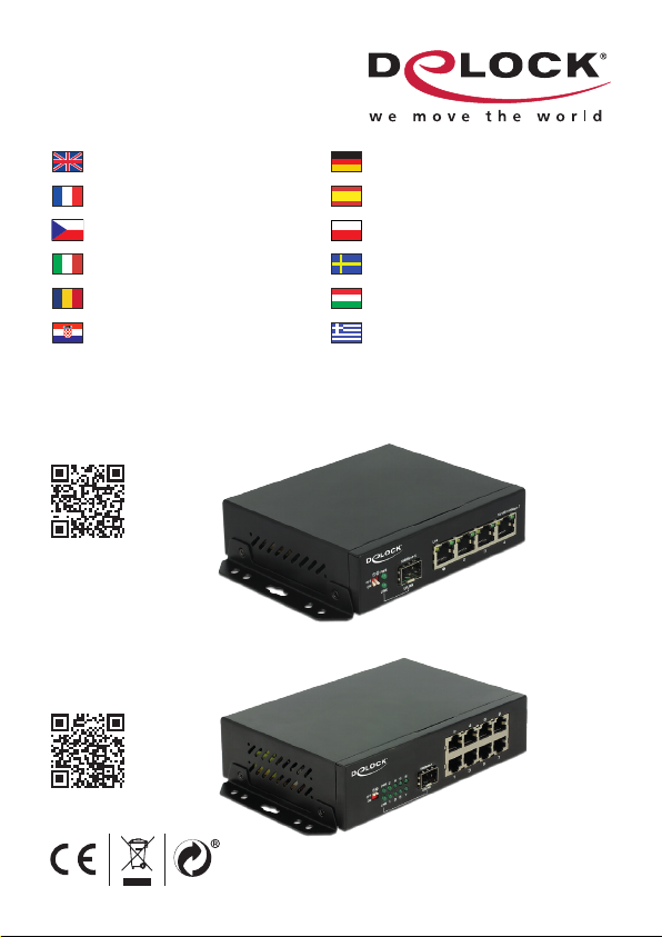
87704 - 4 Port + 1 SFP
87708 - 8 Port + 1 SFP
User manual no:87704-a
www.delock.com
User manual
Mode d’emploi
Uživatelská příručka
Manuale utente
Manual de utilizare
Korisnički priručnik
Bedienungsanleitung
Manual del usuario
Instrukcja obsługi
Bruksanvisning
Használati utasítás
Εγχειρίδιο χρήστη

-1-
English
Description
This Gigabit Ethernet Switch by Delock can be used to connect different network
components. In addition, the built-in SFP slot allows you to expand the network
with a ber optic connection.
Specication
• Connector:
4 x / 8 x RJ45 female for 10/100/1000 Mb/s Base-T
1 x SFP slot for 1 Gb/s SFP module (SFP module not included)
1 x IEC C14 connector
• Data transfer rate up to 1 Gb/s
• Supports IEEE 802.3 / 802.3u / 802.3z / 802.3ab
• LEDs for status monitoring
• VLAN (port isolation or 1:1 mode) selectable by DIP switch
• 330 m long range mode with 10 Mb/s
• Robust metal housing
• Removable wallmount brackets
• Fanless
• Internal power supply
• Power consumption: max. 10 W
• Operating temperature: -20 °C ~ 60 °C
• Dimensions (LxWxH): ca. 125 x 109 x 32 mm
System requirements
• Device with one free RJ45 port
Package content
• Switch
• Wall mounting brackets
• Power cord
• User manual

-2-
English
Installation
• TP interface
Connect the network devices with TP cable to the RJ-45 ports of the switch.
• SFP interface
Slide the optional SFP module into the SFP slot and push until you hear a click.
Connect a ber cable from the SFP module to the ber network.
• Power
Connect the included power cable to the switch and check that the Power LED
lights up.
• DIP Switch settings
DIP1 DIP2 Mode
OFF OFF Default
ON OFF Video Channel
OFF ON VLAN Port Isolation
ON ON Long distance
1. Default mode
DIP switch 1 and 2 are by factory default both in OFF position; the uplink and
downlink ports are interconnected.
2. Video channel mode
When two identical switches A and B are connected through the uplink port,
the data port 1 of device A is connected to port 1 of device B. Ports 2 – 4 are
connected the same way. All ports on the same switch are isolated from each
other, but they can communicate to the same port of the corresponding switch.
Note: When connecting a 4-port switch to an 8-port switch, the corresponding
ports are: Port 1 > Port 6, Port 2 > Port 3, Port 3 > Port 4 and Port 4 > Port 1.
3. One Key VLAN (Port Isolation)
Data forwarding is not available between the copper ports of the switch, they can
only communicate with the uplink port, ensuring effective data transfer and a safe
system.
4. Long distance mode
In default state, the transmission distance of the copper ports is up to 100 m.
When long distance mode is activated, the transmission rate of the RJ45 ports is
limited to 10 Mb/s, while increasing the max transmission distance to 330 m.

-3-
English
Support Delock
If you have further questions, please contact our customer support
You can nd current product information on our homepage: www.delock.com
Final clause
Information and data contained in this manual are subject to change without
notice in advance. Errors and misprints excepted.
Copyright
No part of this user manual may be reproduced, or transmitted for any purpose,
regardless in which way or by any means, electronically or mechanically, without
explicit written approval of Delock.
Edition: 12/2016

-4-
Deutsch
Kurzbeschreibung
Mit diesem Gigabit Ethernet Switch von Delock können verschiedene
Netzwerkkomponenten verbunden werden. Zusätzlich bietet der eingebaute SFP-
Schacht die Möglichkeit, das Netzwerk um einen Lichtwellenleiter-Anschluss zu
erweitern.
Spezikation
• Anschlüsse:
4 x / 8 x RJ45 Buchse für 10/100/1000 Mb/s Base-T
1 x SFP Schacht für 1 Gb/s SFP Modul (SFP Modul nicht im Lieferumfang
enthalten)
1 x Kaltgeräteeinbaustecker
• Datentransferrate bis zu 1 Gb/s
• Unterstützt IEEE 802.3 / 802.3u / 802.3z / 802.3ab
• LEDs zur Statuskontrolle
• VLAN (Port Isolation oder 1:1 Modus) über DIP-Schalter einstellbar
• 330 m Long Range Modus mit 10 Mb/s
• Robustes Metallgehäuse
• Abnehmbare Wandbefestigung
• Lüfterlos
• Internes Netzteil
• Leistungsaufnahme: max. 10 W
• Betriebstemperatur: -20 °C ~ 60 °C
• Maße (LxBxH): ca. 125 x 109 x 32 mm
Systemvoraussetzungen
• Gerät mit einem freien RJ45 Anschluss
Packungsinhalt
• Umschalter
• Wandmontage Winkel
• Netzkabel
• Bedienungsanleitung

-5-
Deutsch
Installation
• TP Schnittstelle
Schließen Sie die Netzwerkgeräte mit TP Kabel an die RJ-45 Buchsen des
Switches an.
• SFP Schnittstelle
Schieben Sie das optionale SFP Modul in den SFP Schacht, bis es hörbar
einrastet. Schließen Sie ein LWL Kabel zwischen dem SFP Modul und dem
Netzwerk an.
• Power
Schließen Sie das mitgelieferte Netzkabel an den Switch an und kontrollieren
Sie, dass die Power LED aueuchtet.
• DIP-Schalter-Einstellungen
DIP1 DIP2 Modus
OFF OFF Standard
ON OFF Videokanal
OFF ON VLAN Port Isolation
ON ON Langstrecke
1. Standardmodus
DIP-Schalter 1 und 2 sind werkseitig in der Position OFF; die Uplink- und
Downlink-Ports sind untereinander verbunden.
2. Videokanalmodus
Wenn zwei identische Switche A und B über den Uplink-Port verbunden sind, ist
der Port 1 von Gerät A mit dem Port 1 von Gerät B verbunden. Die Anschlüsse 2
- 4 sind auf die gleiche Weise verbunden. Alle Ports auf demselben Switch sind
voneinander isoliert, können aber mit dem gleichen Port des korrespondierenden
Switches kommunizieren. Hinweis: Wenn Sie einen 4-Port-Switch an einen
8-Port-Switch anschließen, sind die verbundenen Ports: Port 1 > Port 6, Port 2 >
Port 3, Port 3 > Port 4 und Port 4 > Port 1.
3. Ein-Tasten VLAN (Port-Isolation)
Eine Datenübertragung zwischen den Kupfer-Ports des Switches ist nicht
möglich; sie können nur mit dem Uplink-Port kommunizieren, wodurch eine
effektive Datenübertragung und ein sicheres System erreicht wird.

-6-
Deutsch
4. Langstreckenmodus
Im Standardmodus beträgt die Übertragungsreichweite der Kupferanschlüsse bis
zu 100 m. Wenn der Langstreckenmodus aktiviert ist, wird die Übertragungsrate
der RJ45 Anschlüsse auf 10 Mb/s beschränkt, während der maximale
Übertragungsabstand auf 330 m erhöht wird.
Support Delock
Bei weitergehenden Supportanfragen wenden Sie sich bitte an
Aktuelle Produktinformationen und Treiber Downloads nden Sie auch auf
unserer Homepage: www.delock.de
Schlussbestimmung
Die in diesem Handbuch enthaltenen Angaben und Daten können ohne vorherige
Ankündigung geändert werden. Irrtümer und Druckfehler vorbehalten.
Copyright
Ohne ausdrückliche schriftliche Erlaubnis von Delock darf kein Teil dieser
Bedienungsanleitung für irgendwelche Zwecke vervielfältigt oder übertragen
werden, unabhängig davon, auf welche Art und Weise oder mit welchen Mitteln,
elektronisch oder mechanisch, dies geschieht.
Stand: 12/2016

-7-
Français
Description
Ce commutateur Gigabit Ethernet de Delock peut servir à connecter différents
composants réseau. De plus, l'emplacement SFP intégré vous permet d'étendre
le réseau avec une connexion par bre optique.
Spécications techniques
• Connecteur :
4 x / 8 x RJ45 femelle pour 10/100/1000 Mb/s Base-T
1 x emplacement SFP pour module SFP 1 Gb/s (Module SFP non inclus)
1 x connecteur IEC C14
• Débit de données jusqu'à 1 Gb/s
• Prise en charge IEEE 802.3 / 802.3u / 802.3z / 802.3ab
• LED pour surveillance de l’état
• VLAN (isolation de port ou mode 1:1) sélectionnable via commutateur DIP
• Mode longue portée 330 m avec 10 Mb/s
• Logement métallique robuste
• Supports amovibles pour montage mural
• Sans ventilateur
• Alimentation électrique interne
• Consommation en puissance : maxi. 10 W
• Température de fonctionnement : -20 °C ~ 60 °C
• Dimensions (LxlxH) : env. 125 x 109 x 32 mm
Conguration système requise
• Appareil avec un port RJ45 libre
Contenu de l’emballage
• Commutateur
• Supports de montage mural
• Câble d'alimentation
• Mode d’emploi
Installation
• Interface TP
Connectez les périphériques réseau avec le câble TP aux ports RJ-45 du
commutateur.
• Interface SFP
Faites coulisser le module SFP optionnel dans l'emplacement SFP et poussez
jusqu'à ce que vous entendiez un déclic. Connectez un câble bre depuis le
module SFP jusqu’au réseau bre.

-8-
Français
• Alimentation
Branchez le câble d'alimentation inclus sur le commutateur et vériez que la
LED d'alimentation s'allume.
• Réglages du commutateur DIP
DIP1 DIP2 Mode
ARRÊT ARRÊT Par défaut
MARCHE ARRÊT Canal vidéo
ARRÊT MARCHE Isolation port VLAN
MARCHE MARCHE Longue distance
1. Mode par défaut
Les commutateurs DIP 1 et 2 sont réglés tous les deux par défaut en usine
sur la position ARRÊT ; les ports liaison montante et liaison descendante sont
interconnectés.
2. Mode canal vidéo
Lorsque deux commutateurs A et B identiques sont connectés via le port
liaison montante, le port données 1 du périphérique A est connecté au port 1
du périphérique B. Les ports 2 à 4 sont connectés de la même façon. Tous les
ports sur le même commutateur sont isolés les uns des autres, mais ils peuvent
communiquer sur le même port du commutateur correspondant. Remarque : En
cas de connexion d'un commutateur 4 ports à un commutateur 8 ports, les ports
correspondants sont : Port 1 > Port 6, Port 2 > Port 3, Port 3 > Port 4 et Port 4 >
Port 1.
3. VLAN une touche (Isolation de port)
Le transfert de données n'est pas disponible entre les ports cuivre du
commutateur, ils peuvent uniquement communiquer avec le port liaison montante,
garantissant un transfert de données efcace et un système sûr.
4. Mode longue distance
Dans l'état par défaut, la distance de transmission des ports cuivre va jusqu'à
100 m. Lorsque le mode longue distance est activé, le taux de transmission des
ports RJ45 est limité à 10 Mb/s, tout en augmentant la distance de transmission
maximale à 330 m.

-9-
Français
Assistance Delock
Si vous avez d'autres questions, veuillez contacter notre assistance client :
Vous pouvez trouver les informations sur nos produits actuels sur notre page
d'accueil : www.delock.fr
Clause nale
Les informations et données contenues dans ce manuel sont sujettes à
modications sans préavis. Sont exclues les erreurs et les fautes d'impression.
Copyright
Aucune partie de ce manuel d'utilisation ne peut être reproduite ou transmise,
quel qu'en soit le but, et sous quelque moyen que ce soit, électronique ou
mécanique, sans l'approbation écrite expresse de Delock.
Version : 12/2016
This manual suits for next models
1
Table of contents
Languages:
Other DeLOCK Switch manuals

DeLOCK
DeLOCK 64155 User manual

DeLOCK
DeLOCK 63739 User manual

DeLOCK
DeLOCK 11482 User manual

DeLOCK
DeLOCK 11367 User manual

DeLOCK
DeLOCK 11500 User manual

DeLOCK
DeLOCK 64234 User manual

DeLOCK
DeLOCK 87729 User manual

DeLOCK
DeLOCK 87765 User manual

DeLOCK
DeLOCK 63261 User manual

DeLOCK
DeLOCK 62900 User manual

DeLOCK
DeLOCK 11367 User manual

DeLOCK
DeLOCK 62793 User manual

DeLOCK
DeLOCK 11476 User manual

DeLOCK
DeLOCK 87758 User manual

DeLOCK
DeLOCK 64236 User manual

DeLOCK
DeLOCK 62653 User manual

DeLOCK
DeLOCK 63264 User manual

DeLOCK
DeLOCK 87699 User manual

DeLOCK
DeLOCK 11481 User manual

DeLOCK
DeLOCK 88015 User manual


