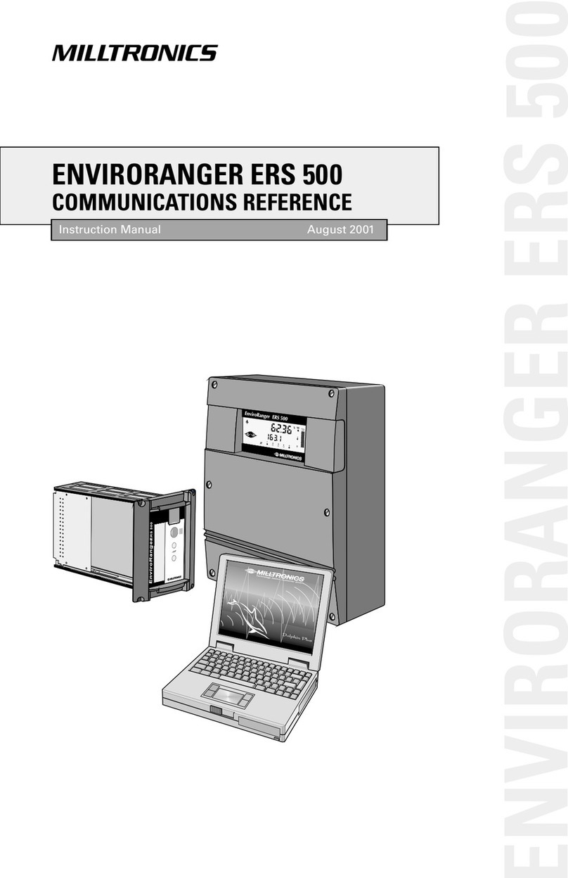
Milltronics EnviroRanger ERS500 User manual

33456030
Rev. 1.3
ENVIRORANGER ERS 500
PARAMETER REFERENCE
Instruction Manual PL-603 April 2001
ENVIRORANGER ERS 500

© Siemens Milltronics Process Instruments Inc. 2001
Safety Guidelines
Warning notices must be observed to ensure personal safety as well as that of others, and to
protect the product and the connected equipment. These warning notices are accompanied
by a clarification of the level of caution to be observed.
Qualified Personnel
This device/system may only be set up and operated in conjunction with this manual.
Qualified personnel are only authorized to install and operate this equipment in accordance
with established safety practices and standards.
Warning: This product can only function properly and safely if it is correctly transported,
stored, installed, set up, operated, and maintained.
Note: Always use product in accordance with specifications.
Copyright Siemens Milltronics Process
Instruments Inc. 2000. All Rights Reserved Disclaimer of Liability
This document isavailable inbound version and in
electronic version. We encourage users to
purchase authorized bound manuals, or to view
electronic versions as designed and authored by
Siemens Milltronics Process Instruments Inc.
Siemens Milltronics Process Instruments Inc. will
not be responsible for the contents of partial or
whole reproductions of either bound or electronic
versions.
While we have verified the contents of
this manual for agreement with the
instrumentation described, variations
remain possible. Thus we cannot
guarantee full agreement. The
contents of this manual are regularly
reviewed and corrections are included
in subsequent editions. We welcome
all suggestions for improvement.
Technical data subject to change.
MILLTRONICS®is a registered trademark of Siemens Milltronics Process Instruments Inc.
Contact SMPITechnical Publications at thefollowing address:
Technical Publications
Siemens Milltronics Process Instruments Inc.
1954 Technology Drive, P.O. Box 4225
Peterborough, Ontario, Canada, K9J 7B1
Email: techpubs@milltronics.com
For the library of SMPI instruction manuals, visit our Web site: www.milltronics.com

PL-603 EnviroRanger Parameter Reference Page 3
Table of Contents
About the EnviroRanger ERS 500…........................................................5
About the Parameter Reference….......................................................5
Using this Manua…............................................................................6
About Configuring ERS 500 Parameters… ..........................................6
About Power Interruptions…...............................................................6
Parameter Reference...............................................................................7
Quick Start (P001 to P009) .................................................................7
Voume (P050 to P055).....................................................................12
Dispay and Reading (P060 to P062).................................................16
Faisafe (P070 to P072) ....................................................................18
Reays (P100 to P119)......................................................................19
Pump Setpoint Modifiers (P121 and P122) ........................................25
Independent Reay Faisafe (P129)....................................................26
Advanced Pump Contro Modifiers (P130 to P136)..............................27
Pump Energy Cost Reduction (P140 to P145) ...................................29
Energy Cost Reduction Override (P148 to P149)...............................33
Overf ow / Underf ow (P160 to P169).................................................34
Fush Systems (P170 to P173)..........................................................37
Pump Efficiency (P180 to P186)........................................................39
mA Output (P200 to P219)................................................................41
Independent mA Setpoints (P210 and P211) .....................................43
mA Output Limits (P212 and P213) ...................................................44
mA Output Trim (P214 to P215)........................................................44
mA Output Faisafe (P219)................................................................45
mA Input (P250 to P254)...................................................................45
mA Input Trim (P260 to P262)...........................................................47
Discrete Input Functions (P270 to P275)............................................48
Standard Data Logging (P300 to P321).............................................50
Record Temperatures (P300 to P303)...............................................51
Record Readings (P304 and P305)...................................................52
Pump Records (P309 to P312)..........................................................52
Overf ow / Underf ow Records (P313 to P316)...................................54
Fow Records (P320 and P321).........................................................56
LCD Tota izer (P322 and P323).........................................................56
Profie Records (P330 to P337).........................................................57
Auto Record “On” and “Off” Setpoints (P334 to P337)............................59
Insta ation Records (P340 to P342)..................................................61
Enabing Optiona Features (P343 to P348).......................................62
Aarm and Event Trigger System (P420 to P430)...............................63
Trigger A arm Logging System (P431 to P435)..................................64
Data Logging Parameters (P440 to P453) .........................................66
Statistica Cacu ations (P454 to P458)..............................................70
Report by Exception (P470 to P472)..................................................72
ModBus Master (P473 to P476) ........................................................74
Report Generation (P481 to P485)....................................................75
Pump Interock A ocation (P500 to P509)..........................................77
Pump Faut Status (P510 to P515)....................................................83
Pump Contro Source (P520 to P524)................................................86

Page 4 EnviroRanger Parameter Reference PL-603
OCM (P600 to P621)........................................................................88
Pumped Voume Totaizer (P622 to P623).........................................95
Totaizer (P630 to P645)...................................................................97
Range Ca ibration (P650 to P654)................................................... 100
Temperature Compensation (P660 to P664).................................... 102
Rate (P700 to P708).......................................................................104
Measurement Verification (P710 to P713)........................................ 108
Transducer Scanning (P726 to P728).............................................. 110
Dispay (P730 to P739)................................................................... 111
SmartLinx Reserved (750 to 769).................................................... 113
Communications (P770 to P782).....................................................114
Dia er Parameters (P783 to P789).................................................. 118
SmartLinx Hardware Testing (P790 – P792).................................... 120
Echo Processing (P800 to P807)..................................................... 121
Advanced Echo Processing (P810 to P825)..................................... 124
Profie Pointer (P817 to P825).........................................................126
Advanced TVT Adjustment (P830 to P835)...................................... 130
Advanced Shot Adjustment (P840 to P852).....................................132
Test (P900 to P913)........................................................................ 135
Measurement (P920 to P927) ......................................................... 138
Master Reset (P999)....................................................................... 140
Appendix ............................................................................................. 14
Index types..................................................................................... 142
Index.................................................................................................... 144

PL-603 EnviroRanger Parameter Reference Page 5
Introduction
About the EnviroRanger ERS 500…
The EnviroRanger is intended for advanced water and wastewater
appications. This device can hand e virtua y a of your pump contro and
eve monitoring needs – often repacing expensive PLCs and integrating into
a SCADA system for a fraction of the cost of competitive systems.
The EnviroRanger is programmable.
It can be configured for neary any water or wastewater app ication, contro
up to five pumps, gates, or a arms – and can communicate its status by way
of direct seria connection, modem, or industria communication network.
The EnviroRanger is flexible.
It can take discrete input from pumps or other devices to modify its
operation, and can a so time events to maximize efficiency or minimize cost.
The EnviroRanger is upgradeable.
Its basic features can be further enhanced with any of the fo owing:
Hard are Upgrades
• I/O Anaog Cards
• RAM memory
• Discrete inputs
Soft are Upgrades
• Dua Point
• Data Logging
About the Parameter Reference…
This is the third in the series of four manua s in the ERS ibrary.
Manual Uses
User Guide
(PL-600)
• Learn how to program the unit
• Example applications
• Principles of operation
Installation Guide
(PL-601)
• Outline diagrams
• Wiring diagrams
• nstallation requirements
Communications Reference
(PL-602)
• MODBUS register mapping
• Modem configuration
Parameter Reference
(PL-603)
• Parameter values
• Parameter uses

Page 6 EnviroRanger Parameter Reference PL-603
Introduction
Using this Manual…
Information Section Page
Find information about a parameter. Parameter Reference 7
To look up a concept or keyword. Index 144
Note: Factory settings or preset values are marked with the *.
About Configuring ERS 500 Parameters…
The primary method of configuring the EnviroRanger is using Milltronics
Dolphin Plus software and a serial connection to the device.
Configuring the EnviroRanger using the optional Hand Programmer is
possible but is not recommended for complex installations.
As a rule of thumb, if your application falls into one of the pre-configured
applications outlined in the EnviroRanger User Guide, then use the hand
programmer. If your application is more complex than this, then we suggest
that you use Dolphin Plus. To purchase a copy of Dolphin Plus, contact your
Milltronics representative.
About Power Interruptions…
All operator programming is stored in non-volatile memory, and is unaffected
by power interruptions. Reporting functions use volatile RAM with battery
backup.

PL-603 EnviroRanger Parameter Reference Page 7
Parameter Reference
Parameter Reference
P000 Lock
Use this parameter to secure the EnviroRanger from changes.
Primary Index global
1954 * off (programming permitted)
-1 simulation controls (relays energize based on simulated
level)
Value
other lock activated (programming secured)
Related • P132 Pump Start Delay on page 28
• Simulation in the EnviroRanger User Guide.
WARNING
Use this lock as backup security only. It uses a fixed value which can
be discovered by unauthorized personnel.
Access this parameter direct y (type the number 000) and enter any va ue
(other than 1954) to secure the programming ock. To unock the
EnviroRanger, access this parameter and enter the va ue “1954”.
Quick Start (P001 to P009)
P001 Operation
Sets the type of measurement required for the application.
Standard Mode Dual Point Mode
Primary Index
global level
0 Out-of-service
1 Level – how full the vessel is (a.k.a. volume – P050)
2 Space – how empty the vessel is (a.k.a. ullage – P050)
3 * Distance – distance from transducer to material
4 DPD – dual point difference
5 DPA – dual point average
6 OCM – flow rate in an open channel
Value:
7 Pump Totalizer – total pumped volume
Alters • P600 Primary Measuring Device on page 88
If you have Single Point Mode (base unit)…
Norma y there is a singe eve measurement point and a re evant
parameters are g oba. For “DPD” or “DPA” operation, either 2 transducers of
the same type are required, or one transducer and one mA input. If two

Page 8 EnviroRanger Parameter Reference PL-603
Parameter Reference
transducers are used, a transducer parameters become indexed, and a
third eve point is ca cu ated.
• DPD (difference) = Point 1 - Point 2
• DPA (average) = (Point 1 + Point 2) / 2
For these operations any of three eve points (transducer 1, transducer 2, or
the cacu ated point) can be used to trigger reays (see P110 Leve Source
on page 20).
If you have Dual Point Mode (optional)…
With the Dua Point option insta ed the EnviroRanger is abe to contro three
independent app ications – one on each transducer pus the ca cu ated eve .
Each app ication type is defined in P001 on index 1, 2, or 3.
Operation [index] Available Values
P001[1] 1, 2, 3, 6, 7
P002[2] 1, 2, 3, 6, 7
P003[3] 4, 5
So, when programming a unit with the Dua Point option you can specify any
of the three eve points (transducer 1, transducer 2, or the cacuated eve
point) for any parameter indexed by “ eve ”.
P002 Material
The type of material being measured, normally liquid.
Standard Mode Dual Point Mode
Primary Index global transducer
1 * Liquid or horizontal solid surface
Values 2 Solid or angled surface
Alters • P830 TVT Type on page 130
For most EnviroRanger appications this entry wi be iquid or surry (va ue 1)
but the appication cou d aso invove so ids.
P003 Maximum Process Speed
Determines how quic ly the EnviroRanger reacts to level changes.
Primary Index transducer
1 Slow (0.1 m/min)
2 * Medium (1 m/min)
Values:
3 Fast (10 m/min)

PL-603 EnviroRanger Parameter Reference Page 9
Parameter Reference
Alters
• P070 Failsafe Timer on page 18
• P700 Max Fill Rate on page 104
• P701 Max Empty Rate on page 105
• P702 Filling ndicator on page 105
• P703 Emptying ndicator on page 105
• P704 Rate Filter on page 106
• P710 Fuzz Filter on page 108
• P713 Echo Lock Window on page 109
• P727 Scan Delay on page 110
• P841 Long Shot Number on page 133
Related
• Failsafe (P070 to P072) on page 18
• P121 Pump by Rate on page 25
• Measurement Verification (P710 to P713) on page 108
• Transducer Scanning (P726 to P728) on page 110
• Rate (P700 to P708) on page 104
• P905 Transmit Pulse on page 136
Use the setting which is just fast enough to keep up with your process.
Sower settings provide higher accuracy whie faster settings a ow for more
eve f uctuations.
P004 Transducer
Specifies the Milltronics transducer connected to the unit.
Standard Mode Dual Point Mode
Primary Index
global transducer
0 * No transducer attached (preset for Dual Point)
1 ST-25
2 ST-50
100 STH
101 XCT-8
102 * XPS-10 (preset for Standard Mode)
103 XCT-12
104 XPS-15
112 XRS-5
250 Auxiliary mA input #1
Values
251 Auxiliary mA input #2 (see note below)
Related
• mA nput (P250 to P254) on page 41
• P842 Short Shot Frequency on page 133
• P843 Long Shot Frequency on page 133
• P844 Short Shot Width on page 134
• P845 Long Shot Width on page 134
• P852 Short Shot Range on page 135
Enter the type of transducer(s) connected to the EnviroRanger. If mu tipe
transducers are used they must be of the same type.
Note:
Auxiiary mA input #2 is ony avaiabe if cards 2I/2O or card 4AI are used.

Page 10 EnviroRanger Parameter Reference PL-603
Parameter Reference
P005 Units
Specifies the units used for dimensional values.
Primary Index global
1 * Meters
2 Centimeters
3 Millimeters
4 Feet
Values:
5 nches
Alters
• P006 Empty on page 10
• P007 Span on page 11
• P060 Decimal Position on page 16
• P603 Maximum Head on page 90
• P605 Zero Head on page 91
• P620 Low Flow Cutoff on page 94
• P921 Material Measurement on page 139
• P926 Head Measurement on page 140
• P927 Distance Measurement on page 140
Changing this vaue automatica y changes the units disp ayed for many
parameters. Existing va ues are converted and do not have to be re-entered.
P006 Empty
The distance in “units” (P005) from the face of the transducer to the process
empty point.
Primary Index transducer
Range: 0.000 to 9999
Values Preset: 5.000m (or equivalent depending on units)
Alters • P007 Span on page 10
Altered By • P005 Units on page 10
Related
• P800 Near Blanking on page 121
• P921 Material Measurement on page 139
• P927 Distance Measurement on page 140
Setting this va ue aso sets Span (P007) uness Span was a ready set to
another va ue.

PL-603 EnviroRanger Parameter Reference Page 11
Parameter Reference
P007 Span
Span is the range of levels that the equipment is set to measure.
Primary Index level
Range: 0.0 to 9999
Values Preset: based on Empty (P006)
Alters
• P605 Zero Head on page 91
• P112 Relay “on” Setpoint on page 21
• P113 Relay “off” Setpoint on page 21
Altered By • P005 Units on page 10
• P006 Empty on page 10
Related
• Volume (P050 to P055) on page 12
• P800 Near Blanking on page 121
• P921 Material Measurement on page 139
• P922 Space Measurement on page 139
• P926 Head Measurement on page 140
Span is preset for a vaue cose to the maximum avaiab e. Enter a va ue that
ref ects the maximum range of your appication.
Aways prevent the monitored surface from approaching within 0.33 m (1 ft)
of the transducer face as this is the minimum banking for most Mi tronics
transducers (some require more b anking – see your transducer manua ).
Many other parameters are set as a percentage of span (even if they are
entered in units). The va ues of these other parameters may change if the
span is atered after insta ation and they are measured based on eve
(upwards from Empty towards the transducer face).
A vo umes are based on span so it shou d be set for the maximum vo ume
point if vo ume cacu ations are needed.
P008 Date
Date is the current date in the format: YY:MM:DD.
Primary Index global
Values Range: 70:01:01 to 69:12:31
Related • P009 Time on page 12.
The date is entered using the numeric keypad and the decima “ ” key. For
examp e, to enter December 10, 1998 type in the va ue “98.12.10”.

Page 12 EnviroRanger Parameter Reference PL-603
Parameter Reference
Display Date Time
Wall mount
Rack or
Panel
Year 2000 Compliance
00-69 Assumed to be the years 2000 to 2069
70-99 Assumed to be the years 1970 to 1999
P009 Time
Time is the current time in 24-hour format: HH:MM:SS.
Primary Index global
Values Range: 00:00:00 to 23:59:59
Related • P008 Date on page 11.
The time is entered using the numeric keypad and the decima “ ” key. For
examp e, to enter 9:34:45 p.m. you woud type in the vaue “21.34.45”.
Volume (P050 to P055)
To enab e the EnviroRanger to show readings based on vesse or wet we
voume (rather than eve) use these parameters.
P050 Tank Shape
Enter the Tan Shape value that matches the monitored vessel or wet well.
When Operation is " eve " (P001 = 1), iquid (materia) voume is ca cu ated.
Aternative y, when Operation is "space" (P001 = 2), remaining vesse
capacity is ca cu ated.
day
month
year
seconds
minutes
hours
day
month
year
minutes
hours
seconds

PL-603 EnviroRanger Parameter Reference Page 13
Parameter Reference
In the RUN mode, Readings are disp ayed in percent of maximum vo ume.
To convert Readings to vo umetric units, see Max Voume (P051).
Standard Mode Dual Point Mode
Primary Index global transducer
# Shape Description
0 * volume calculation not required
(preset)
1
flat level bottom
2
cone / pyramid bottom
Values
3
parabola bottom
# Shape Description
4
half sphere bottom
5
flat sloped bottom
6
flat ends
7
parabola ends
8
sphere
9
universal linear
Values (cont’d)
10
universal curved

Page 14 EnviroRanger Parameter Reference PL-603
Parameter Reference
Related
• P051 Maximum Volume on page 14
• Pump Efficiency (P180 to P186) on page 39
• P001 Operation on page 7
• Pumped Volume Totalizer (P622 to P623) on page 95
• P920 Reading Measurement on page 138
P051 Maximum Volume
For Readings in volumetric units (rather than percent), enter the vessel
volume between Empty (P006) and Span (P007).
Standard Mode Dual Point Mode
Primary Index
global transducer
Range: 0.0 to 9999
Values Preset: 100.0
Alters • P060 Decimal Position on page 16
Related
• P006 Empty on page 10
• P007 Span on page 11
• P924 Volume Measurement on page 139
Any vo ume units can be used as voume is ca cu ated from empty to
maximum span, and is scaed according to the Tank Shape (P050) vaue.
Note:
Ensure that the chosen units a ow the voume to be disp ayed on the LCD.
Examples:
1. If max. voume = 3650 m3, enter 3650.
2. If max. voume = 267500 ga ons, enter 267.5 (1000's of ga ons).
P052 Tank Dimension ‘A’
This is dimension ‘A’ as used in P050 Tan Shape on page 12.
Standard Mode Dual Point Mode
Primary Index global transducer
Range: 0.000 to 9999
Values Preset: 0.000
Related • P050 Tank Shape on page 12.
Enter the height of the tank bottom if P050 = 2,3,4, or 5, or the ength of one
end section of the tank if P050 = 7, in Units (P005).

PL-603 EnviroRanger Parameter Reference Page 15
Parameter Reference
P053 Tank Dimension ‘L’
This is dimension ‘L’ as used in P050 Tan Shape on page 12.
Standard Mode Dual Point Mode
Primary Index
global transducer
Range: 0.000 to 9999
Values Preset: 0.000
Related • P050 Tank Shape on page 12.
Enter the tank ength (exc uding both end sections) if P050 = 7.
P054 Breakpoint Levels (Universal Volume Calculation)
When the tan shape is too complex for any of the preconfigured shapes
you can specify the volume based on segments.
Standard Mode Dual Point Mode
Primary Index global transducer
Secondary Index breakpoint
Values Range: 0.000 to 9999
Related • P055 Volume Breakpoints (Universal Volume Calculation) on page 15
Enter up to 10 eve breakpoints (where vo ume is known) if P050 = 9 or 10.
To enter a Level Breakpoint...
1. Go to Parameter P054
2. For each index enter a breakpoint in measurement units
3. Ensure that each breakpoint corresponds to the same index for P055
P055 Volume Breakpoints (Universal Volume Calculation)
Each segment defined by the level brea points (P055) requires a volume to
allow the EnviroRanger to ma e the level-to-volume calculations.
Standard Mode Dual Point Mode
Primary Index
global transducer
Secondary Index breakpoint
Range: 0.0 to 9999
Values Preset: 0.000
Related • P054 Breakpoint Levels (Universal Volume Calculation) on page 15

Page 16 EnviroRanger Parameter Reference PL-603
Parameter Reference
Some typical volume calculations are:
Cone Cylinder
V = (1/3)π
ππ
πr2h V = π
ππ
πr2h
To enter a Volume Breakpoint...
1. Go to Parameter P055
2. For each index enter a voume
3. Ensure that each voume corresponds to the same index for P054
Display and Reading (P060 to P062)
Alter the follo ing parameters to:
• Change the number of decima p aces dispayed
• Convert the Reading to aternate units
• Reference measurements to other than Empty (P006) or Span (P007)
P060 Decimal Position
Defines the maximum number of decimal places used on the LCD.
Primary Index level
0 no digits after the decimal point
1 1 digit after the decimal point
2 * 2 digits after the decimal point
Values
3 3 digits after the decimal point (limited by device resolution)
Alters • P607 Flowrate Decimal on page 92
Altered By • P005 Units on page 9
• P051 Maximum Volume on page 14
Related • P920 Reading Measurement on page 138
In the RUN mode, the decima position is adjusted to prevent the number of
digits from exceeding the dispay capabiities. To keep the decima pace
from shifting, reduce the number of decima p aces to that shown at 100%.
e.g. If 100% is 15m, use two decima paces for readings of 15.00 or 12.15.

PL-603 EnviroRanger Parameter Reference Page 17
Parameter Reference
P061 Convert Reading
Multiplies the current value by the specified amount to allow for scaling.
Primary Index level
Range: -999 to 9999
Values Preset: 1.000
Related • P920 Reading Measurement on page 138
Examples:
• If the measured vaue is in feet, enter 0.3 to dispay the number of yards
• For simpe inear voume conversions enter the voume measurement per
unit to get the correct conversion. For exampe, if the reservoir contains 100
itres per vertica meter, use 100 to get the reading in itres.
Notes:
• This method does not ca cu ate vo ume. It must not be used in p ace of
the voume parameters if any voume dependent features (such as
pump efficiency) are used. To cacu ate true voumes see Voume
(P050 to P055) on page 12.
• Avoid entering a vaue that, when mutip ied by the maximum current
Reading, cou d exceed the dispay capabiities. If a vaue exceeds five
digits then the “EEEE” is disp ayed.
P062 Offset Reading
Adds the specified value to the level reading, usually to reference the
reading to sea level or another datum level.
Primary Index level
Range: -999 to 9999
Values Preset: 0.000
Related • P920 Reading Measurement on page 138
The operation of the device is not affected by the Offset Reading. This va ue
is used for dispay purposes on y. A contro measurements are sti
referenced to Empty.

Page 18 EnviroRanger Parameter Reference PL-603
Parameter Reference
Failsafe (P070 to P072)
P070 Failsafe Timer
The time for invalid measurements to elapse before Failsafe State activates.
Standard Mode Dual Point Mode
Primary Index
global transducer
Range: 0.000 to 9999
Values Preset: 10.00 minutes
Alters • P071 Failsafe Material Level on page 18
Altered By • P003 Maximum Process Speed on page 8.
Related • P129 Relay Failsafe on page 26
Once activated, the Failsafe State initiates the follo ing:
1. P071 Fai safe Materia Leve (page 18) activates as the materia eve reading.
a. The unit responds to the new eve as programmed (contro and a arm
re ays activate as defined by the programming)
b. Individua re ays can have independent faisafe responses. See P129
Reay Faisafe on page 26.
2. The appropriate error is dispayed:
a. LOE for oss of echo from the transducer
b. Short for a shorted transducer cab e
c. Open for a cut transducer cabe
d. Error for a other prob ems
When modifying the preset va ue, use one that is short enough to protect the
process but ong enough to avoid fa se a arms. On y use no deay for testing.
P071 Failsafe Material Level
The material level reported when a Failsafe State is initiated.
Primary Index level
0.000 to 9999 Value in units or % (to 150% of span)
H Level goes to maximum span
LO Level goes to 0 span (Empty)
Values
HOLd * Level remains at last reading
Related
• P001 Operation on page 7
• P006 Empty on page 10
• P007 Span on page 11
• P111 Relay Control Function on page 21
• P112 Relay “on” Setpoint on page 21
• P113 Relay “off” Setpoint on page 21
• P129 Relay Failsafe on page 26
Seect the Faisafe Materia Leve based upon the reay operation required
during faisafe operation.

PL-603 EnviroRanger Parameter Reference Page 19
Parameter Reference
Selecting HI, LO, or HOLd
1. Press to dispay the Auxiiary Function symbo,
2. Press or as required to scro to the desired option,
3. Press to enter the vaue.
Entering a Measurement
To enter a specific Faisafe Materia Leve within -50 to 150% of Span
(P007), in Units (P005) or % of Span.
Relay reaction
The way in which re ay programming reacts to the fai safe eve depends on
P129 Re ay Faisafe (page 26). By defaut:
• Aarm re ays have P129 = “OFF” and so react to the Faisafe Materia Leve.
• Contro reays have P129 = “dE” and so de-energize the re ay when the unit
enters Faisafe mode regard ess of the Fai safe Materia Leve .
P072 Failsafe Level Advance
The speed the ERS advances to and returns from the Failsafe Material Level.
Primary Index level
1 * Restricted advances to/from Failsafe Material Level as set by
P003, P700 and P701.
2 mmediate Failsafe Material Level assumed right away
Values
3 Fast Back Failsafe Level Advance is restricted, returns to a
new measured material level.
Related
• P003 Maximum Process Speed on page 8
• P700 Max Fill Rate on page 104
• P701 Max Empty Rate on page 105
• P070 Failsafe Timer on page 18
• P071 Failsafe Material Level on page 18
Relays (P100 to P119)
The EnviroRanger has five re ays, (or digita outputs), used to contro devices
and a arms. Whie the number of devices is imited by the reays, a contro
functions are accessibe through software (Refer to the Communications
Reference) and each parameter is indexed to the five re ays. (Refer to the
Specia Parameters section in the User Guide).
Preset Applications (P100)
The EnviroRanger makes standard app ications easier to program by
providing an extensive ist of presets.
Control Functions (P111)
Each reay can be configured independenty to take advantage of the ERS
500’s f exibiity. Configure the re ays independent y to take advantage of
advanced features. Start with a preset app ication and then change the
required parameters to make the task more efficient.

Page 20 EnviroRanger Parameter Reference PL-603
Parameter Reference
Setpoints (P112, P113, P114, P115)
Each reay is triggered by one or more setpoints. The setpoints can be based
on abso ute eve (P112, P113), rate of change (P702, P703), or time (P114,
P115). Each different contro function specifies which setpoints are required.
P100 Preset Applications
There are six preset applications to configure or bench test the unit.
Primary Index global
Range: 1 to 3
0 * off
1 wet well 1
2 wet well 2
3 reservoir 1
4 reservoir 2
5 screen
Values
6 alarms
Alters
• P110 Level Source on page 20
• P111 Relay Control Function on page 21.
• P112 Relay “on” Setpoint on page 21
• P113 Relay “off” Setpoint on page 21
• P121 Pump by Rate on page 25
Related • P001 Operation on page 7
Seect an app ication that is simi ar to yours and change the parameters
required. If none suit, then refer to P111 Re ay Contro Function on page 21.
Note:
Programming the re ays independent y is the most common method used.
For screen app ications (P100=5) the EnviroRanger’s operation must be set
to difference (P001=4).
P110 Level Source
The level source on which the indexed relay matches setpoints.
Primary Index relay
Range: 1 to 3
1 * Point # 1 = transducer 1
2 Point # 2 = transducer 2
Values
3 Point # 3 = difference (P001=4) or average (P001=5)
Altered By • P001 Operation on page 7
• P100 Preset Applications on page 20
In Single Point Mode (standard):
Points 2 and 3 are avaiab e on y if Operation is set for difference or average
(P001 = 4 or 5).
Other manuals for EnviroRanger ERS500
4
Table of contents
Other Milltronics Controllers manuals
Popular Controllers manuals by other brands

Motion Access
Motion Access CONDOR SWING MA50777 Installation & operation manual

nekos
nekos KATO 253 instruction manual

SMC Networks
SMC Networks VCHR30 Series Installation and maintenance manual

Symetrix
Symetrix 440 user guide

Luster Teraband Photonics
Luster Teraband Photonics CableTRAN MoCA1.1 user manual

Wozart
Wozart Mini installation guide