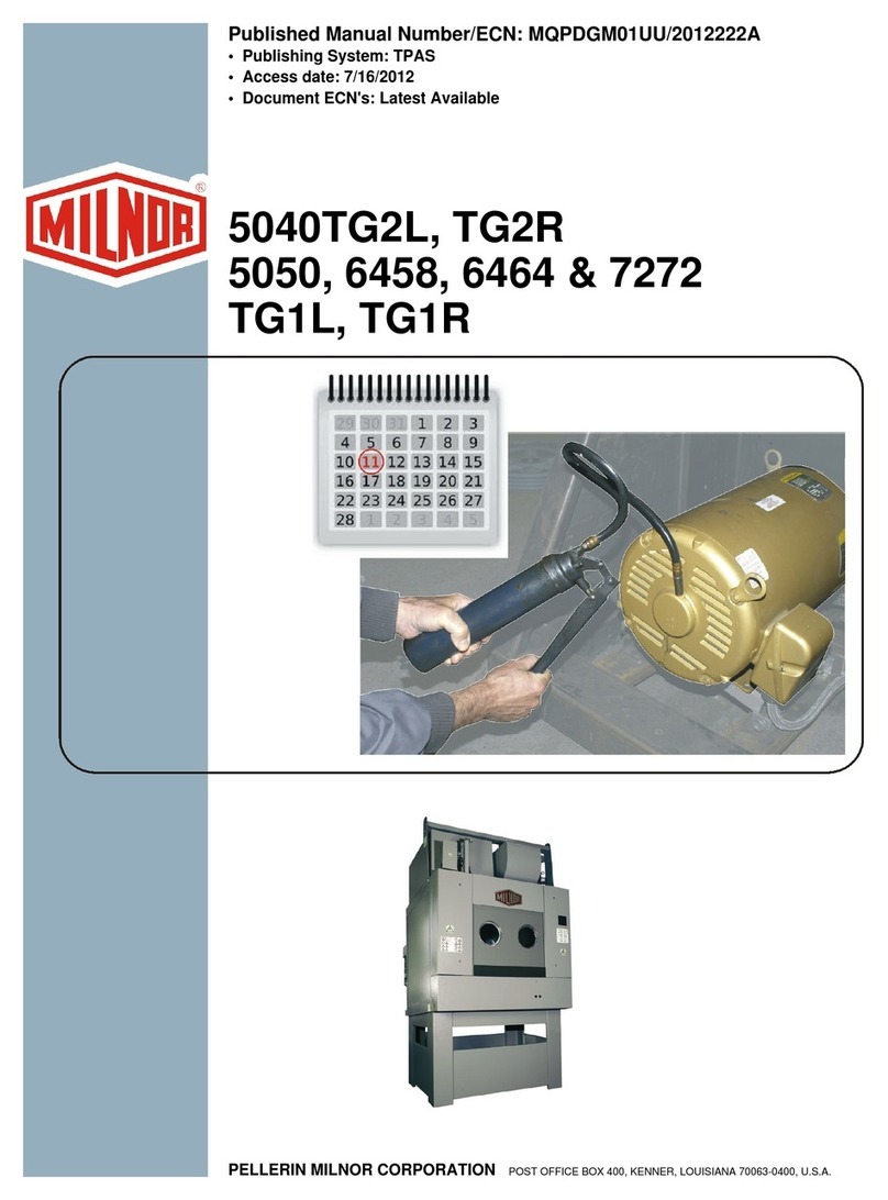
Milnor 50040 Use and care manual

Published Manual Number/ECN: MTDRYER1AE/87461N
• Publishing System: TPAS
• Access date: 12/29/1999
• Document ECN's: Latest Available
Technical Reference—
Dryer
PELLERIN MILNOR CORPORATION POST OFFICE BOX 400, KENNER, LOUISIANA 70063-0400, U.S.A.

Please Read
About the Manual Identifying Information on the Cover
The front cover displays pertinent identifying information for this manual. Most important, are
the published manual number (part number) /ECN (date code). Generally, when a replacement
manual is furnished, it will have the same published manual number, but the latest available
ECN. This provides the user with the latest information applicable to his machine. Similarly all
documents comprising the manual will be the latest available as of the date the manual was
printed, even though older ECN dates for those documents may be listed in the table of
contents.
When communicating with the Milnor factory regarding this manual, please also provide the
other identifying information shown on the cover, including the publishing system, access date,
and whether the document ECN’s are the latest available or exact.
References to Yellow Troubleshooting Pages
This manual may contain references to “yellow pages.” Although the pages containing
troubleshooting procedures are no longer printed on yellow paper, troubleshooting instructions, if
any, will be contained in the easily located “Troubleshooting” chapter or section. See the table of
contents.
Trademarks of Pellerin Milnor Corporation
The following, some of which may be used in this manual, are trademarks of Pellerin Milnor
Corporation:
Ampsaver®CBW®Gear Guardian®Milnet®Staph-Guard®
Autolint®Dye-Extractor®Hands-Off®Milnor®System 4®
Auto-Purge®Dyextractor®Hydro-Cushion®Miltrac System 7®
Autovac E-P Plus®Mildata®Miltron Totaltrol®
Comments and Suggestions
Help us to improve this manual by sending your comments to:
Pellerin Milnor Corporation
Attn: Technical Publications
P. O. Box 400
Kenner, LA 70063-0400
Fax: (504) 469-1849

Table of Contents
for MTDRYER1AE/87461N
Dryer
Page Description Document/ECN
1 Warranty BMP720097/92732A
2 How to Order Parts BMP720097R/72332A
3 How to Use Manual MTDRYER1AE MHDRYER1AE/87461N
4 Safety Precautions: The Milnor Dryer MSOPD451AE/86337N
7 Section 1: Installation
8 Service Connections for Gas, Steam & Hot Oil
Dryers, Conditioners & Shakers MSIND419AE/9740AV
10 How to Size Inlet and Discharge Air Ducting MSIN0105AE/9819AV
13 Section 2: Functional Description
14 The Hardware In Serial-Type Microprocessors MSFDA401DE/9020JV
19 How the "Normal Start - Hard Start - Normal
Run" Cylinder Drive Motor Starting System Works MSFD0103AE/87472V
23 Section 3: Operation
24 Description of Microcomputer Controls & Symbols
Used in the Instructions MSOPD428AE/87253N
26 Special Dryer Programming Features MSOPD446AE/86257N
31 Dry Cycle Programming MSOPD447AE/87437N
45 Programming Procedure for "Configure Dryer" (Program 7) MSOPD430AE/86186N
48 Special Procedures for Non-English Language Messages MSOPD429AE/86186N
51 Monitoring Automatic Operation of the Dryer MSOPD439AE/87016N
54 Manual Operation of the Dryer MSOPD438AE/86207N
59 Section 4: Service and Maintenance
60 Preventative Maintenance/Lubrication for Gas,
Steam and Hot Oil Dryers MSSMD426AE/87016
67 About the Steam Control System in Milnor Dryers MSSM0102AE/87396
71 How to Replace the Dryer T-Seal MSSM0108AE/8739BV
73 Section 5: Fuse and Wire Sizes
74 External Fuse and Wire Sizes for Dryers: 58040
CS1, CT1, SB1, TG2, TS1, TT1 BMP850052/95026V
75 External Fuse and Wire Sizes for Dryers: 58058
CS1, CT1, SB1, TG2, TS1, TT1 BMP850053/95026V
77 Section 6: Dimensional Drawings
79 Dimensions & Installation: 58040 TG1/TS1 BD40TG11AE/87201D
80 Options Affecting Dimensions: 58040 TG1/TS1 BD40TG11AB/87297D
81 Dimensions & Installation: 58058 TG1/TS1 BD58TG11BE/87201D
82 Options Affecting Dimensions: 58058 TG1 BD58TG11BB/87297D


3(//(5,10,/125&25325$7,21
/,0,7('67$1'$5':$55$17<
We warrant to the original purchaser that MILNOR machines including electronic
hardware/software (hereafter referred to as “equipment”), will be free from defects in material
and workmanship for a period of one year from the date of shipment from our factory with no
operating hour limitation. This warranty is contingent upon the equipment being installed,
operated and serviced as specified in the operating manual supplied with the equipment, and
operated under normal conditions by competent operators.
Providing we receive written notification of a warranted defect within 30 days of its discovery,
we will – at our option – repair or replace the defective part or parts, FOB our factory. We
retain the right to require inspection of the parts claimed defective in our factory prior to
repairing or replacing same. We will not be responsible, or in any way liable, for unauthorized
repairs or service to our equipment, and this warranty shall be void if the equipment is repaired
or altered in any way without MILNOR’s written consent.
Parts which require routine replacement due to normal wear – such as gaskets, contact points,
brake and clutch linings and similar parts – are not covered by this warranty, nor are parts
damaged by exposure to weather or to chemicals.
We reserve the right to make changes in the design and/or construction of our equipment
(including purchased components) without obligation to change any equipment previously
supplied.
ANY SALE OR FURNISHING OF ANY EQUIPMENT BY MILNOR IS MADE ONLY UPON
THE EXPRESS UNDERSTANDING THAT MILNOR MAKES NO EXPRESSED OR IMPLIED
WARRANTIES OF MERCHANTABILITY OR FITNESS FOR ANY PARTICULAR USE OR
PURPOSE. MILNOR WILL NOT BE RESPONSIBLE FOR ANY COSTS OR DAMAGES
ACTUALLY INCURRED OR REQUIRED AS A RESULT OF: THE FAILURE OF ANY OTHER
PERSON OR ENTITY TO PERFORM ITS RESPONSIBILITIES, FIRE OR OTHER HAZARD,
ACCIDENT, IMPROPER STORAGE, MISUSE, NEGLECT, POWER OR ENVIRONMENTAL
CONTROL MALFUNCTIONS, DAMAGE FROM LIQUIDS, OR ANY OTHER CAUSE BEYOND
THE NORMAL RANGE OF USE. REGARDLESS OF HOW CAUSED, IN NO EVENT SHALL
MILNOR BE LIABLE FOR SPECIAL, INDIRECT, PUNITIVE, LIQUIDATED, OR
CONSEQUENTIAL COSTS OR DAMAGES, OR ANY COSTS OR DAMAGES WHATSOEVER
WHICH EXCEED THE PRICE PAID TO MILNOR FOR THE EQUIPMENT IT SELLS OR
FURNISHES.
WE NEITHER ASSUME, NOR AUTHORIZE ANY EMPLOYEE OR OTHER PERSON TO
ASSUME FOR US, ANY OTHER RESPONSIBILITY AND/OR LIABILITY IN CONNECTION
WITH THE SALE OR FURNISHING OF OUR EQUIPMENT TO ANY BUYER.
BMP720097
92732A
1

How to order repair parts
Repair parts may be ordered either from the authorized dealer who sold you this
machine, or directly from the MILNOR factory. In most cases, your dealer will
have these parts in stock.
When ordering parts, please be sure to give us the following information:
1. Model and serial number of the machine for which the parts are required
2. Part number
3. Name of the part
4. Quantity needed
5. Method of shipment desired
6. In correspondence regarding motors or electrical controls, please include all
nameplate data, including wiring diagram number and the make or
manufacturer of the motor or controls.
All parts will be shipped C.O.D. transportation charges collect only.
Please read this manual
It is strongly recommended that you read the installation and operating manual
before attempting to install or operate your machine. We suggest that this manual
be kept in your business office so that it will not become lost.
PELLERIN MILNOR CORPORATION
32%2;.(11(5/$86$
FAX: Administration 504/468-9307, Engineering 504/469-1849, Service 504/469-9777
BMP720097R
72332A
2

3

4

5

6

Section 1
Installation
7

MSIND419AE/9740AV (1 of 2)
ÈSERVICE CONNECTIONS FOR GAS, STEAM, AND
HOT OIL DRYERS, CONDITIONERS, AND SHAKERS
ÊGeneral
The service connections which may be required depending upon machine model and optional features are as
follows:
1. Piped Inlets and Outlets: cold water, compressed air, gas, steam, hot oil, steam condensate or hot oil return
line or gas line vent, main air intake, main air exhaust. The sizes and locations of piped inlets and outlets are
shown on the dimensional drawing for your machine.
2. Electric Power Connections.
3. Electrical Control Connections.
ÊPrecautions for Piped Connections
1. Inlet pressure must be within the minimum/maximum range specified. Pressure outside of the specified range
may cause the machine to operate inefficiently or to malfunction and may damage machine components.
Do not distort valve bodies when connecting plumbing. Hold tension
against these valves with a wrench on the side of the valve onto which the
pipe is being connected; otherwise, the valve will be twisted and distorted.
2. When connecting water and steam inlets, always install unions and shut off valves at the point of connection
to permit removal of the machine components for servicing, if necessary.
ÏPiped Inlet Specifications
(See dimensional drawing for sizes and locations of connection points)
ÏSource Requirements
for Models
Description of Connection 50040 58040 58058 58080 72072 PipingSpecifications/Comments
Gasinlet(gasmodels)
Maximum BTU/HR (KCAL/HR)
at a water column of (mm)
Average BTU/HR (KCAL/HR)
at a water column of (mm)
950,000 (240,000)
13.5" (343)
500,000 (126,500)
13.5" (343)
1,400,000 (350,000)
13.5" (343)
1,000,000 (253,000)
13.5" (343)
1,800,000 (450,000)
13.5" (343)
1,400,000 (354,000)
13.5" (343)
2,700,000 (240,000)
18" (457)
2,000,000 (126,500)
18" (457)
Pipe material per plumbing code.
Steaminlet(steammodels)
Steam range (85 - 180 PSI)(6 - 12 ATU)
Steam range (160 - 225 PSI)(11 - 15 ATU)
Boiler horsepower (actual) for sizing boiler
600 LB/HR (272 KG/HR)
17 HP (12.75kW)
22 HP (16.5 kW)
600 LB/HR (272 KG/HR)
17 HP (12.75kW)
22 HP (16.5 kW)
950 LB/HR (431 KG/HR)
25 HP (18.75 kW)
30 HP (22.5 kW)
1300 LB/HR (591 KG/HR)
35 HP (26.25kW)
40 HP (30kW)
Pipe material per plumbing code. Steam consumption values assume dryer
loaded to rated capacity and ignores external energy losses in either the steam
delivery or condensate return piping. The horsepower “for sizing boiler”
provides for actual consumption and some external energy losses. See “ABOUT
THE STEAM AND HOT OIL CONTROL SYSTEMS...” (see Table of Con-
tents).
Hot Oil inlet (hot oil models)
Maximum pressure 50 PSI
Operating pressure 15 PSI
Recommended heat transfer media
MULTITHERM IG-2
Sized to provide
50 GPM (.19 m3/min)
745k BTU/HR
188,000 Kcal/hr at maximum
temperature of 500oF (260o C)
Sized to provide
75 GPM (.28 m3/min)
1,296k BTU/HR
327,000 Kcal/hr at maximum
temperature of 500oF (260oC)
Pipe material per plumbing code.
Main air intake
Maximum SCFM (CU M/MIN)
Maximum allowable back pressure
(water column) at maximum air flow (mm)
3,600 (102)
1/2" (13)
3,600 (102)
1/2" (13)
5,000 (142)
1/2" (13)
6,800 (193)
1/2" (13)
10,000 (283)
1/2" (13)
Ducting to exterior of building highly recommended, but may be left unpiped if
laundry always open to outside air. See “HOW TO SIZE DRYER INLET AND
DISCHARGE AIR DUCTING.”
Combustion air intake (gas only)
Maximum SCFM (CU M/MIN) 250 (7) 400 (11) 500 (14) 717 (20) No ducting required.
Sprinklerwaterinlet
(whensupplied) 35 PSI (2.4 ATU) minimum Piping material per plumbing code. 1 1/4" NPT minimum. Must be reliable,
non-interrupted source for fire safety.
Compressedairinlet (all models) Clean and dry 85 PSI (5.8 ATU) to 125 PSI (8.5 ATU) Piping material per plumbing code.
8

ANTIFREEZE protecting steam coil during shipping is drained at the
Milnor®factory. However, the steam condensate return line should be
routed to the sewer for the first hour of operation to prevent residual
antifreeze from entering the boiler system.
Ê
ÏPiped Outlet Specifications
(See dimensional drawing for sizes and locations of connection points)
Description
of Connection
Destination
Requirements or
Description Piping Specifications Comments
Gas line vent
(Gas models only) Must be vented to exterior
of building 1/4" stainless steel or
black iron Carries off any gas which
might escape gas valves.
Steam condensate outlet
(Steam models only) Return to boiler through
properly sized and
installed steam trap Per plumbing code See “ABOUT THE
STEAM AND
HOT OIL CONTROL
SYSTEMS . . .”
Vacuum breaker (steam) Vent tube to sewer
Hot oil outlet
(Hot oil models only) Return to boiler 58040 11/2" IPS Flange
58058 2" IPS Flange
Main air outlet Vent to exterior of building See “HOW TO SIZE DRYER INLET AND
DISCHARGE AIR DUCTING”
ÊPrecautions for Electrical Connections
SHOCK HAZARD—Electrical source can cause death or severe injury. Connec-
tions must be made by a competent electrician.
1. Prior to making power connections, read the instructions on all related tags.
2. “Stinger leg” if any, must only be connected to terminal L3, never to terminals L1 or L2.
3. See fuse and wire sizing information in schematic manual and on machine nameplate.
4. Verify all motor rotation. If the cylinder turns in the wrong direction, interchange the wires connected to L1
and L2. Never move L3.
ÊElectric Power Connections
The customer must furnish a remotely mounted disconnect switch with lag type fuses, circuit breakers, and
wiring between this box and the fuse box on the machine. The sizes of these fuses and wires, along with the motor
fuses supplied with your machine, depend on the machine voltage.
FIRE HAZARD—Do not operate this machine unless sprinkler is functional and
is connected to an adequate water source, as described in table of Piped Inlets.
Bumper guards
Height
determined
by user
Rear View
Install bumper guards (boxed separately) on
lower discharge end of dryer as shown.
ÎFIGURE 1 (MSIND419AE)
ÎBumper Guard Installation
SERVICE CONNECTIONS FOR GAS, STEAM, AND
HOT OIL DRYERS, CONDITIONERS, AND SHAKERS MSIND419AE/9740AV (2 of 2)
9

MSIN0105AE/9819AV (1 of 3)
ÈHOW TO SIZE INLET AND
DISCHARGE AIR DUCTING
ÊIntroduction
Proper airflow is a critical factor in maintaining optimum performance. The inlet and exhaust air ducts must
be correctly designed to prevent excessive pressure drop which will starve the machine of air, causing longer drying
cycles and possibly poor combustion in gas heated dryers.
It is highly recommended to always connect the air inlet to a source of outside air; other-
wise, the machine will be starved of air, unless large windows and doors ARE ALWAYS
OPEN—a climatic impossibility in most installations.
Provided the pressure drop is uniform throughout the entire drying cycle, your MILNOR machine will
provide a proper air flow against a maximum total pressure drop of .5" (13mm) water column. This value
must be measured between where the inlet and outlet air ducts connect to the machine and thus includes all suction
and discharge pressure drops caused by the inlet and outlet duct work, plus any external lint filter, roof-top wind
loads, etc.
Most external lint collectors with cloth filters have proven to be inadequate because fine
meshcloth filters tend to block rapidly duringa drying cycle, while coarse mesh clothfilters
tend to pass unacceptable quantities of lint.
Choose the correct duct size and routing to keep the total pressure drop below the recommended maximum
pressure. Note that round ducting is best because it minimizes pressure drop and tends to reduce lint build-up in the
duct. However, data for both round and rectangular ducts is given in a table in this section.
ÊPrecautions for Fabricating Ducting
1. The blower is adequately sized to overcome the pressure drop mentioned above, providing the pressure
drop is relatively constant. Moreover, different positions of the automatic airflow dampers in the dryer can
be selected to cope with different inherent but steady-state pressure drops in the duct. However, a variable
pressure drop (possibly caused by a lint filter that becomes progressively loaded or blocked during the
drying cycle) will significantly reduce productivity because of the following:
a. If the dampers are selected for a suitable airflow at the beginning of the drying cycle, when the lint filter is
newly stripped and relatively free, the airflow (and productivity) will be drastically reduced toward the
end of the drying cycle as the filter becomes loaded with lint.
b.If the dampers are selected for a suitable airflow at the end of the drying cycle, after the pressure drop has
increased because of the lint on the filter, the airflow at the beginning of the drying cycle will be so
great that the goods will tend to plaster themselves against the perforations inside the cylinder. This will
also effectively reduce the actual airflow through the goods and thus drastically reduce productivity.
2. Do not employ “turning vanes” in any external ducts connected to your machine. Turning vanes may
quickly clog with lint. Lint build-up in the ducts will reduce the airflow and the dryer’s performance, and
also cause a fire hazard!
3. Do not employ right angle elbows. Use only elbows with radii no smaller than that shown in FIGURE 1.
4. Adequately sized inspection covers should be placed near every elbow for the periodic removal of lint.
5. All transitions should be smooth. Transitions may be considered as straight duct if the taper is less than 7 1/2o.
6. Because the resultant varying pressure drop will prevent the machine from performing correctly, never con-
nect two or more machines to a common exhaust duct.
7. Two or more machines may be connected to a common powered wet or dry type lint collector, providing:
a. Separate ducts must be run from each machine to the collector, and,
b. The lint collector’s fan capacity must be capable of accommodating the maximum combined flow from all
machines connected to it. The lint collector must have a variable speed motor or other equivalent means
responsive to the number of dryers actually running to maintain a constant back pressure not greater
than .5" (13) water column, nor less than zero.
8. This information is intended to be general in nature and is provided only as a guide. MILNOR accepts no
responsibility nor liability resulting from the use of this information. You may find it advisable to employ
the services of a professional engineer licensed to practice in your area.
ÎFIGURE 1 (MSIN0105AE)
ÎValues Used in Table of Duct Sizes
10

ÊLaying Out Ducting (English Units)
Select ducting from the following table.
ÏData for Sizing Inlet and Exhaust Ducts for MILNOR Machines
Model D
(inches) FPM Losses in inches of water Rectangular Dimensions
Per
100
Feet
90˚ Elbows H
(inches) W
(inches) R
(inches)
Smooth Round 3 Pc. Round Rect.
Short Long Short Long
50040
58040
(3600
CFM)
18 2034 .31 .10 .07 .13 .11 .09 14 20 15.00
Dimensions of other equivalent rectangular elbows
15 19 14.25
16 17 12.75
17 16 12.00
19 15 11.25
20 14 10.50
58058
(5200
CFM)
20 2384 .37 .13 .09 .17 .14 .12 16 22 16.50
17 20 15.00
18 19 14.25
Dimensions of other equivalent rectangular elbows 19 19 14.25
19 18 13.50
20 17 12.75
22 16 12.00
58058
(5200
CFM)
22 1970 .22 .09 .06 .12 .10 .08 18 24 18.00
19 22 16.50
20 22 16.50
Dimensions of other equivalent rectangular elbows 22 20 15.00
22 19 14.25
24 18 13.50
58080 Consult MILNOR factory
72072
(10000
CFM)
30 2865 .15 .21 .17 .28 .24 .14 23 33 31.00
Dimensions of other equivalent rectangular elbows
24 31 30.00
25 30 28.75
26 28 28.00
27 27 27.25
28 26 26.75
30 25 24.50
31 24 23.75
33 23 22.75
To determine the back pressure of your duct work, complete the following formula:
Pressure Drop = Length of Straight Duct/100 x Loss Per 100’(from table)
+ Number of Short Elbows x Loss (from table)
+ Number of Long Elbows x Loss (from table)
+ Maximum Back Pressure from Lint Collector
Example (see illustration below):
Pressure Drop (P.D.)= .14 + .02 +.06 + .02 + .12 + .03 + .25 = .64 inches of water
ÎFIGURE 2 (MSIN0105AE)
ÎExample Duct Layout (English)
HOW TO SIZE INLET AND
DISCHARGE AIR DUCTING MSIN0105AE/9819AV (2 of 3)
11

ÊLaying Out Ducting (Metric Units)
Select ducting from the following table.
ÏData for Sizing Inlet and Exhaust Ducts for MILNOR Machines
Model D
(centi-
meters)
Meters
per
second
Losses (in millibars) Rectangular Dimensions
Per
100
Meters
90˚ Elbows H
(centi-
meters)
W
(centi-
meters)
R
(centi-
meters)
Smooth Round 3 Pc. Round Rect.
Short Long Short Long
50040
58040
1.7 M3/sec
45.7 10.3 2.526 0.25 0.17 0.32 0.27 0.22 35.6 50.8 38.1
38.1 48.3 36.2
40.6 43.2 32.4
Dimensions of other equivalent rectangular elbows 43.2 40.6 30.5
48.3 38.1 28.6
50.8 35.6 26.7
58058
2.5 M3/sec 50.8 12.1 3.018 0.32 0.22 0.42 0.35 0.30 40.6 55.9 41.9
43.2 50.8 38.1
45.7 48.3 36.8
Dimensions of other equivalent rectangular elbows 48.3 48.3 36.2
48.3 45.7 34.3
50.8 43.2 32.4
55.9 40.6 30.5
58058
2.5 M3/sec 55.9 10.0 1.804 0.22 0.15 0.30 0.25 0.20 45.7 61.0 45.0
48.3 55.9 41.9
50.8 55.9 41.9
Dimensions of other equivalent rectangular elbows 55.9 50.8 38.1
55.9 48.3 36.2
61.0 45.7 4.3
58080 Consult MILNOR factory
72072
4.7 M3/sec 76 10.3 1.255 0.21 0.17 0.28 0.24 0.14 59 84 79
Dimensions of other equivalent rectangular elbows
61 79 77
64 76 73
66 71 71
69 69 69
72 66 68
75 63.5 62
78 61 60
82 58 58
To determine the back pressure of your ducting, complete the following formula:
Pressure Drop = Length of Straight Duct (Meters)/100 x Loss Per 100 Meters (from table)
+ Number of Short Elbows x Loss (from table)
+ Number of Long Elbows x Loss (from table)
+ Maximum Back Pressure from Lint Collector (millibars)
Example (see illustration below):
Pressure Drop (P.D.)= .337 + .054 +.15 + .043 + .30 + .082 + .622 = 1.588 millibars
ÎFIGURE 3 (MSIN0105AE)
ÎExample Duct Layout (Metric)
HOW TO SIZE INLET AND
DISCHARGE AIR DUCTING MSIN0105AE/9819AV (3 of 3)
12

Section 2
Functional Description
13

14

15

16
This manual suits for next models
4
Table of contents
Other Milnor Dryer manuals