Minarik 200-0416 User manual

4Q Isolation Adder Card
for RGx00 Series Drives
14300 De La Tour Drive • South Beloit, IL 61080
Phone: (815) 624-2745 • Fax: (815) 624-6334
www.minarikdrives.com
200-0416
An American Control Electronics Brand
ALL DIMENSIONS IN INCHES [MILLIMETERS]
Dimensions
L1 L2
230V
L2
115V GND F1 F2 A2 A1
SW501
C504
TB501
C503
C505
TB502
IC502
IC501
C502
115 230 230 115
SW502
L1 L2
FU502FU501
FAST ACTING
FUSES ONLY
S3 S2 S1 S0 RB1 RB2 -15 +15 T1 T2
T505
SCR501
MIN SPD FWD TQ REV TQ IR COMP MAX SPD FWD ACC REV ACC DB TACH
0.19 [5]
8.90 [226]
8.40 [213]
3.50 [89]
4.78 [121]
INH
COMPOL REVTPINPUT 2INPUT1COM+15-15L2L1OUT 2OUT1
115 230
INPUT VOLTAGE SELECT
T501
SIGNAL
INPUT
ADJUST
SW501
R501
IC505
1-5mA
4-20mA
10-50mA
P502
P503
MAX
OUT
MIN
OUT
C501
C502
C503
C504
IC501
IC502
IC503
IC504 123
P501
SW502
C506 C505 C508 C507
3.07 [78]
1.85 [47]
0.92 [23]
Step 1: Remove the 2 SCR screws and the 2 hex nuts on the base RGx00 unit.
Step 2: Remove the 2 PC board screws to the le and right of the calibraon trim pots on the base
RGx00 unit.
Step 3: Fasten the braket to the chassis using the SCR screws. The bracket’s short standoffs replace
the two hex nuts removed in step 1. Screw in the 1.75 inch standoffs to the regenerave drive PC
board.
Step 4: Mount the PCM board above the bracket and 1.75 inch standoffs. Secure the PCM board with
four PC board screws; two unscrewed from the regenerave drive PC board in Step 2 and two included
in the PCM board hardware kit.
INHIBIT
SO501
SO502
T501
R501
C501
SCR502 SCR503 SCR504
T502
T503
SCR505 SCR506
R504 R505 R506
T504
SCR507 SCR508
C509
C508
C507
C506
C510
SW504SW503
ARMATURE FEEDBACK
90 180 ARM TACH
R502 R503
MIN SPD FWD TQ REV TQ IR COMP MAX SPD FWD ACC REV ACC DB TACH
P501 P502 P503 P504 P505 P506 P507 P508 P509
SCR SCREWS
HEX NUTS
UN
INHIBIT
SO501
SO502
T501
R501
C501
SCR502 SCR503
T502
T503
T504
C507
C506
C510
SW504SW503
ARMATURE FEEDBACK
90 180 ARM TACH
R502 R503
MIN SPD FWD TQ REV TQ IR COMP MAX SPD FWD ACC REV ACC DB TACH
P501 P502 P503 P504 P505 P506 P507 P508 P509
UN
508
509
PC BOARD SCREWS 1.75 INCH STANDOFFS
BRACKET
MIN SPD FWD TQ REV TQ IR COMP MAX SPD FWD ACC REV ACC DB TACH
PC BOARD SCREWS
PC BOARD SCREWS
COMPOL REVTPINPUT 2INPUT 1COM+15-15L2L1OUT 2OUT 1
115 230
INPUT VOLTAGE SELECT
T501
SIGNAL
INPUT
ADJUST
SW501
R501
IC505
1-5mA
4-20mA
10-50mA
P502
P503
MAX
OUT
MIN
OUT
C501
C502
C503
C504
IC501
IC502
IC503
IC504 123
P501
SW502
C506 C505 C508 C507
Installation
Safety Warnings
• DO NOT INSTALL, REMOVE, OR REWIRE THIS EQUIPMENT WITH POWER APPLIED. Have a
• qualified electrical technician install, adjust and service this equipment. Follow the Naonal
• Electrical Code and all other applicable electrical and safety codes, including the provisions of the
• Occupaonal Safety and Health Act (OSHA), when installing equipment.
• Circuit potenals are at 115 or 230 VAC above earth ground. Avoid direct contact with the printed
• circuit board or with circuit elements to prevent the risk of serious injury or fatality. Use a non-
• metallic screwdriver for adjusng the calibraon trim pots. Use approved personal protecon
• equipment and insulated tools if working on this drive with power applied.
• Reduce the chance of an electrical fire, shock, or explosion by using proper grounding techniques,
•over-current protecon, thermal protecon, and enclosure. Follow sound maintenance procedures.
• Minarik Drives strongly recommends the installaon of a master power switch in the line voltage
•input. The switch contacts should be rated for 250 VAC and 200% of motor nameplate current.
• Removing AC line power is the only acceptable method for emergency stopping. Do not use
• regenerave braking, decelerang to minimum speed, or coasng to a stop for emergency stopping.
• They may not stop a drive that is malfunconing. Removing AC line power is the only acceptable
• method for emergency stopping.
• Line starng and stopping (applying and removing AC line voltage) is recommended for infrequent
• starng and stopping of a drive only. Regenerave braking, decelerang to minimum speed, or
•coasng to a stop is recommended for frequent starts and stops. Frequent starng and stopping can
• produce high torque. This may cause damage to motors.
• Do not disconnect any of the motor leads from the drive unless power is removed or the drive is
• disabled. Opening any one lead while the drive is running may destroy the drive.
• Under no circumstances should power and logic level wires be bundled together.
• Be sure potenometer tabs do no make contact with the potenometer’s body. Grounding the
• input will cause damage to the drive.
READ ALL SAFETY WARNINGS BEFORE INSTALLING THIS EQUIPMENT
Specifications
......................................................115/230 VAC ± 10%, 50/60 Hz, single phase
...............................................................................-25 to 25 VDC
...............................................................................-250 to 250 VDC
.................................................................................1-5 mA, 4-20 mA, 10-50 mA
............................................................................................................>25K ohms
..................................................................................................1K ohms
..............................................................................................235 ohms
............................................................................................100 ohms
.......................................................................................................-10 to 10 VDC
.............................................................................................................................0.01%
Power Requirements
AC Line Voltage
Input Signal Ranges
Voltage Signal, Narrow Range
Voltage Signal, Wide Range
Current Signal
Input Impedance
Voltage Signal
Current Signal, 1-5 mA
Current Signal, 4-20 mA
Current Signal, 10-50 mA
Output
Voltage Range
Linearity

250-0270 rev 1
No part of this document may be reproduced or retransmied in any form without wrien permission
from American Control Electronics. The informaon and technical data in this document are
subject to change without noce. American Control Electronics makes no warranty of any kind
with respect to this material, including, but not limited to, the implied warranes of its
merchantability and fitness for a given purpose. American Control Electronics assumes no
responsibility for any errors that may appear in this document and makes no commitment to
update or to keep current the informaon in this document.
AC Line: Connect the 115 or 230 VAC line to terminals 3 (L1) and 4 (L2).
Output Signal: Connect terminal 1 (OUT 1) to terminal S0 on the base unit.
Connect terminal 2 (OUT 2) to terminal S2 on the base unit.
Input Signal: Connect the signal common (-) to terminal 7 (COM). If using an analog voltage range
greater than 25 VDC, connect the signal reference (+) to terminal 9 (INPUT 2). Otherwise, connect
the signal reference (+) to terminal 8 (INPUT 1).
Direcon Switch: Connect a SPST switch to terminals COM and POL REV. Close the switch to change
motor rotaon direcon. Open the switch to change the motor rotaon back to it’s inial direcon.
Terminals +15 and -15 are used to power potenometers or other devices as needed.
Terminal TP is used during the calibraon procedure.
Calibration
The following minimum and maximum values should be known.
INmin - Minimum analog input signal.
INmax - Maximum analog input signal.
OUTmin - Minimum analog output signal.
OUTmax - Maximum analog output signal.
INmin and INmax is the voltage applied across terminals 7(COM) and 8 (INPUT 1) or 9 (INPUT 2).
OUTmin and OUTmax is the voltage across terminals 1 (OUT 1) and 2 (OUT 2) that connect to the lower board.
Calibraon Procedure
1. Ensure that switch SW501 on the -PCM board is properly set.
2. Connect (but do not power) the analog input signal as follows.
- Connect the signal negave (-) to terminal 7 (COM).
- For a current signal or a 0 - ± 25 VDC voltage signal, connect the signal posive (+) to terminal 8 (INPUT 1).
- For a 0 - ± 250 VDC voltage signal, connect the signal posive (+) to terminal 9 (INPUT 2).
3. Calibrate the regenerave drive’s MIN SPD trim pot full CCW and the MAX SPD trim pot full CW.
4. Apply AC line voltage and the analog input signal.
5. Set the input signal to INmin.
6. Adjust the MIN OUT trim pot (P503) so that the output voltage is OUTmin.
7. Set the analog input signal to INmax.
8. Calculate the test point voltage, Vtp;
9. Adjust the SIGNAL INPUT ADJ trim pot (P501) so that the voltage between terminals 7 (COM) and 10 (TP) is Vtp.
10. Adjust the MAX OUT trim pot (P502) so that the voltage output signal is OUTmax.
11. Repeat steps 4, 5, 6, 7, 9, and 10 using the same values.
Vtp = where m =
INmax* m
2
OUTmax - OUTmin
INmax - INmin
Connections
COMPOL REVTPINPUT 2INPUT 1COM+15-15L2L1OUT 2OUT 1
115 230
INPUT VOLTAGE SELECT
T501
SIGNAL
INPUT
ADJUST
SW501
R501
IC505
1-5mA
4-20mA
10-50mA
P502
P503
MAX
OUT
MIN
OUT
C501
C502
C503
C504
IC501
IC502
IC503
IC504 123
P501
SW502
C506 C505 C508 C507
115/230
VAC Line
S0 on
base
unit
S2 on
base
unit
0 - ± 25 VDC
1 - 5 mA
4 - 20 mA
10 - 50 mA
0 - ± 250 VDC
Direction Switch /
Polarity Reversal Switch
Startup
Select Switch (SW501)
Set the signal select switch SW501 based on the input signal type to be used.
Select Switch (SW502)
Set voltage select switch SW502 to either 115 or 230 to match the AC line voltage.
- Verify that no foreign conducve material is present on the printed circuit board.
- Ensure that all dip switches are properly set.
1. Apply the minimum analog voltage.
2. Apply AC line voltage.
3. Enable the drive.
4. Slowly advance the analog input signal. The motor slowly accelerates as the analog input signal is
raised. Connue unl the desired speed is reached.
5. Remove AC line voltage from the drive to coast the motor to a stop.
SELECT SWITCHES
STARTUP
INPUT
SIGNAL
LEVEL
1 - 5 mA
4 - 20 mA
10 - 50 mA
VDC
Other Minarik Computer Hardware manuals
Popular Computer Hardware manuals by other brands
Asus
Asus AAEON BOXER-6406-ADN user manual
ABB
ABB COM600 3.4 user manual
Link electronics
Link electronics SDI to Analog Composite & Y/C DigiFlex 1159 Specification sheet
Panasonic
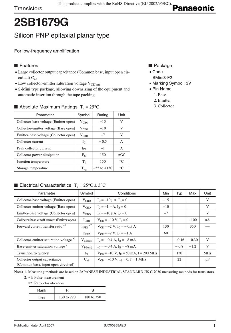
Panasonic 2SB1679G Specification sheet

ThermoKey
ThermoKey EPS Technical manual

INUX3D
INUX3D TerraPi Xtreme DUO Assembly instructions
