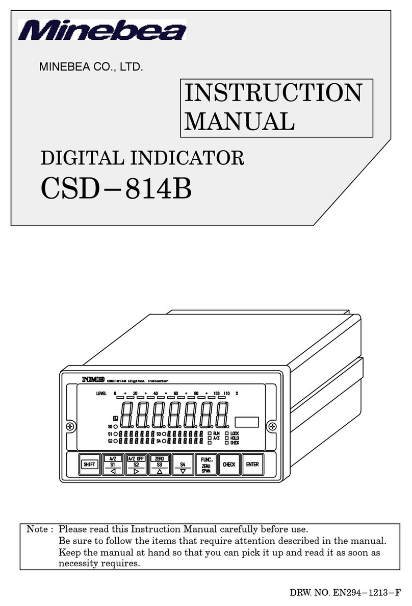
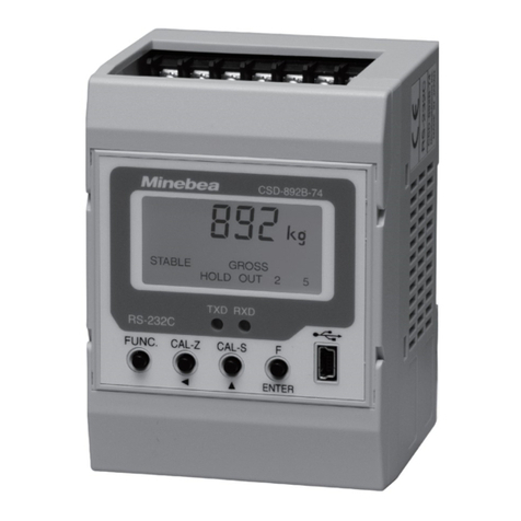
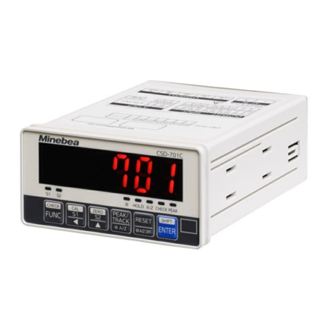
Minebea CSD-892B-73 User manual

General
Installation & Wiring
Change of mode
Calibration
Setting of Function
Setting of Comparator
Check Mode
Trouble Shooting
Specifications & Others
EN294-1961A
CC-Link interface
USB (RS-232C)
interface
WEIGHT CONVERSION MODULE
CSD-892B-73
Instruction Manual


I
FOREWORD
Thank you very much for your purchasing the Weight conversion module, model CSD-
892B-73. This instruction manual describes how to operate the devices as well as noteworthy
points. Note that handling or operating the device incorrectly may result in malfunctions.
Read this manual thoroughly before use for safety and optimal results.
Keep this instruction manual in a location where it in readily accessible to end users.
To read this manual, the basic knowledge of PLC program and CC-Link interface is needed.
Moreover, please refer to the manual of PLC and PLC program.
CC-Link is an abbreviation of 'Control & Communication Link'.
This product supports CSP+ (CC-Link Family System Profile Plus).
Please download the file for CSP+ from the following URL if required.
https://product.minebeamitsumi.com/product/category/mcd/i-amp/parts/
DigitalConversionmoduleCSD892series.html
In addition, please refer to HP of MITSUBISHI ELECTRIC for the details of CSP+.
Pictograms and conventions used in this manual.
This manual uses the following pictograms to indicate actions to avoid at all times, aspects
requiring caution, and other noteworthy matters.
Be sure to read the descriptions provided alongside these pictograms.
Warning This indicates circumstances in which incorrect handling may
result in death or serious injury to users. Avoid the actions
describes here at all times.
Caution This indicates circumstances in which incorrect handling may
result in injury to users or damage to property.
Point!
This indicates operating or procedural precautions or restrictions.
Always read the details included here to avoid malfunctioning.

II
For safe operation
Be sure to read this manual before
attempting to use the equipment.
Ⅰ.Location of installation
Caution
• Install in a location where temperature and humidity conditions are within the ranges described
below.
Environmental temperature-10 ~ 50 Preservation-20 ~ 60
Environmental humidity85 %RH or less. (Non-condensing)
Warning
• To minimize the risk of unforeseen accidents, avoid installing equipment in the following
locations.
Do not install in the following locations.
• Places exposed to direct sunlight and/or places in the high temperature.
• Places in a highly humid area.
• Places where the instrument is directly affected by vibrations or mechanical
shocks.
• Environments with full of dust or coarse particulates.
• Environments containing of corrosive gas or salt.
• Environments with raid change in temperature and/or humidity.
• Near the devices which generate magnetism or electromagnetic waves.
• Environments vulnerable to radioactivity or radioactivity rays.
• Environments where chemical reaction may take place such as a laboratory.
Please set up into the operation control panel when the instrument is used in
the following places.
• Places where drop of water splashes.
• Places where many dust and fine particles exist.

III
Ⅱ.Installing the instrument
When you set up two or more devices, you can install on the same panel with no
clearance in between.
Caution
• Please secure and set up the space between this instrument and the device
■Outline dimensions
Front Side
Unit : mm
72
6.296
67.4
■Direction of installation
When you install it in the control panel, please set it up in the front on upward so that
the front panel that includes the display of this instrument may come forward
Front installation
Vertical
installation
Upward installation
Installation on ceiling

IV
Ⅲ.Power supply
Warning
• Be sure to check that power supply is OFF when installing each cable. If an operator works
with power ON, operator may have an electric shock or the instrument may be destroyed.
• Before supplying power, check the indication of power voltage/specifications to be identical with
supplied power. If they are not identical, contact with us or our sales agent. Without checking
the above, operation may cause damage to the instrument or electric shock.
Caution
• Be sure to ground a grounding wire.
If a grounding wire is not grounded, it may cause malfunction of the instrument or an electric
shock to an operator.
Ⅳ.Instruction for usage
Caution
• Before using a new instrument, or when exchanging a strain gage applied transducer for a new
one, be sure to make calibration. If neglected, it may cause incorrect results in measurement
or malfunction in the instrument and moreover may cause damage to peripheral equipments.
When similar trouble occurs after calibration, be sure to make calibration again, even if
calibration has completed.
• When using the instrument, check that wires are connected properly. If neglected, correct
measurement cannot be obtained and it may cause malfunction in the instrument or cause
damage to peripheral devices or a critical accident.
• Improper change of setting during operation may cause incorrect measurement or malfunction,
or cause damage to peripheral equipments.
• Do not give the instrument such a shock as throwing something at it. It may cause damage or
destroy electrical circuits and even have loose resistance to environment or operability.
• Do not remove the cover of the case of the instrument, nor peel off the panel sheet nor take the
instrument into pieces. If neglected, it may cause damage to the case and the panel sheet and
even have the possibility of damage to resist to environments or operational performances.
Point!
• At the time of shipment from the factory, the instrument has been plated with a clear
sheet on the panel sheet for protective purpose. In case of application, use the
instrument after removing the clear sheet first.
• Do not push the panel sheet on the instrument with the excessive strong force nor
push it with sharp edge object such as a driver.
• If neglected, it may cause damage to the panel switch and even have the possibility
of damage to resist to environments or operational performances.


V
Ⅴ.Conformity standard
This instrument has suited the following standard.
EN61326-12013
"Electrical equipment for measurement, control, and laboratory use
EMC requirements"
"Immunity test requirements for equipment intended for use in
industrial locations"
JIS B 7611-22015
"Non-automatic weighing instruments - Metrological and technical
requirements and test - Part2: Measuring instruments used in transaction or
certification."
According to Annex C (Environmental Level H), (Environmental Level L).
RoHS compliant
Caution
• When the USB interface is used, the applied above standard is excluded.
• Please observe the following conditions strictly when this instrument suits the below. If
neglected, it may not conform to the above standard.
• Cable
Use the shielded cable other than the power cable.
• Shield processing
Please connect the shield cable of load cell with E terminal in upper terminal block.
Please connect the shield cable only for CC-Link interface with SLD terminal in the
connector for CC-Link interface.
Please make sure to do the shield prosessing on the cable only for CC-Link and
the external control I/O.
• Grounding
The ground shall apply the individual ground by using the F.G. terminal in lower
terminal block.
• Surge countermeasure parts
When applying to EN61326-1:2013, connect an external surge absorber (Model
RSP-DC24Q-4 Made by Okaya Electric Industries Co., Ltd.) or equivalent products
(breakdown voltage of 33V or more) in parallel to the terminal block (F.G., 24V,
0V). When applying to JIS B 7611-2:2015 level H, connect an external surge
absorber (ModelRSP-DC24Q-4 Made by Okaya Electric Industries Co., Ltd.) in
parallel to the terminal block (F.G., 24V, 0V) .When applying to JIS B 7611-2:2015
level L, no surge absorbers are required.

VI
Caution
• Please observe the following conditions strictly when this instrument suits the JIS standard.
If neglected, there is a possibility of not suiting the above-mentioned standard.
• Setting functions
As for the details of the function of the value of C Function and Function, please
refer the paragraph 5-2 and 7-2.
CF-03 [Condition of over display] shall be applied the value of 2.
CF-08 [Net weight sign inversion] shall be applied the value of 0.
CF-11 [Effective range of zero set] shall be applied with less than the value of 02.
CF-13 [Data width of zero tracking] shall be applied with less than 4% of weighing capacity.
F-01 [Setting of digital filter] shall be applied with more than the value of 016.
F-02 [Setting of analog filter] shall be applied with less than the set value of 040.
F-05 [Setting of stabilization filter] shall be applied with more than the value of 092.
F-06 [Data width of stabilization filter] shall be applied with less than the set value of 020.
F-07 [Time width of stabilization filter] shall be applied with more than the value of 05.
F-10 [Stability detection data width] shall be applied with the set value of more than 20.
F-11 [Stability detection time width] shall be applied with more than the value of 10.
F-15 [Net weight offset function] hall be applied the value of 00000.
Ⅵ.
Function set when this is used in the tank weighing system
Point!
• When using CSD-892B-73 as a tank weighing system, the setting of the function
shall be changed to as below.
This becomes the suitable setting for tank weighing system by easing the condition of
[Over display], [Zero set] and [Tare weight cancellation].
Examine this setting based on the user's weighing condition.
CF-03 Set the value of [Condition of overload display] to 1: (At exceeding 110 % of
Weighing capacity).
CF-10 Set the value of [Operating condition of ZERO set] to 1: (Operation by unconditional).
CF-11 Set the value of [Effective range of ZERO set] to 10: ( 10 % of weighing capacity).
CF-16 Set the value of [Operating condition of tare weight cancellation] to 3: (in normal by
Gross weight <= Weighing capacity ).

VII
Revision history
Date Instruction No. Reason of revised (Contents)
2022/04 DRW. NO. EN294-1961 First version ROM Ver.3.000
2022/05 DRW. NO. EN294-1961A
ECN No.FN22-0210
-Correction-
V.Conformity standard
<Before the change>
RoHS directive
<After the change>
RoHS compliant
2-4.Connecting of power supply and ground[Point!]
2-5.Connection with external control I/O
2-6.Connection of CC-Link interface[Point!]
<Before the change>
Please refer to [ . Applied standard] in [Safety
precaution] about the grounding to compliant with the
conforming JIS standard or EMC directive.
<After the change>
Please refer to [ .Conformity standard] in [For safe
operation] about the grounding to compliant with the
conforming JIS standard or EMC directive.

VIII
CONTENTS
FOREWORD I
For safe operation II
. Location of installation II
. Installing the instrument III
. Power supply IV
. Instruction for usage IV
. Conformity standard V
.
Function set when this is used in the tank weighing system VI
Revision history VII
1. Each Name and Function 1
1-1. Front panel 1
1-2. Upper and lower part of front panel 3
2. Installation and Wiring 4
2-1. Attaching to and Removing from a DIN rail 4
2-2. Note for connecting wires 4
2-3. Connection with strain gage based transducer 5
2-4. Connecting of power supply and ground 10
2-5. Connection with external control I/O 11
2-6. Connection of CC-Link interface 12
2-7. Connection of surge absober 13
3. Operation 14
3-1. Changeover of mode 14
3-2. Display transition diagram 16
4. Calibration mode 17
4-1. What is calibration? 17
4-2. Procedure of calibration 18
4-3. Selection of calibration method 20
4-4. Fine adjustment and re-calibration of calibration 20
4-5. Item set if necessary after a calibration 20
4-6. Details of calibration procedure 21
4-7. Fine adjustment of ZERO and SPAN 27
4-8. Digital linearization 29
4-9. Calibration only of ZERO 31
4-10. Simple calibration 32

IX
5. C function mode 36
5-1. Setting method of C function mode 36
5-2. Details of C function data 37
6. Various operations by C function data 39
6-1. Decimal point display position 39
6-2. A/D sampling 39
6-3. Condition of overload display (Display of [OL] and [-OL]) 39
6-4. Comparison operation display synchronization 39
6-5. Unit 39
6-6. Function to reverse the sign of net amount 40
6-7. ZERO set 40
6-8. ZERO tracking 40
6-9. Power on ZERO 42
6-10. Tare weight cancellation 42
6-11. Change of data stored place 43
6-12. Stability detection while setting 43
6-13. Gravity acceleration compensation 43
6-14. Calibration data (For reference) 45
6-15. Stability detection time width in calibration 45
6-16. Digital linearize clear 45
6-17. C function clear 45
7. Function mode 46
7-1. Setting method of function mode 46
7-2. Details of function data 47
8. Various operations by function data 51
8-1. Digital filter 51
8-2. Analog filter 51
8-3. Stabilization filter 51
8-4. Key lock function 53
8-5. Stability detection 53
8-6. Net amount offset function 54
8-7. Hold 54
8-8. Operation of F/ENTER 55
8-9. External control I/O 55
8-10. Maintenance date, Maintenance number 58
8-11. Lighting time of liquid crystal back light 58
8-12. Function clear 58
9. S function mode 59
9-1. Setting method of S function mode 59
9-2. Details of S function data 60

X
10.Various operations by S function data 62
10-1. Measurement mode 62
10-2. Control mode 62
10-3. Operation of comparative signal 62
10-4. Comparative operation at NEAR ZERO (ZERO BAND) 62
10-5. Comparative operation of FULL 62
10-6. Batch Monitoring Timer 62
10-7. Set for operation at the time of batch start 63
10-8. Full flow comparison interrupt timer 63
10-9. Medium flow comparison interrupt timer 63
10-10. Dribble flow comparison interrupt timer 63
10-11.Automatic free fall compensation 64
10-12.Judgement condition 64
10-13.Waiting time for judge 64
10-14. Set for operation of compensation flow 64
10-15. Set for operation of measuring finish output 65
10-16. Set for discharging operation after measuring finish 66
10-17.S function clear 66
11.Measurement mode 67
11-1. Selection method of Measurement mode 69
11-2. Simple comparison mode 70
11-3. 5 steps comparator mode 78
11-4. Sequential mode 84
12.Stored data of setting d
ata 91
12-1. Data stored in internal RAM 91
12-2. Data stored in EEPROM 91
12-3. Data that stored place can be changed 91
13.Check mode 92
13-1. Setting method of Check mode 92
13-2. EzCTS mode 93
13-3. Confirmation of ROM version 93
13-4. Confirmation of external control input 94
13-5. Confirmation of external control output 94
13-6. Confirmation of load cell output voltage (Monitor mode) 95
14.CC-Link interface 96
14-1. General 96
14-2. Features 96
14-3. Specifications of CC-Link interface 96
14-4. PLC memory explanation 98
14-5. Address map 99

XI
14-6. Calibration by CC-Link interface 125
14-7. Calibration for only zero point by CC-Link interface 133
15.Operation method 136
15-1. Writing set value 136
15-2. Writing/Reading by general command 136
15-3. Shift to condition that can be communicated 137
15-4. Error condition / Reset requesting flag 138
15-5. CPU normal operation signal 138
16. USB (RS-232C) interface 139
16-1. Specifications of interface 139
16-2. Operation mode 139
16-3. Command data format 141
16-4. Data format for stream mode 156
16-5. Data format of calibration by transmission 158
17.Trouble shooting 172
17-1. Basic chapter 172
17-2. External control I/O chapter 173
17-3. CC-Link interface chapter 173
17-4. USB interface chapter 173
17-5. EzCTS chapter 173
18. Specifications 174
18-1. Specifications for analog 174
18-2. Specifications for digital 174
18-3. Interface 175
18-4. General specifications 175
18-5. Specifications at the time of shipment 175
18-6. Accessories 175
19. Error display 176
20.Warranty 178
20-1. Warranty 178
20-2. Repair 178
20-3. Life time of using parts 178
21.Pattern of character 179
22.Function setting table 180


1
General
1. Each Name and Function
1-1. Front panel
Unit display section
Display the setting unit of weighing.
Load display section
Display the Gross/Net, Overload or Error.
In the various setting mode, display the condition and the setting value.
Condition display section
Display the condition of CSD-892B-73.
ZERO Light on when the zero calibration is processed.
SPAN Light on when the span calibration is processed.
mV/V Light on when mV/V value is displayed, like in the calibration by the
numeric input, or in monitoring the output value from load cell.
STABLE Light on when the weighing data is in stable condition.
TARE Light on when the tare weight cancellation is processed.
GROSS Light on when the display of weighing is set to the gross value.
NET Light on when the display of weighing is set to the net value.
CZ Light on when the displayed load value is zero, and within 1/4 of the
scale intervals.
LOCK Light on when the key lock is effective.
HOLD Light on when the holding is effective.
ERROR Light on when the error signal is output.
OUT1 ~ 5 The number lights on when the corresponding external output is turning on.
①Unit display
③Condition display
⑨USB interface
connector
⑧F/ENTER key
⑤
FUNC. key
⑦CAL-S/ ▲key
⑥
CAL-Z/ key
②
Load display
④
Status LED

2
General
Status LED
The sending / receiving status is monitored with two LED.
Name of LED Turn on Turn off Blinking
RUN Normal During reset
No communication
-
SD Transmitting - -
RD Receiving - -
ERROR Abnormal setting
CRC error occurs
Trouble
Normal When the set is
changed.
FUNC. key
Enter into the function mode, or change each status to the former status set in advance.
Shifts to Calibration setting mode by pushing for 2 seconds or more.
CAL-Z/ key
Carry up the setting value.
Shifts to ZERO calibration mode of a simple calibration by pushing for 2 seconds or
more. Also shifts to calibration lock mode of a simple calibration.
Also shifts to calibration lock mode of a simple calibration by pushing for 2 seconds or
more CAL-Z/ and CAL-S/ key at the same time.
CAL-S/key
Set value increment. Shifts to SPAN calibration mode of a simple calibration by pushing
for 2 seconds or more.
F/ENTER key
Resister the setting value, and execute function set in F/ENTER key.
(Selectable from None, Hold, ZERO set, ZERO clear, Tare weight cancellation, Tare
weight clear, Changeover of gross /net value, Shift to the setting mode of comparator,
Check the CC-Link station number.)
Default function has set to Check the CC-Link station number.
Connector for USB interface (mini-USB connector type-B)
USB interface is used for reading the set data from host and writing the parameter
details set for the measurement and calibrate.
The subject driver installation is needed.
Please download from our homepage, and install it to the PC.
Additionally, EzCTS_USB1 (Optional software for PC) is convenient for reading, writing,
savingand printing the setting data by connecting with PC.
Point!
• Please refer to [4-10. Simple calibration] for the details.

3
General
1-2. Upper and lower part of front panel
④CC-Link interface connector
③Terminals for load cell
(Upper part terminals)
①Cover-1 and -2 of terminal block
②Terminals for power supply and
external control I/O
(Lower part terminals)
Cover-1 and -2 of terminal block
This is the protection cover of upper / lower terminal blocks.
Please connect after opening the cover when you wire to the terminal block.
Terminals for power supply and external control I/O (Lower part terminals)
This terminal block is used for the connection with DC24V power supply, grounding and external
control equipment.
The external control I/O can use the input up to 3 points and the output up to 5 points at
maximum.
Terminals for load cell (Upper part terminals)
4 units of strain gage based transducer (350 ) can be connected in parallel.
CC-Link interface connector
This connects to PLC with CC-Link connector of accessory.

4
Installation & Wiring
2. Installation and Wiring
2-1. Attaching to and Removing from a DIN rail
This instrument adopts the rail mounting type with 35 mm width of DIN standard.
The procedures of attaching and removing are as follows:
Attaching method to a DIN rail
Hang an upper claw of this instrument on the
upper side of DIN rail.
Press this instrument onto DIN rail until a click
sound is heard.
Confirm the firm fixation.
Removing method from a DIN rail
Confirm all the cables including the power
supply cable have come off from the main
body.
Pull a lower claw of this instrument downward
from the front direction using a screwdriver,
and then remove this instrument from the DIN
rail.
2-2. Note for connecting wires
When connecting wires, turn off the power supply without fail.
Do not supply the electric power until the installation is completed. There is no switch
that switches ON/OFF of power supply in the main body.
Do not drop or do not give the high impact because the terminal block is made by the
resin.
Please separate the cable connected with the main body from the noise source such as I/
O for the control, power supply line as much as possible.
Be sure to connect a grounding wire with exclusive use of D-type single grounding. Do not
share it with other groundings for power supply system.
The tightening torque of terminal screws on the terminal board is 0.6 Nm.
Please use the solderless terminal with 6.2 mm or less in the width.
(O-type 1.25-3 or Y-type 1.25-3)

5
Installation & Wiring
2-3. Connection with strain gage based transducer
This instrument can connect with the strain gage based transducers, such as load cells,
pressure sensors, etc. Please connect the load cell to the upper terminal block. We describe
here as an example of connection with load cells, and please process it similarly for
connecting with other strain gage based transducers.
🅐+ EXC Load cell power supply + Red
🅕+ SEN Sensing input + Orange
🅖- SEN Sensing input - Black
🅒- EXC Load cell power supply - White
🅓+ SIG Load cell input + Green
🅑- SIG Load cell input - Blue
🅔SHIELD Shield Yellow
Point!
• When tension is applied with the use of tension type or universal (tension/com-
pression) type load cell, and display of (+) direction is required, connect input (+) of
load cell to terminal B and input (-) of load cell to terminal D individually.
(Excluding our load cell, CLS-A, CL- B, UL(A) and UT(A)).
• Cable color is our standard.
(Excluding our load cell, LSM-B series.)
Case 6-wires type connection cable
Load cell power supply + (Red)
Sensing input + (Orange)
Sensing input - (Black)
Load cell power supply - (White)
Load cell input + (Green)
Load cell input - (Blue)
Shield (Yellow)
+SIG
-SIG
+EXC
-EXC
Load cell
Point!
• When the length of CAB-501 (our standard cable) is more than 100 m totally, the
accuracy may be out of warranty as the remote sensing function of the instrument
does not work enough due to the resistance of the cable.
• Shorten the remote sensing input + and remote sensing input - near the main body
of load cell. When the short is made near the instrument, the sensing function does
not work as it is.

6
Installation & Wiring
Case 4-wires type connection cable
Load cell power supply + (Red)
Load cell power supply - (White)
Load cell input + (Green)
Load cell input - (Blue)
Shield (Yellow)
+SIG
-SIG
+EXC
-EXC
Load cell
Short-bar attached.
Point!
• When you use the 4-wires cable, shorten the load cell terminals A - F with the
attached short-bar. CSD-892B-73 does not work in normal operation when the
terminal F and G is in the open status.
• When the length of CAB-502 (our standard cable) is more than 30 m totally, there
may have the case that the accuracy is out of warranty due to the resistance of
cable, the input voltage of the instrument will be decreased.
• When you use a zener barrier, connect by using above method with 4-wires cable.
Table of contents
Other Minebea Measuring Instrument manuals

Minebea
Minebea CSD-801 User manual

Minebea
Minebea CSD-581-74 User manual

Minebea
Minebea CSD-892B-07-25 User manual

Minebea
Minebea CSD-892B-74 User manual

Minebea
Minebea CSD-903-73 User manual

Minebea
Minebea CSD-701C User manual

Minebea
Minebea CSD-401 User manual

Minebea
Minebea CSD-814B User manual

Minebea
Minebea MIS-202-PT User manual

Minebea
Minebea CSD-891B User manual
Popular Measuring Instrument manuals by other brands

Liverage
Liverage Fiber Checker User manual and specifications

Billion
Billion SG3010 Series user manual

PCE Instruments
PCE Instruments PCE-CT 28 manual

Haltech
Haltech HAL-HCO106 Operational manual

Agilent Technologies
Agilent Technologies PN 8510-16 Product note

FLIR
FLIR identiFINDER R200 quick start guide