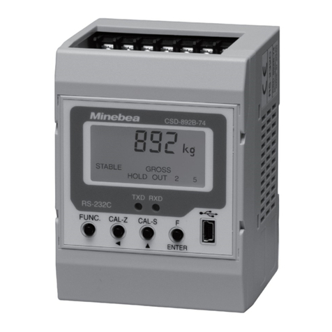
Minebea CSD-581-74 User manual

DIGITAL INDICATOR
CSD-581-74
Instruction Manual
EN294-1108-J

.

I
FOREWORD
Thank you very much for your purchasing our Digital Indicator CSD−581−74.
This manual explains installation procedures and connecting method and also operating
method for Digital Indicator CSD−581−74. Make use of it properly after reading through
the manual carefully.
Be sure to deliver the manual to the end user. Moreover, the end user should keep the
manual at hand after reading it over.

II
Marks and arrangement used in this manual
The following marks are attached to the explanation on the matters that indicate
“Don’t do this.”, “Take care.” and “For reference”.
Be sure to read these items where these marks are attached.
Warning ●Precautions which must be followed to prevent the possibility of
accident or serious injury to the operators.
To avoid possible hazard, don’t perform any procedure described here.
●Precautions and important informations for safe operation and
service personnels. Be sure to read to prevent from malfunction.
Mark during operation
●Press the switch.

III
For safe operation
Be sure to read this manual before use.
1. Installation place
●Use the instrument where the temperature/humidity specifies within
the range as follows:
Environmental temperature : −10 ℃to 50 ℃
Environmental humidity : Less than 85 %R.H.(Non condensing.)
(1) Location where installation is not allowed.
Warning ●Don’t locate the instrument on the places such as follows:
It may cause an unexpected faulty in the instrument.
DDon’t expose the instrument in direct sunlight and/or high temperature
area.
DDon’t use the instrument in a high humid area.
DDon’t install the instrument where there is high mechanical vibration.
DDon’t use the instrument where there are excess of dusts and fine
particles.
DDon’t install the instrument where there includes any corrosive gas or any
salty atmosphare.
DDon’t install the instrument where there is rapid change of temperature
and humidity.
DDon’t install the instrument near the devices that are magnetized or
generate an electromagnetic field.
DDon’t install the instrument where there may suffer radioactivity or
radioactive rays.
DAvoid the location where chemical reaction may take place such as in a
laboratory.

IV
(2) Installation
Warning ●There are a lot of electrical parts installed on the P.C. board of the
instrument, so there have fears to occur electrostatics destruction.
Because of this, operator should discharge electricity from him/her by
touching some metal sections other than the instrument before use.
Besides, take care not to touch electrical parts when you operate.
●When installing the instrument, install as referring to the following
dimensions and secure the space around the instrument.
●When installing the instrument, we recommend you to prepare for
the cover considering the following items.
Besides, we prepares installation to cover for this instrument as
an option.
1 There are a lot of ICs on the P.C. board of the instrument that may
be destroyed eternally due to static electricity, so in order to
prevent the human from touching them directly.
2The battery is installed on the P.C. board of the instrument, so in
order to prevent from shorting between the polarities of battery
carelessly.
3There are some places that have high temperature around 50 ℃or
more in the room temperature, so in order to prevent the operator
from touching the areas carelessly.
●The protection tape for the battery polarities is applied on the part of
battery(front side) and battery terminal(rear side) of this instrument.
When you use the instrument, peel them off.
●The bag for packaging this instrument is made from the conductive
material, so don’t use this bag with the protection tape for each
battery polarities removed.

V
Each dimensions of the instrument and required dimensions for the environmental
spaces are as follows:
Dimensions for installation
220
113
497 115
122
130
4
6−φ4 land□6
9
1.6
25
(7)
4
4
Secured space for application
Unit:mm
Secured space for application
Dimensions when the optional metal cover(CSD581−P80) is installed.
250
240
5(5) 4−φ6
(195) (31) (24)
(2) 140
100 20
(20)
1
(37.6)
Unit:mm
SW207 SW208 CN202

VI
2. Power supply
Warning ●Be sure to check that power supply is off when installing each cable.
If the work is done with the power fed, there may have the possibility
of electric shock to the operator or even the possibility of destroying
the instrument.
●Before supplying the power, check that the indication of power supply
voltage/specifications for the instrument and the power going to
supply should be the same. If they are not equal, contact us.
If you use the instrument without checking them, it may
cause a damage in the instrument or electric shock to the operator.
●Grounding wire should be grounded securely. When grounding wire is
not connected, it may cause a malfunction of the instrument or
electric shock to the operator.
3. Application note
Warning ●Before using a new instrument or exchanging the strain gage applied
transducer for a new one, be sure to make calibration.
If calibration shall not be made, correct measured results may not be
obtained nor it may cause a malfunction in the instrument and there
may exist damage in peripheral equipments.
Besides, even though calibration has been made, there may occur the
similar case when the result is not correct, so make calibration again.
Warning ●In case of using the instrument, check that the connections are
executed properly. If not connected properly, correct measured result
will not be obtained, nor it may cause malfunctions of the instrument,
damage to the peripheral equipments or even worse serious accidents.
Warning ●When change of setting is made carelessly on the instrument during
measurement, it may cause malfunction in the instrument and also
possibility of damage in peripheral equipments.

VII
Warning ●Do not shock the instrument such as throwing something on it.
If neglected, it may cause destruction of the parts and damage to the
electrical circuits.
Warning ●Don’t push the key switch section on the instrument with
unnecessary strong force nor push it with sharp−edge object such as
driver. If neglected, it may cause a damage to the key switch and even
have the possibility of damage to operational performance.
Warning ●Don’t remove the parts of the instrument, nor take the instrument
into pieces. If neglected, it may cause a damage to the parts and even
have the possibility of damage to the electric circuits.
Warning ●There are a lot of electrical parts installed on the P.C. board of the
instrument, but take care not to touch them. If neglected, there may
cause electrostatics destruction.
Warning ●The P.C. board of the instrument have some sections that have high
temperatures around 50 ℃or more in room temperature for a while
during supplying power or shutting off power supply (”MOD301”,
“U301”, “TR1, TR3 and radiator” indicated on the figure in the next
page.) , so care should be taken not to touch them. If neglected, it may
cause unexpected burns on your skin.
Warning ●The battery is installed on the P.C. board of the instrument, so care
should be taken not to short between the polarities of batteries
unnecessary. If neglected, there may cause remarkable deterioration
of the battery life, damage in the instrument or electric shock to the
operator.

VIII
Battery
U301
MOD301
Warning ●Don’t supply the power when the instrument is placed directly on the
conductive material such as metal, and also when it is covered in
conductive bag for packaging. If neglected, it may cause the damage
in the instrument or electric shock to the operator.
SW207 SW208 CN202

IX
History of revision
Date Instruction manual No. Details of revised point
OCT, 1999 DRW. NO.EN294−1108 First version
MAY, 2000 DRW. NO.EN294−1108-A
Due to ECN No. FN00−02060.
−Correction−
The sizes in the Outline dimensions in P. No.Ⅴ, 6 and 121
are changed.
JUL, 2001 DRW. NO.EN294−1108-B
Due to ECN No.FN01−02105.
-Change-
Change the unit of power consumption from “VA” to “W”.
-Correction-
7−2−5.(2)③“Reading out the load data”
→“Change of condition”
SEP. 2001 DRW. NO.EN294−1108-C
Due to ECN No.FN01−02134
-Changeー
Operating temperature range
“0 ℃to 50 ℃”→ “-10 ℃to 50 ℃”
Dec. 2003 DRW. NO.EN294−1108-D
Due to ECN No.FN03−02188
-Changeー
12−2. Screw size for attachment/removal of metal cover
“6−bind machine screw M3x6”→“6−bind machine screw
M3x10”
Sep. 2004 DRW.No.EN294-1108-E
Due to ECN No.FN04−02111
-Changeー
7−13. “Back−up life will be about 10 years or more...” has
changed to “Back−up life will be about 10 years.”
Apr. 2005 DRW.No.EN294-1108-F
Due to ECN No.FN05−02035
−Addition −
At the warning column in the wiring section, the clause of “
As there is a case which standard wiring color is different,
please confirm the inspection data sheet of the load cell
being used.” is added.
Feb. 2010 DRW.No.EN294-1108-G
Due to ECN No.FN10−02026
−Change −
Front cover’s logo is changed.
Oct.2010 DRW.No.EN294-1108-H
Due to ECN No.FN10−02140
−Change −
MInebea logo is changed.
Mar.2011 DRW.No.EN294-1108-I
Due to ECN No.FN11−02018A
−Change −
4−2.and 7−2−4. “DE−9S−N(made by JAE)”
→”DE−9S−NR by JAE or equivalent.”
Jan.2018 DRW.NO.EN294-1108-J Due to ECN FN17-02017
・Delete the company name in the contents.

X
Date Instruction manual No. Details of revised point
Jan.2018 DRW.NO.EN294-1108-J
Due to ECN FN17-02017
・Delete the company name in the contents.
Due to ECN FN15-02132B
-Correct miswriting-
1. Installation place
・Dimensions for installation
・Dimensions when the optional metal cover(CSD581−P80)
is installed.
3. Application note
2. Each name and function
3-3. Installation
・Dimensions for installation
・Dimensions when the optional metal cover(CSD581−P80)
is installed.
4-3-1.①Connection with one set of Load cell and CSD−581−74
4-3-1.②i) In case of application of CAB−502 (4 cores cable)
ii) In case of application of CAB−501(6 cores cable)
4-3-1.③i) In case of application of CAB−502(4 cores cable)
ii) In case of application of CAB−501(6 cores cable)
4-3-1.④i) In case of application of CAB−502 (4 cores cable)
ii) In case of application of CAB−501(6 cores cable)
4−3−2. Connection with external control input
4−3−3. Connection with open collector output
4−3−4. Connection with power supply and ground
7−7. Change of bridge power supply voltage
10−12. Outline dimensions
12−1. Replacement of fuse
12−2. Installation/uninstallation procedure of metal cover
CSD581−P80(Option)
-Additional-
2. Each name and function

CONTENTS
FORWARD 1.......................................................
Marks and arrangement used in this manual 2.......................
For safe operation 3...............................................
1. Installation place 3.........................................................
2. Power supply 6............................................................
3. Application note 6.........................................................
Record of revision 9.............................................................
1. General 1.................................................................
1−1. Features 1............................................................
2. Each name and function 2.................................................
3. Installation procedures 4..................................................
3−1. Installation place 4....................................................
3−2. Location where installation is not allowed. 4.............................
3−3. Installation 5.........................................................
4. Connecting method 7......................................................
4−1. Layout of terminals and RS−232C interface connector 7...................
4−2. Note on connection 8..................................................
4−3. Connections 9.........................................................
4−3−1. Connection with strain gage applied transducers 9..................
4−3−2. Connection with external control input 18...........................
4−3−3. Connection with open collector output 19............................
4−3−4. Connection with power supply and ground 20........................
5. Calibration procedures 21...................................................
5−1. Preparations 21........................................................
5−2. Calibration procedures 21...............................................
5−2−1. Calibration method to register the output of strain gage applied transducer
at the time of maximum display after setting the loa 22...............
5−2−2. Calibration method to register the output of strain gage applied transducer
at the time of zero and the maximum display 31.....................
5−2−3. Calibration method to register by reading output value of strain gage applied
transducer in the conditions of zero/actual load application individually 40
5−2−4. Fine adjustment on zero 51........................................
5−2−5. Fine adjustment on Span. 56.......................................
5−2−6. Calibration procedure to apply registration again for zero point only 61
5−3. Selection of calibration methods on each condition 66......................
5−3−1. In case of executing the calibration on the instrument newly. 66.......
5−3−2. When the calibration is executed again. 70...........................
6. Operation procedure 71.....................................................
6−1. “A/ZA” key 71..........................................................
6−1−1. Operations in Measurement mode 71...............................
6−1−2. Operations in another modes 71....................................
6−2. “A/Z OFF Y” key 71....................................................
6−2−1. Operation in Measurement mode 71................................
6−2−2. Operation is made in another mode 72..............................

6−3. “ZERO” key 72.........................................................
6−3−1. Operation in the Measurement mode 72.............................
6−3−2. Operation is made in another mode 72..............................
6−4. “FUNC.” key 72........................................................
6−4−1. Operation in the Measurement mode 72.............................
6−4−2. Operation in another modes 72.....................................
6−5. “CHECK” key 72.......................................................
6−5−1. Operation in the Measurement mode 72.............................
6−6. “ENTER” key 72.......................................................
7. Function and operation 73..................................................
7−1. External control input signal and open collector output signal 73............
7−1−1. Input signal for external control 73.................................
7−1−2. Open collector output signal 74.....................................
7−1−3. Equivalent circuit 74..............................................
7−2. RS−232C Interface 75..................................................
7−2−1. Related function 75...............................................
7−2−2. Specifications on interface 76......................................
7−2−3. Procedure of data transmission 76..................................
7−2−4. Pin layout and wiring of Connector 77..............................
7−2−5. Data format 78...................................................
7−3. How to use filter 84.....................................................
7−3−1. Digital filter 84...................................................
7−4. Zero tracking 85........................................................
7−4−1. What is zero tracking? 85..........................................
7−4−2. Set for zero tracking 85............................................
7−4−3. Target of zero tracking 86..........................................
7−4−4. Cancellation for compensation data by Zero tracking 86...............
7−5. Stabilized filter 87......................................................
7−5−1. What is stabilized filter 87.........................................
7−5−2. Setting for stabilized filter 87......................................
7−6. Various kind of functions for display 89...................................
7−6−1. Selection of display target on load indication 89......................
7−6−2. Selection of HOLD target 89.......................................
7−6−3. Range of load display 89...........................................
7−7. Change of bridge power supply voltage 90.................................
7−8. Tare weight cancellation(A/Z) 91.........................................
7−9. Zero set 91.............................................................
7−10. Digital tare weight cancellation 91.......................................
7−11. Key lock 92............................................................
7−12. CHECK value 92.......................................................
7−13. Memory position for setting data and so on 93.............................
7−14. Check mode 93.........................................................
7−14−1. Operating procedure for the check mode 94..........................
7−15. Monitor mode 98.......................................................
8. Function mode 100..........................................................
8−1. Setting method for function mode 100.....................................
8−2. List of Function 102.....................................................
8−3. Output target during stream mode of RS−232C interface 106................

9. Trouble shooting 107........................................................
9−1. Execute trouble shooting 108.............................................
9−2. Error display 117........................................................
10. Specifications 118...........................................................
10−1. Specifications for analog 118..............................................
10−2. Specifications for digital 118..............................................
10−3. Key switch function 118..................................................
10−4. External control function 118.............................................
10−5. Open collector output signal 119..........................................
10−6. RS−232C interface 119..................................................
10−7. Various kinds of function 119.............................................
10−8. General specification 119.................................................
10−9. Standard specifications at the shipment 119................................
10−10. Accessories 120..........................................................
10−11. Options 120.............................................................
10−11−1. Metal cover 120....................................................
10−12. Outline dimensions 121..................................................
11. Warranty 122................................................................
11−1. Warranty 122...........................................................
11−2. Repair 122..............................................................
12. Appendix 123...............................................................
12−1. Replacement of fuse 123..................................................
12−2. Installation/uninstallation procedure of metal cover CSD581−P80(Option) 124
12−3. Character’s pattern for display 125........................................

.

1
1. General
The instrument is a digital indicator for the application of strain gage applied transducers.
1−1. Features
Main features for CSD−581−74 are as follows :
(1) P.C. board type
Only one piece of P.C. board can perform the function of digital indicator with RS−232C
Interface, and it is suitable for the application inside of control panel.
(2) Automatic calibration function
By the registration for rated output data (X.XXXX mV/V) of strain gage applied transducer,
calibration of the instrument can be performed automatically.
(3) Calibration with RS−232C
Calibration can be performed by the communication through RS−232C.

2
2. Each name and function
①④⑤⑥⑦⑧⑨③
②⑩
⑬
⑮
⑫
⑪⑭
1Load display
The load data is shown in Measurement mode, and status display is shown in various kinds of
Calibration mode and Setting mode.
2POL. (Polarity) display
Displays polarities for load data. Lights on when the load data is minus “−”.
3Status display
RUN Lights on when the instrument is in the Measurement mode.
A/Z Lights on when Tare weight cancellation is performed(A/Z ON).
And puts off when Tare weight cancellation is cleared. (A/Z OFF)
LOCK Lights on when the connection between the LOCK and COM. of the external control
input are shorted. Key switch operation is unavailable during lighting on.
HOLD Lights on when the connection between the HOLD and COM. at external control
input is shorted.
CHECK Lights on when CHECK is ON with the “CHECK” key pressed.
4“A/Z A” key
Executes Tare weight cancellation (A/Z).
Moreover, it will apply to carry up the digit of various kinds of setting values.
5“A/Z OFF Y”key
Executes Tare weight cancellation clear(A/Z OFF). Moreover, it is applied for numerical
increment at the time of various kinds of setting.
6“ZERO” key
Executes Zero set (One touched zero adjustment).
7“FUNC.” key
Used for shifting to the Function mode.
SW207 SW208 CN202
⑯

3
8“CHECK” key
Used when ON/OFF operation of CHECK value is required.
9“ENTER” key
Used for registering the set value at the time of various kinds of settings.
10 Position of pasting the Unit seal
As necessity requires, paste the Unit seal attached.
11 Terminals No. 1
Connects with various kinds of strain gage applied transducer such as load cell, grounding
wire and DC power supply.
12 Terminal No. 2
Connects with “RUN”, “ERROR” for open collector output, and external control input.
13 RS−232C interface connector
Connects with RS−232C interface.
14 Bridge power supply voltage changeover switch
Used when the bridge power voltage is selected from “10 V” and “2.5 V”.
15 Monitoring LED for RXD or TXD
LED used for monitoring RXD or TXD of RS−232C interface.
⑯ DIP switch for operation change when program is written
Use it at the time of the program rewriting.
Do not change the setting. When the setting is changed, it doesn't operate.
Only SW208-1 is turned on when the customer is used, and the other seven poles are turning off.

4
3. Installation procedures
3−1. Installation place
●Use the instrument where the temperature/humidity specifies within
the range as follows:
Environmental temperature :−10 ℃to 50 ℃
Environmental humidity :Less than 85 %R.H.(Non condensing.)
3−2. Location where installation is not allowed.
Warning ●Don’t locate the instrument on the places such as follows:
It may cause an unexpected faulty in the instrument.
DDon’t expose the instrument in direct sunlight and/or high temperature area.
DDon’t use the instrument in a high humid area.
DDon’t install the instrument where there is high mechanical vibration.
DDon’t use the instrument where there are excess of dusts and fine particles.
DDon’t install the instrument where there include any corrosive gas or any salty
atmosphere.
DDon’t install the instrument where there is rapid change of temperature and humidity.
DDon’t install the instrument near the devices that are magnetized or generate an
electromagnetic field.
DDon’t install the instrument where there may suffer radioactivity or radioactive rays.
DAvoid the location where chemical reaction may take place such as in a laboratory.
Table of contents
Other Minebea Measuring Instrument manuals
Minebea
Minebea CSD-892B-74 User manual

Minebea
Minebea CSD-904-EX User manual

Minebea
Minebea CSD-891B User manual

Minebea
Minebea CSD-892B-07-25 User manual

Minebea
Minebea CSD-709 User manual

Minebea
Minebea CSD-801 User manual

Minebea
Minebea MIS-202-PT User manual

Minebea
Minebea CSD-814B User manual

Minebea
Minebea CSD-903-73 User manual

Minebea
Minebea CSD-892B-73 User manual